 Download PDF· Rev 2.0.1
PCE Integration Guide
LiFe² 5120S
Inverter and Charger Settings
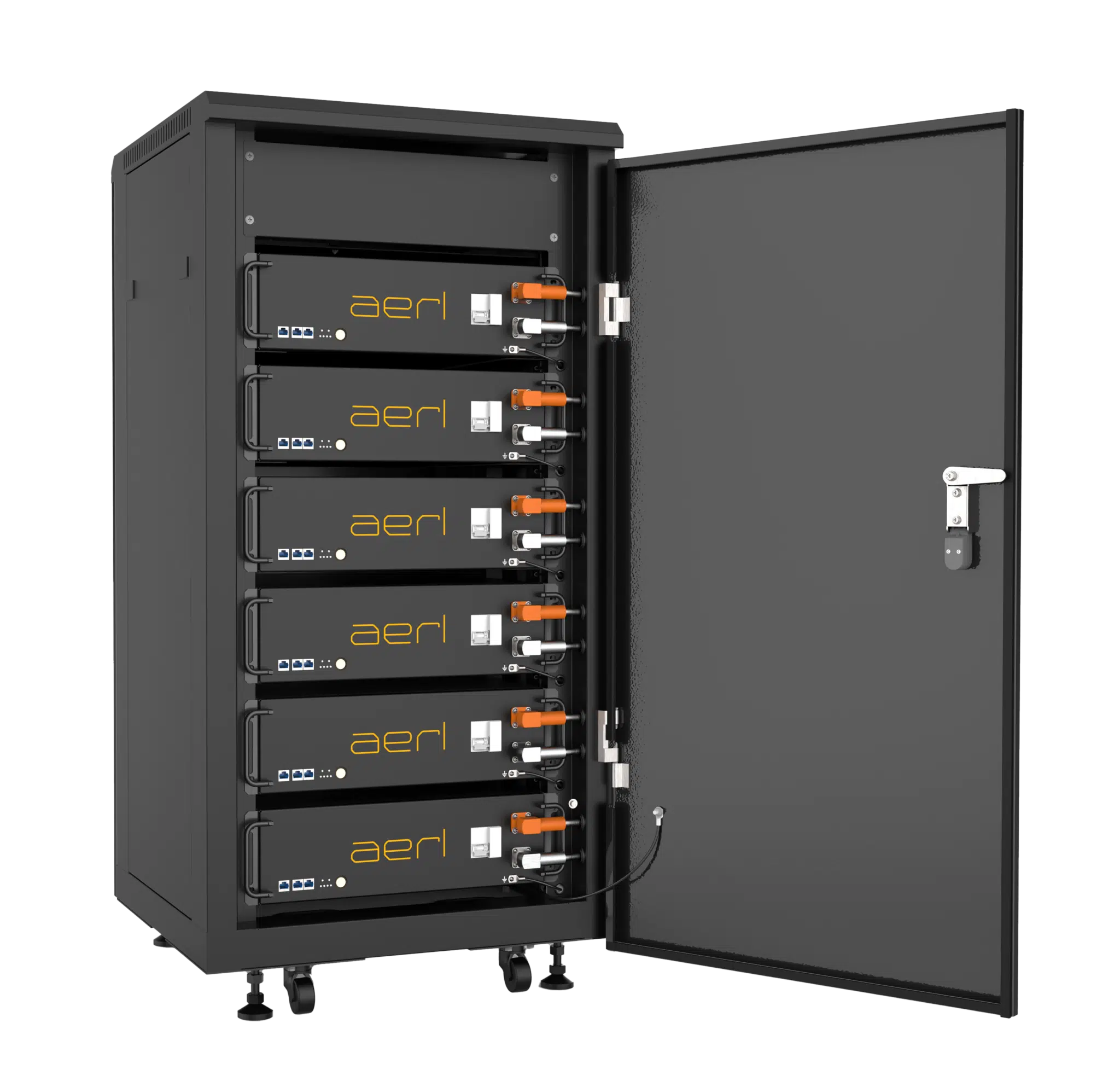
LiFe² 5120S · Managed (Comms) and Self-Managed (No Comms)
PCE Integration GuideRev 2.0.1, 8 Nov 2026
Download PDF· Rev 2.0.1
PCE Integration Guide
Inverter and Charger Settings
This guide covers only the battery's charge and discharge settings. All other configuration and system settings are the integrator's responsibility.
Before programming, the integrator must understand the Power Conversion Equipment (PCE) being used. AERL strongly recommends the PCE manufacturer's training or integration course, where one is available.
The LiFe² 5120S runs in Managed (Comms) or Self-Managed (No Comms) mode. This guide gives the settings for each mode and the minimum number of battery modules for specific inverters and chargers. Read it before you configure the system.
Installers and integrators are responsible for the system design. AERL is not responsible for designs that underperform or do not meet the expected standards.
Settings may change without notice. They are correct at the date of publication.
The minimum number of battery modules ensures that the batteries can support the full output of the connected PCE. In Managed mode, the PCE operates within the battery's limits. In Self-Managed mode, install at least the recommended minimum, or the battery may be operated outside its warranty conditions.
To size a complete LiFe² system (modules, cabinets and charge sources), see the AERL LiFe² 5120S System Sizing Guide, at aerl.com.au.
Follow the LiFe² 5120S Installation and Operation Manual, including all its environmental, installation and battery specifications.
The LiFe² 5120S works with selected inverters and chargers (PCE) in Managed mode, over a CAN bus connection. The battery sends its data to the PCE, which then sets the charge and discharge from the battery's cell temperature and state of charge. Managed mode extends cell life and keeps the State of Charge reporting accurate.
The PCE listed in this section support CAN bus communication. Follow each PCE manufacturer's instructions for connecting a managed battery.
| Charger | Battery modules |
|---|---|
| SRX 600/70-48 | 1 |
| SRX-R 600/60-48 | 1 |
Minimum number of LiFe² 5120S modules per inverter, from Victron's and ZYC's published tables.
| Inverter | Single-phase on-grid | Single-phase off-grid | Three-phase on-grid | Three-phase off-grid |
|---|---|---|---|---|
| MultiPlus 48/500/6 | 1 | 1 | 1 | 1 |
| MultiPlus 48/800/9 | 1 | 1 | 1 | 1 |
| MultiPlus 48/1200/13 | 1 | 1 | 1 | 1 |
| MultiPlus 48/1600/20 | 1 | 1 | 1 | 2 |
| MultiPlus 48/2000/25 | 1 | 1 | 1 | 2 |
| MultiPlus 48/3000/35 | 1 | 1 | 2 | 3 |
| MultiPlus 48/5000/70 | 1 | 2 | 2 | 4 |
| MultiPlus-II (GX) 48/3000/35-32 | 1 | 1 | 1 | 3 |
| MultiPlus-II (GX) 48/5000/70-50 | 1 | 2 | 2 | 4 |
| MultiPlus-II 48/3000/35-32 | 1 | 1 | 1 | 3 |
| MultiPlus-II 48/5000/70-50 | 1 | 2 | 2 | 4 |
| MultiPlus-II 48/8000/110-100 | 1 | 3 | 3 | 7 |
| MultiPlus-II 48/10000/140-100 | 2 | 3 | 3 | 8 |
| MultiPlus-II 48/15000/200-100 | 2 | 4 | 4 | 12 |
| Quattro 48/5000/70-100/100 | 1 | 2 | 2 | 4 |
| Inverter | Single-phase on-grid | Single-phase off-grid | Three-phase on-grid | Three-phase off-grid |
|---|---|---|---|---|
| Quattro 48/8000/110-100/100 | 1 | 3 | 2 | 7 |
| Quattro 48/10000/140-100/100 | 2 | 3 | 4 | 8 |
| Quattro 48/15000/200-100/100 | 2 | 4 | 4 | 12 |
| Quattro II 48/5000/70-50 | 1 | 2 | 2 | 4 |
| RS Smart Solar 48/6000 | 1 | 2 | 2 | 4 |
| Multi RS Solar 48/6000 | 1 | 2 | 2 | 4 |
| Multi RS Solar 48/6000 Dual Tracker | 1 | 2 | 2 | 4 |
| EasySolar-II 48/3000/35-32 MPPT 250/70 GX | 1 | 1 | 2 | 3 |
| EasySolar-II 48/5000/70-50 MPPT 250/100 GX | 1 | 2 | 2 | 4 |
| Inverter | Battery modules |
|---|---|
| SUN-3.6K-SG01LP1-EU | 2 |
| SUN-5K-SG01LP1-EU | 2 |
| SUN-7.6K-SG01LP1-EU | 3 |
| SUN-8K-SG01LP1-EU | 3 |
| SUN-12K-SG01LP1-EU | 4 |
| SUN-14K-SG01LP1-EU | 4 |
| SUN-16K-SG01LP1-EU | 5 |
| SUN-3.6K-SG03LP1-EU | 2 |
| SUN-4.6K-SG03LP1-EU | 2 |
| SUN-5K-SG03LP1-EU | 2 |
| SUN-5.5K-SG03LP1-EU | 2 |
| SUN-6K-SG03LP1-EU | 2 |
| SUN-5K-SG04LP3-EU | 2 |
| SUN-6K-SG04LP3-EU | 2 |
| SUN-8K-SG04LP3-EU | 3 |
| SUN-10K-SG04LP3-EU | 3 |
| SUN-12K-SG04LP3-EU | 4 |
| SUN-3K-SG04LP1-EU | 1 |
| Inverter | Battery modules |
|---|---|
| SUN-3.6K-SG04LP1-EU | 2 |
| SUN-5K-SG04LP1-EU | 2 |
| SUN-6K-SG04LP1-EU | 2 |
| SUN-3.6K-SG05LP1-EU | 2 |
| SUN-5K-SG05LP1-EU | 2 |
| SUN-6K-SG05LP1-EU | 2 |
| SUN-7K-SG05LP1-EU | 2 |
| SUN-7.6K-SG05LP1-EU | 3 |
| SUN-8K-SG05LP1-EU | 3 |
| Inverter | Battery modules |
|---|---|
| Ex9N-DH-3KS-AU | 1 |
| Ex9N-DH-3.6KS-AU | 1 |
| Ex9N-DH-5KS-AU | 2 |
| Ex9N-DH-6KS-AU | 2 |
| Ex9N-DH-7.6KS-AU | 3 |
| Ex9N-DH-8KS-AU | 3 |
| Ex9N-DH-5KT-AU | 2 |
| Ex9N-DH-6KT-AU | 2 |
| Ex9N-DH-8KT-AU | 3 |
| Ex9N-DH-10KT-AU | 3 |
| Ex9N-DH-12KT-AU | 4 |
In Self-Managed (No Comms) mode, the LiFe² 5120S works with PCE whose charge settings are programmed by hand. The PCE must allow its charge settings to be set to the battery's requirements.
The battery starts in Managed mode by default. To switch it to Self-Managed mode, double-press the ON/OFF button on the master battery with the battery on: the SOC LEDs flash 3 times to confirm, and the battery remembers the mode after a restart. It returns to Managed mode automatically when a communication cable to the inverter is connected.
This section gives the settings and minimum battery modules for common PCE brands. If your PCE is not listed, contact AERL for its settings.
| Parameter | Battery specification |
|---|---|
| Charge Voltage DC | 56 V |
| Max Charge Current | 70 A |
| Max Discharge Current | 100 A |
| Max Depth of Discharge | 90% (recommended setting) |
The battery can discharge to 100% (LiFe² 5120S datasheet and manual). 90% is the recommended setting: it gives a longer cycle life (see the cycle-life curves in the manual).
| Inverter | Single phase | Three phase |
|---|---|---|
| SPMC480 | 2 | 6 |
| SPMC481 | 2 | 6 |
| SPMC482 | 3 | 9 |
| Inverter | Tab | Input data |
|---|---|---|
| Battery Type | Quick Start | LiFePO4 |
| Battery Capacity | Quick Start | Total Ah Capacity of LiFe² 5120S installed |
| Voltage DC Shutdown 0% Load | Inverter | 49.50 V (10% SoC) |
| Voltage DC Shutdown 100% Load | Inverter | 46 V |
| Recovery Voltage | Inverter | 52 V |
| Shut Down SoC % | Inverter | 20% (minimum) |
| Max Charge Voltage | Battery | 56 V |
| High Battery Alert voltage | Battery | 58.3 V |
| High Battery Alert Clear | Battery | 57.3 V |
| Periodic Equalise | Battery | N/A |
| Periodic Recharge | Battery | 14 Days |
| Peukert's Exponent | Battery | 1.02 |
| Limit Charge Above °C | Battery | 50 °C |
| Limit Rate % | Battery | 0 |
| Max Charge Current % or Amp | Charger | 0.7C – 70% of total Ah Capacity Installed |
| Initial Return voltage | Charger | 52.8 V |
| Initial Return SoC | Charger | 95% |
| Initial Stage Voltage | Charger | 54 V |
| Initial Stage Current | Charger | 100% |
| Initial Stage Time | Charger | 40 min |
| Bulk Stage Voltage | Charger | 55 V |
| Bulk Stage Current | Charger | 20% |
| Bulk stage Time | Charger | 30 min |
| Absorb Stage Voltage | Charger | 55 V |
| Absorb Stage Current | Charger | 10% |
| Absorb – Float Transition Net Change | Charger | 1% |
| Absorb – Float Transition Change Time | Charger | 5 min |
| Absorb – Float Max Time | Charger | 10 min |
| Float Stage Voltage | Charger | 55 V |
| Long Term Float Voltage | Charger | 55 V |
| Equalise Stage Voltage | Charger | 55 V |
| Equalise Current | Charger | 10% |
| Inverter | Tab | Input data |
|---|---|---|
| Equalise Time | Charger | 1 h |
| Min Temp Compensation °C | Charger | N/A |
| Max Temp Compensation °C | Charger | N/A |
| Ref A Temp Compensation mV/cell/°C | Charger | N/A |
| Ref B Temp Compensation mV/cell/°C | Charger | N/A |
| Inverter | Single phase | Three phase |
|---|---|---|
| RHI-3K-48ES-5G | 1 | — |
| RHI-3.6-48ES-5G | 1 | — |
| RHI-4.6K-48ES-5G | 2 | — |
| RHI-5K-48ES-5G | 2 | — |
| RHI-6K-48ES-5G | 2 | — |
| RAI-3K-48ES-5G | 1 | — |
| S5-EH1P3K-L | 1 | — |
| S5-EH1P3.6K-L | 1 | — |
| S5-EH1P4.6K-L | 2 | — |
| S5-EH1P5K-L | 2 | — |
| S5-EH1P6K-L | 2 | — |
| S5-EO1P4K-48 | 2 | — |
| S5-EO1P4K-48-P | 2 | — |
| S5-EO1P5K-48 | 2 | — |
| S5-EO1P5K-48-P | 2 | — |
| S6-EO1P4K-48 | 2 | 4 |
| S6-EO1P5K-48 | 2 | 5 |
| S6-EH1P3K-L-EU | 1 | 3 |
| S6-EH1P3.6K-L-EU | 2 | 4 |
| S6-EH1P4.6K-L-EU | 2 | 4 |
| Inverter | Single phase | Three phase |
|---|---|---|
| S6-EH1P5K-L-EU | 2 | 5 |
| S6-EH1P6K-L-EU | 2 | 6 |
| S6-EH1P3K-L-PRO | 1 | 3 |
| S6-EH1P3.6K-L-PRO | 2 | 4 |
| S6-EH1P5K-L-PRO | 2 | 5 |
| S6-EH1P6K-L-PRO | 2 | 6 |
| S6-EH1P8K-L-PRO | 3 | 7 |
| Setting | Input data |
|---|---|
| Battery Type | Lead Acid Battery |
| Battery Capacity | Total Ah Capacity of LiFe² 5120S Installed |
| Floating Voltage | 56 V |
| I_Max Discharge | Max. 100 A per battery installed |
| I_Max Charge | Max. 70 A per battery installed |
| Equalize Voltage | 56 V |
| Over Discharge Voltage | 50.2 V |
| Force Charge Voltage | 48 V |
| ForceChg PLmt | Max. 3500 W per battery installed |
| Temp. Compensation | 0 |
| AMB. Temp.Lower | 5 °C |
| AMB. Temp.Upper | 45 °C |
| Power Limit On | From Grid |
Select Save and Send, then set Environment Temp to Warm.
| Inverter | Single phase | Three phase |
|---|---|---|
| SI 4.4M | 2 | 6 |
| SI 6.0H | 2 | 6 |
| SI 8.0H | 3 | 9 |
AERL strongly recommends an external shunt to measure the state of charge: with SMA inverters it improves SOC accuracy. See the SMA manuals for instructions.
| Setting | Input data |
|---|---|
| Battery Type | Valve Regulated Lead Acid |
| Nominal Battery Voltage | 48 V |
| Nominal Battery Capacity | Total Ah Capacity of LiFe² 5120S Installed |
| Device Configuration | Charge |
| Maximum Charging Current | 0.7C – 70% of Total Ah Capacity Installed |
| Time for Boost | 2 Hours |
| Time for Equalisation Charge | 2 Hours |
| Time for Full Charge | 2 Hours |
| Discharge Cut Off Voltage | 49.5 V |
| Maximum discharge Current | Leave Default |
| Cell Charge Nominal for Boost Charge | 2.35 V |
| Cell Charge Nominal for Full Charging | 2.35 V |
| Cell Charge Nominal for Equalisation Charge | 2.35 V |
| Float Voltage Cyclic Applications | 2.35 V |
| Float Voltage UPS/Standby Applications | 2.33 V |
| Cycle Time Full Charge | 7 Days |
| Cycle Time Equalisation Charge | 30 Days |
| Battery Temperature Compensation | 0 mV/°C (per cell) |
| Setting | Input data |
|---|---|
| Automatic Equalisation Charge | Disable (OFF) |
| Voltage Setpoint with Deactivated BMS | 56 V |
| Protection Mode | |
| Start Time A | Default |
| Start Time B | Default |
| End Time A | Default |
| End Time B | Default |
| Limit of Battery State of Charge A | 30% |
| Limit of Battery State of Charge B | 25% |
| Limit of Battery State of Charge C | 20% |
AERL strongly recommends an external shunt to measure the state of charge: with SMA inverters it improves SOC accuracy. See the SMA manuals for instructions.
| Setting | Section | Input data |
|---|---|---|
| Battery Type | Basic | Valve Regulated Lead Acid |
| Nominal Battery Voltage | Basic | 48 V |
| Nominal Battery Capacity | Basic | Total Ah Capacity of LiFe² 5120S Installed |
| 222.01 BatChrgCurMax | Installer Mode | 0.7C – 70% of Total Ah Capacity Installed |
| 222.02 AptTmBoost | Expert Mode | 120 min |
| 222.03 AptTmFul | Expert Mode | 2 Hours |
| 222.04 AptTmEqu | Expert Mode | 2 Hours |
| 222.05 CycTmFul | Expert Mode | 7 Days |
| 222.06 CycTmEqu | Expert Mode | 30 Days |
| 222.07 ChrgVtgBoost | Expert Mode | 2.35 V |
| 222.08 ChrgVtgFul | Expert Mode | 2.35 V |
| 222.09 ChrgVtgEqu | Expert Mode | 2.35 V |
| 222.10 ChrgVtgFlo | Expert Mode | 2.35 V Cyclic / 2.33 V Standby |
| Setting | Section | Input data |
|---|---|---|
| 222.11 BatTmpCps | Expert Mode | 0 mV/°C (per cell) |
| 222.12 AutoEquChrgEna | Expert Mode | Disable (OFF) |
| 222.13 BatChrgVtgMan | Expert Mode | 56 V |
| 223.01 BatPro1TmStr | 223# Protection | Default |
| 223.02 BatPro1TmStp | 223# Protection | Default |
| 223.03 BatPro2TmStr | 223# Protection | Default |
| 223.04 BatPro2TmStp | 223# Protection | Default |
| 223.05 BatPro1Soc | 223# Protection | 30% |
| 223.06 BatPro2Soc | 223# Protection | 25% |
| 223.07 BatPro3Soc | 223# Protection | 20% |
If you have any questions or need support, contact AERL.
Sincerely,
The AERL Team
AERL Pty Ltd · 1/75 Bluestone Circuit, Seventeen Mile Rocks QLD 4073 · 1800 950 865 · [email protected] · aerl.com.au
Australian Energy Research Laboratories
1/75 Bluestone Circuit
Seventeen Mile Rocks QLD 4073
Australia