

All‑In‑One Energy Storage System
Commercial Outdoor Energy Storage, 25–50 kW
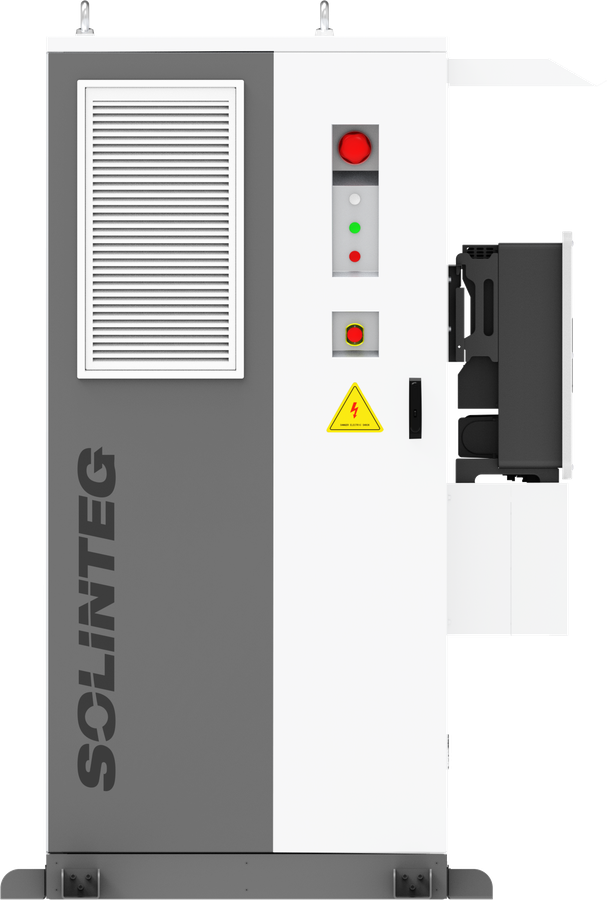
AIO-25K · 29.9K · 30K · 40K · 50K
Quick Start GuideRev 1.0.1, 8 Nov 2026
Commercial Outdoor Energy Storage, 25–50 kW
This guide covers the essential steps to install, connect and start up the All-In-One. It does not replace the All-In-One User Manual. Read the manual's safety instructions (§1) before you start, and use the manual for any step you are unsure of. References such as §5.3 point to sections of the user manual.

Install in accordance with AS/NZS 3000, AS/NZS 5139, AS/NZS 4777.1 and the requirements of the local network service provider. Never work on live equipment: isolate every supply first. Connect the protective earth before anything else, and disconnect it last.
The cabinet holds up to 112.5 kWh of lithium-ion batteries at high DC voltage (up to 840 V). Never short-circuit the battery terminals. Do not install, wire or open the cabinet in rain, snow, lightning or high humidity.
| Item | Value | Manual |
|---|---|---|
| Cabinet size (W × H × D) | 1050 × 2262 × 1140 mm (cabinet alone); 1376 mm wide with the inverter fitted | §2.2 |
| Weight | Cabinet 1101–1440 kg; inverter 89 kg | About, §4.1.2 |
| Crane or forklift capacity | At least 2 t; crane working radius at least 2 m | §3.2 |
| Foundation | Level within 3 mm; slope no more than 5° | §4.1.2 |
| Anchor holes | 25 mm diameter, 150 mm deep, M20 × 150 anchors | §4.2.1 |
| Earth | 40 × 4 mm galvanised flat bar or 50 mm² PE; M8 × 16 bolts at 8 N·m | §5.2 |
| Grid cable | 4 × 35 + 1 × 16 mm² or 4 × 50 + 1 × 16 mm²; SC50-8 lugs at 12 N·m | §5.3.3 |
| Load cable | 4 × 25 + 1 × 16 mm² or 4 × 35 + 1 × 16 mm²; C45-25 lugs at 3.5 N·m | §5.3.3 |
| PE lugs (grid and load) | SC16-8 at 12 N·m | §5.3.3 |
| Grid and load strip lengths | Sheath 95–100 mm; cores 20–25 mm | §5.3.3 |
| Inverter on-grid connector | Terminal screws 3.8 N·m; nut 10 N·m | §5.3.1 |
| Inverter back-up connector | Strip sheath 95–100 mm, cores 15 mm; screws 5 N·m; nut 10 N·m | §5.3.1 |
| Battery voltage before connecting | 840 V or less | §5.3.1 |
| PV cable | 4 mm² or 6 mm² | §5.3.1 |
| Emergency stop and fire signal cores | 0.5–1.5 mm²; strip sheath 55 mm, cores 8 mm | §5.3.1, §5.3.4 |
| Operating temperature | −20 to 50 °C (charging 0 to 50 °C) | §4.1.3 |
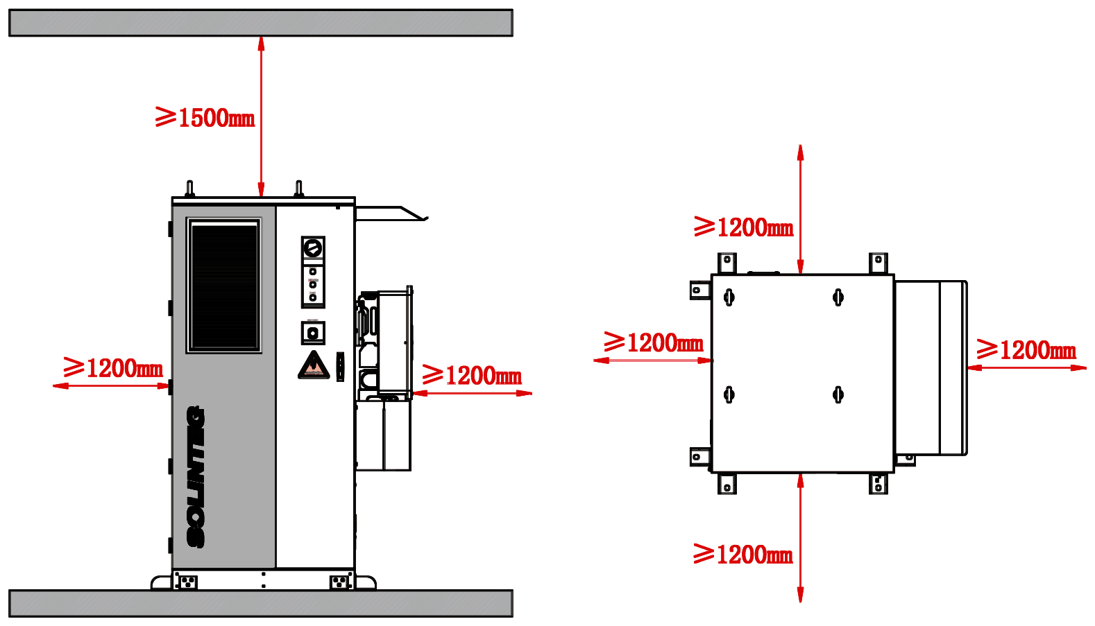
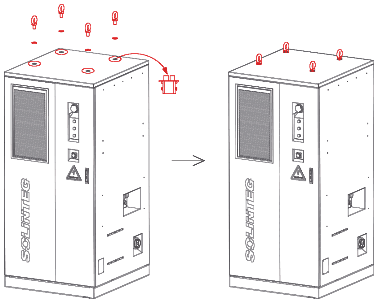
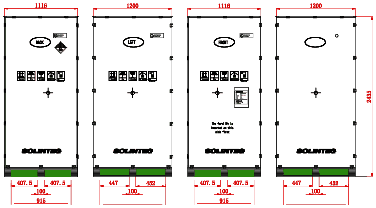
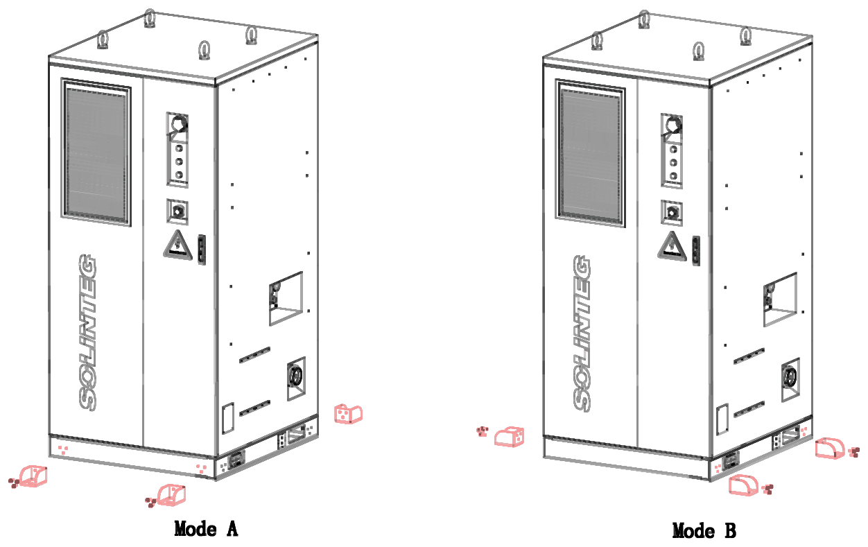
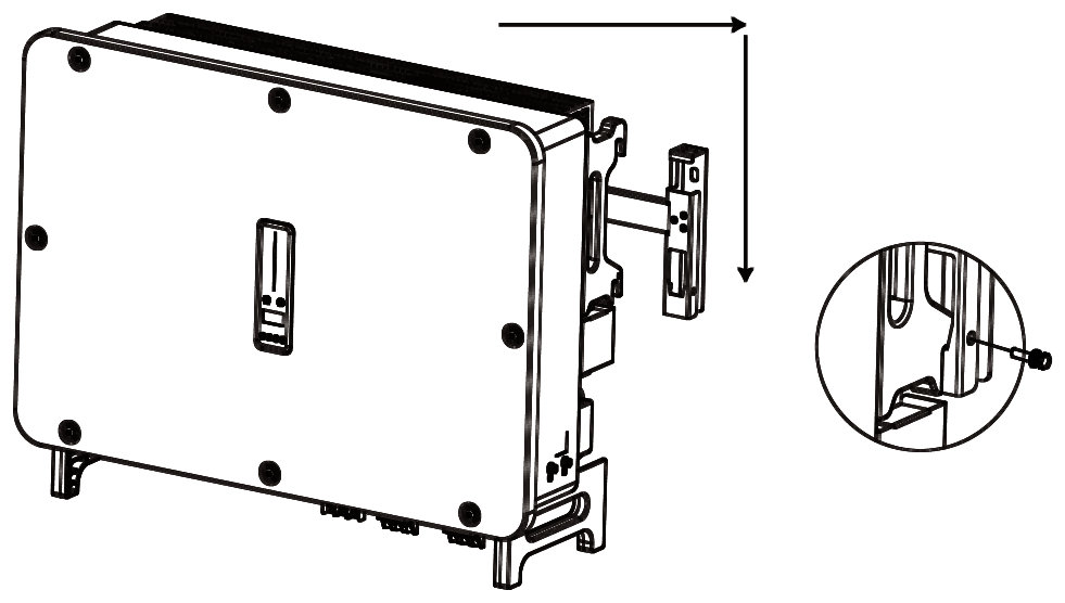
Switch off every breaker in the cabinet and turn the inverter DC switch OFF. Connect the cabinet earth first. Leave the waterproof plugs in unused cable entries, and seal every entry when you finish.
Connect the earth point on the right of the cabinet to the site earthing system with 40 × 4 mm galvanised flat bar or 50 mm² PE cable, using two M8 × 16 bolts at 8 N·m. Paint cut ends of the flat bar (§5.2).
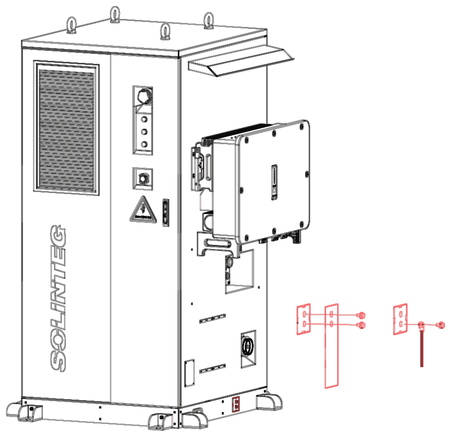
The cables from the cabinet to the inverter are supplied and already connected inside the cabinet. Loosen the glands on the side cable panel and pull each cable out far enough to reach the inverter.
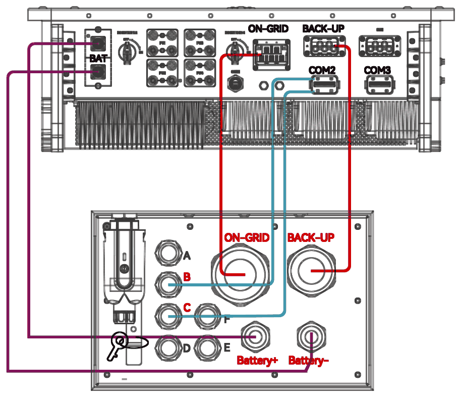
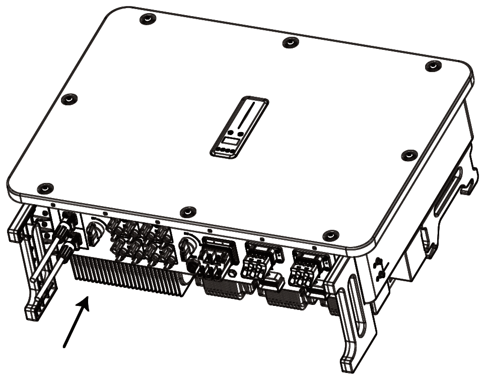
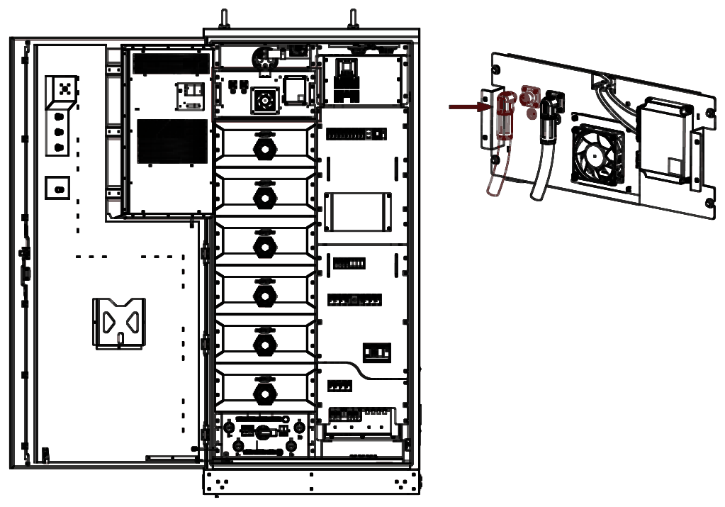
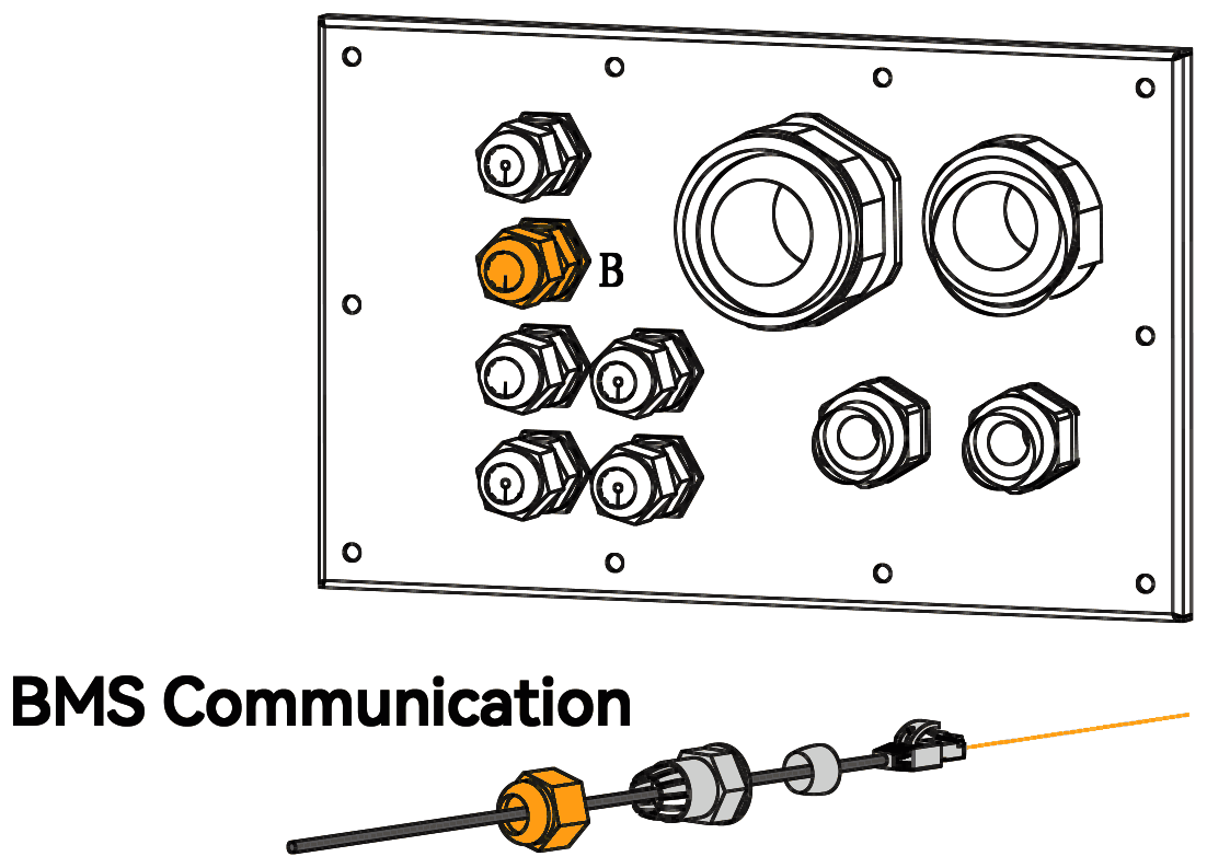
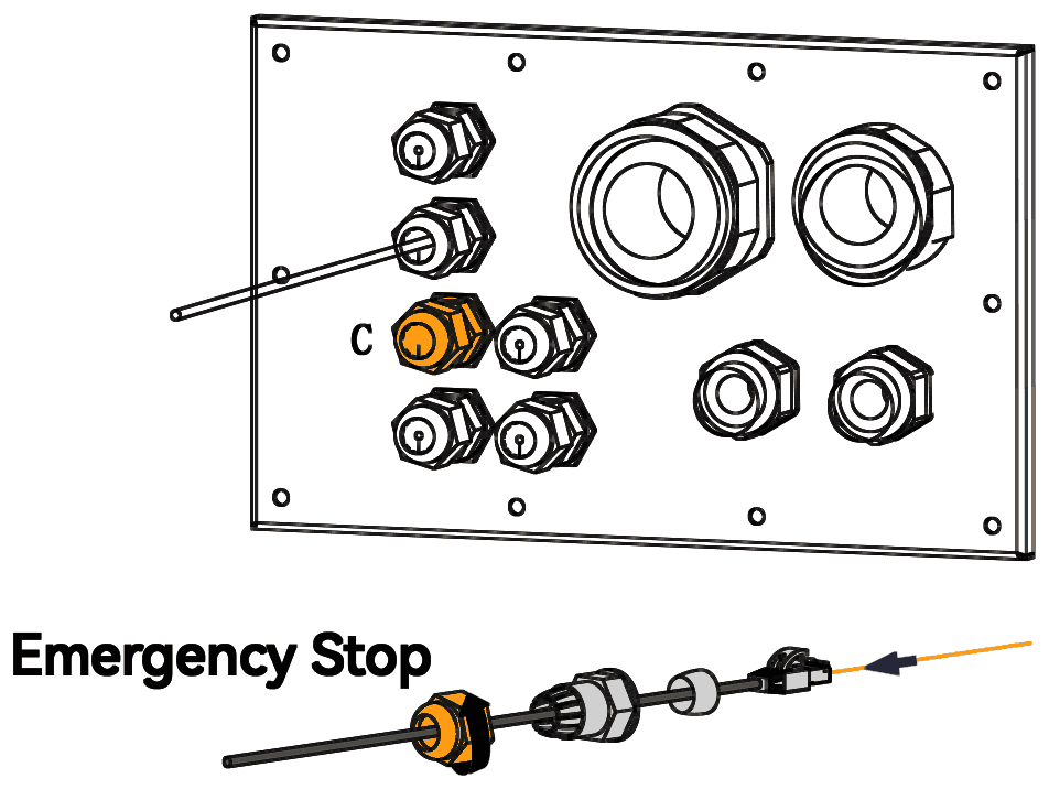
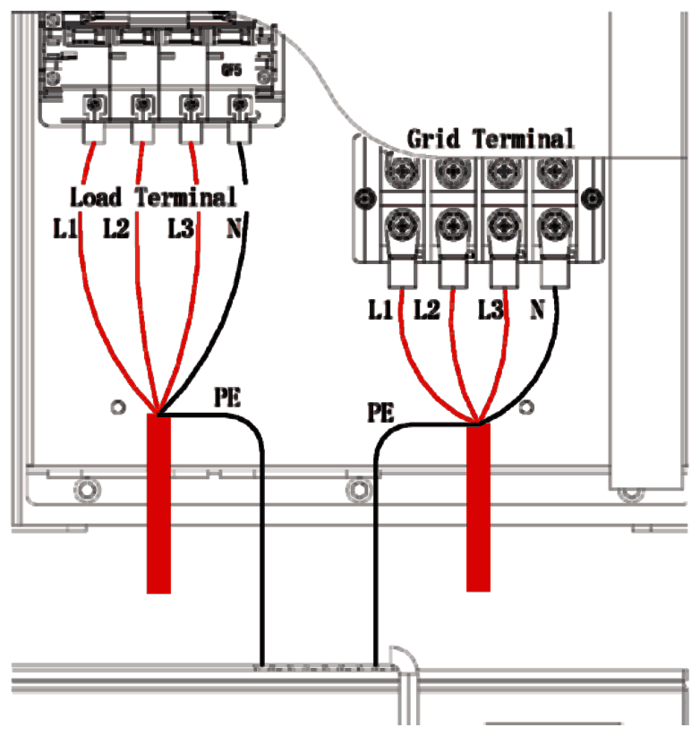
Tie the cables to the tie bar and fit the cable cover after commissioning (§5.3.1). Close and lock the cabinet door.
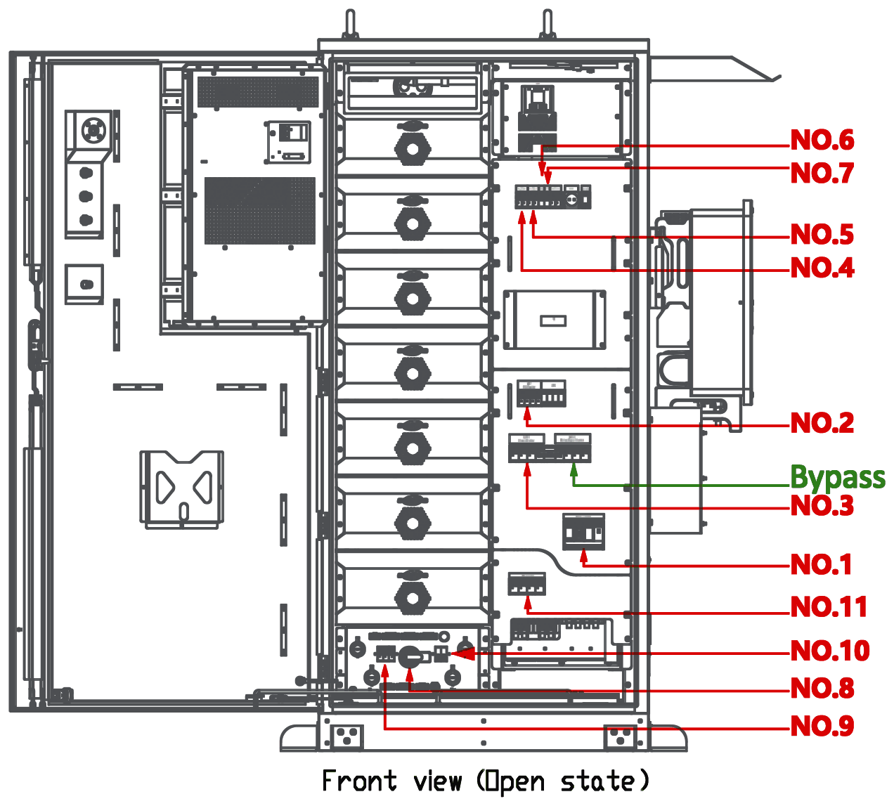
Switch on the breakers in this order (§6.1).
| Step | Breaker | Result |
|---|---|---|
| 1 | QF4 grid | Grid power on; white power indicator on |
| 2 | QF7 SPD | Surge protection in service |
| 3 | QF6-1 bypass | AC system in service |
| 4 | QF8 auxiliary main | Control circuits powered |
| 5 | QF81 air conditioner | Air conditioner starts |
| 6 | QF82 UPS | UPS starts. The first time, press the UPS power button |
| 7 | QF821 controller PDU | PDU control supply on |
| 8 | QF1 high-voltage box main | BMS powers up |
| 9 | QF3 high-voltage box DC | DC control supply on |
| 10 | QF2 high-voltage box AC | AC control supply on |
| 11 | — | BMS self-test. Green running indicator on; red fault indicator off |
| 12 | — | The inverter runs its grid self-test and starts on-grid operation |
| 13 | QF5 load | Check the loads are ready, then switch on. Start-up complete |
| Indicator | Running normally |
|---|---|
| Cabinet power (white) | On steady |
| Cabinet running (green) | On steady |
| Cabinet fault (red) | Off |
| Audible and visual alarm | Silent |
| High-voltage box fault (red) | Off |
| Inverter power (blue) | Breathing |
| Inverter grid | On steady (on-grid operation) |
| Inverter communication | Green (red means no BMS communication) |
If a fault indicator is on, see section 06 of this guide and §7.3 of the user manual.
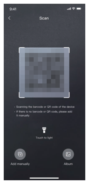
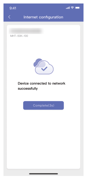
Scan a code to install the free Solinteg IntegHub app, or search for IntegHub in Google Play or the App Store.


Step-by-step screenshots are in §6.2.4 of the user manual.

Press the emergency stop button on the door and switch off grid breaker QF4. Switch off QF821 as well if the UPS output must be cut (§6.1).
| Code | Meaning | First check |
|---|---|---|
| E400 | No BMS communication | Battery type selected in the inverter; cable in BMS 1 (not BMS 2); RJ45 pinout |
| E401 | Battery over-discharged | Battery power and comms connections; PV, grid and generator connections; load size |
| E403 | BMS sleeping | Grid or PV supply is stable; battery-to-inverter power connection |
| E431 | Battery voltage mismatch over 100 V | Power cable connections and damage |
| E421 / E423 | Too cold to charge / discharge | Battery temperature reading and sensors; warm the battery, then restart it |
| E422 / E424 | Too hot to charge / discharge | Battery temperature reading and sensors; cool the battery, then restart it |
The full list of protection (E), alarm (I) and warning (W) codes is in §7.3 of the user manual.
1800 950 865 · [email protected] · aerl.com.au
Have ready: the model and the cabinet serial number, the inverter serial number and firmware, any alarm codes, and photos of the installation and indicators.
Australian Energy Research Laboratories
1/75 Bluestone Circuit
Seventeen Mile Rocks QLD 4073
Australia