

All‑In‑One Energy Storage System
Commercial Outdoor Energy Storage, 25–50 kW, 64.3–112.5 kWh
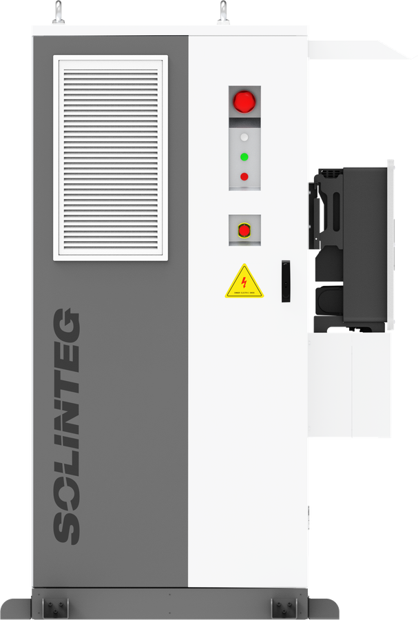
AIO-25K · 29.9K · 30K · 40K · 50K
User ManualRev 1.0.1, 8 Nov 2026
Commercial Outdoor Energy Storage, 25–50 kW, 64.3–112.5 kWh
This manual covers the safety instructions, product description, transport, storage, installation, electrical connection, commissioning, maintenance and troubleshooting of the All-In-One energy storage system.
The All-In-One is manufactured by Solinteg. It combines a Solinteg E2BR outdoor air-cooled battery cabinet (the "cabinet" in this manual) with a Solinteg M2HT 25–50 kW hybrid inverter mounted on the side of the cabinet. The model (AIO-25K to AIO-50K) sets the inverter power, and the cabinet sets the storage capacity:
| Storage option | 64 kWh | 80 kWh | 96 kWh | 112 kWh |
|---|---|---|---|---|
| Solinteg cabinet model | E2BR-S64K-C | E2BR-S80K-C | E2BR-S96K-C | E2BR-S112K-C |
| System energy | 64.3 kWh | 80.3 kWh | 96.4 kWh | 112.5 kWh |
| Usable energy | 57.87 kWh | 72.27 kWh | 86.76 kWh | 101.25 kWh |
| Ingress protection | IP55 | IP55 | IP55 | IP55 |
| Cabinet dimensions (W × H × D) | 1050 × 2262 × 1140 mm | 1050 × 2262 × 1140 mm | 1050 × 2262 × 1140 mm | 1050 × 2262 × 1140 mm |
| Weight | 1101 ± 22 kg | 1214 ± 24 kg | 1327 ± 26 kg | 1440 ± 28 kg |
This manual is for licensed electrical workers who install, operate and maintain the cabinet. Anyone working on the cabinet must:
Only people who meet all of these requirements may install, maintain or troubleshoot the cabinet.
This manual uses the following symbols. Read and follow every instruction they mark.

Indicates a hazard with a high level of risk that, if not avoided, will result in death or serious injury.
Indicates a hazard with a medium level of risk that, if not avoided, could result in death or serious injury.

Indicates a hazard with a low level of risk that, if not avoided, could result in minor or moderate injury, or damage to equipment.

Extra information to help you use the equipment efficiently. Notes are not safety warnings.
This manual is based on Solinteg's E2BR user manual. AERL has rewritten the text for clarity and adapted it for Australia. The product specifications are Solinteg's. Illustrations are for reference only and may differ from your product. The manual may be updated as the product changes. Download the latest edition from aerl.com.au.
Nothing in this manual excludes, restricts or modifies any right or remedy you have under the Australian Consumer Law.
Before you transport, store, install, operate or maintain the equipment, read this manual carefully and follow it, the labels on the equipment and every safety instruction in this manual.
The manufacturer's warranty does not cover damage caused by:
To avoid injury, death or damage to the equipment, read these precautions before you start work.
The All-In-One is a commercial energy storage system, manufactured by Solinteg. Its Solinteg E2BR cabinet combines a high-capacity battery, a high-voltage box, an electrical compartment and a fire-protection system. With the Solinteg M2HT hybrid inverter mounted on its side, it forms an outdoor energy storage system that is easy to install and expand. It suits a wide range of commercial and industrial applications.
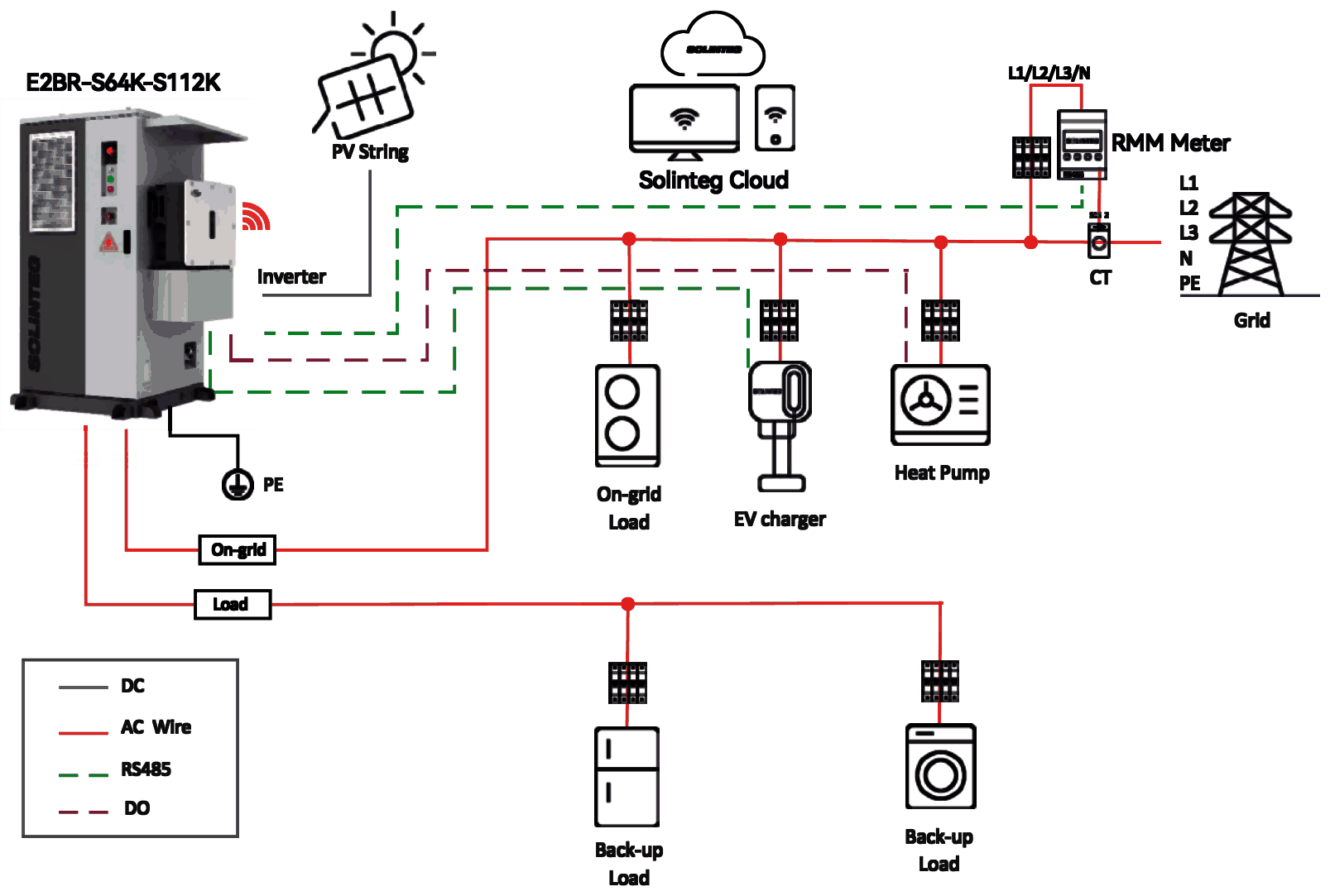
| Equipment | Description |
|---|---|
| Battery cabinet (Solinteg E2BR-S64/80/96/112K-C) | Outdoor air-cooled energy storage cabinet. Stores energy and provides stable backup power. |
| Hybrid inverter (Solinteg M2HT 25–50 kW) | PV and battery hybrid inverter. Converts DC to AC and manages energy flow. |
| Smart meter and CTs (RMM meter) | Measures power and communicates with the inverter, which uses the data to control battery charging and discharging and export to the grid. |
| EV charger | Charges electric vehicles. Solinteg chargers can communicate with Solinteg inverters. |
| Equipment | Description |
|---|---|
| Solinteg Cloud | Remote monitoring platform. View system data at any time. |
| Loads and heat pump | The system can control SG Ready heat pumps, configured by the user to suit the site. |
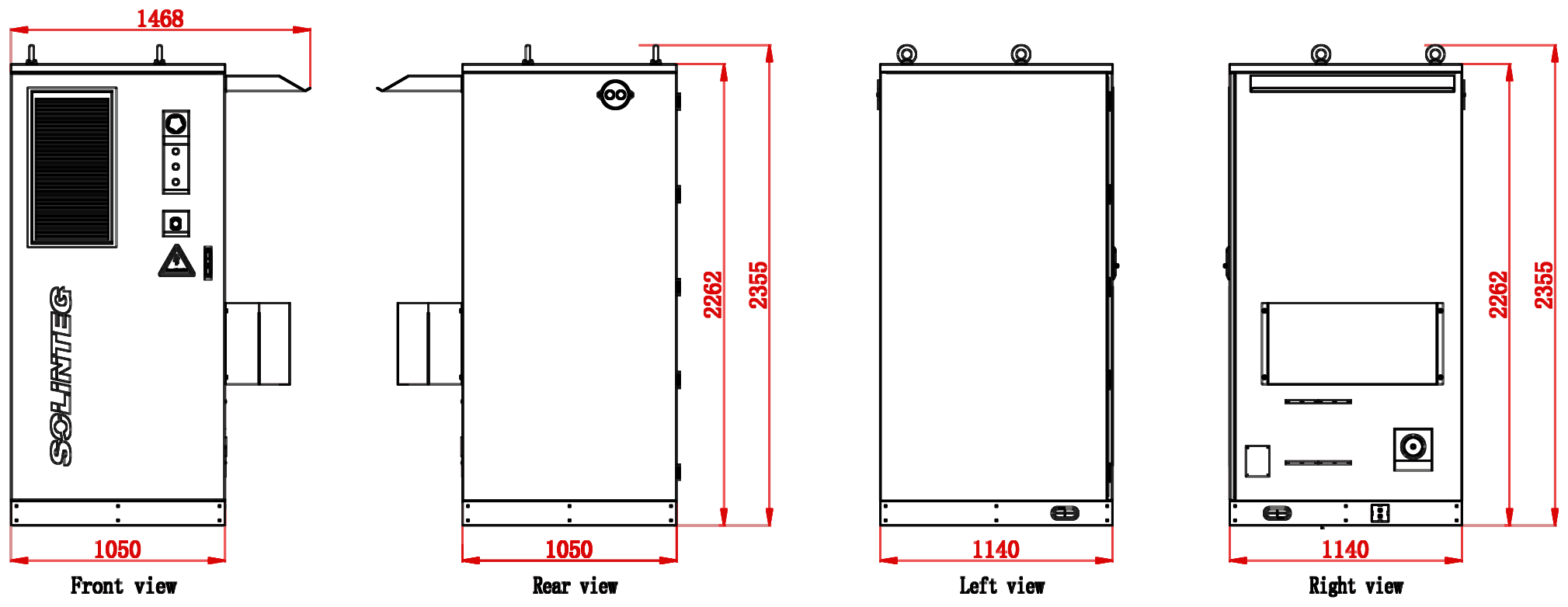
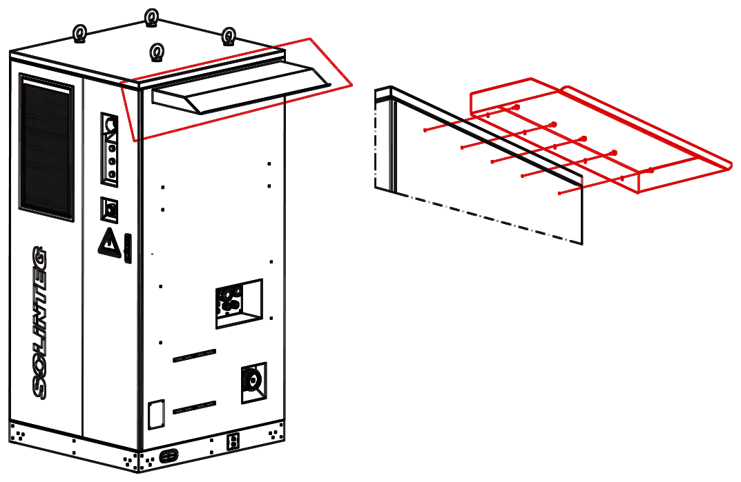
The cabinet alone measures 1050 × 2262 × 1140 mm (W × H × D). With the inverter fitted the system is 1376 mm wide, and with the rain shelter 1468 mm. The lifting eyes add 93 mm to the height (2355 mm).
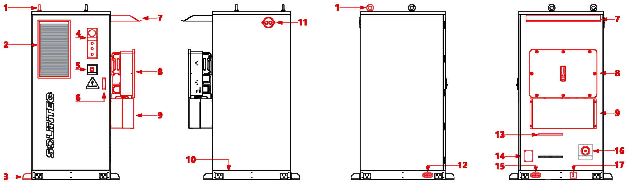
| No. | Name | Description |
|---|---|---|
| 1 | Lifting eye | For lifting the cabinet |
| 2 | Air outlet, cooling system | Air-conditioner air inlet and outlet |
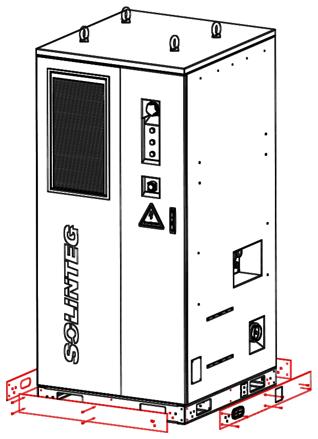
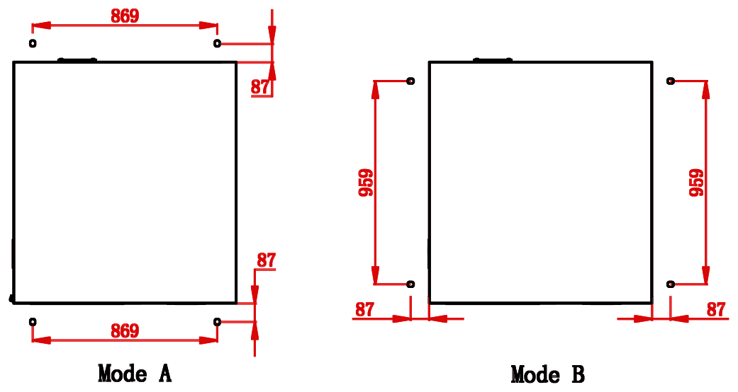
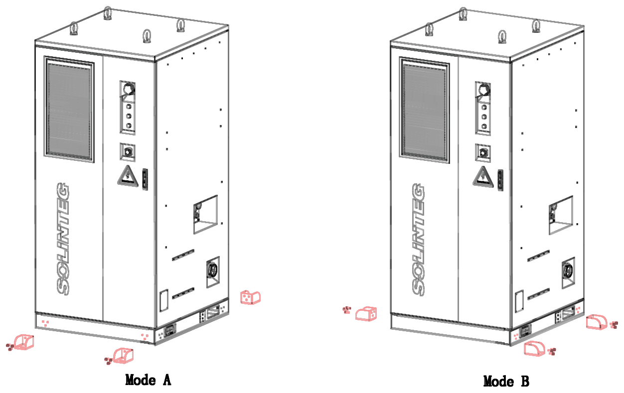
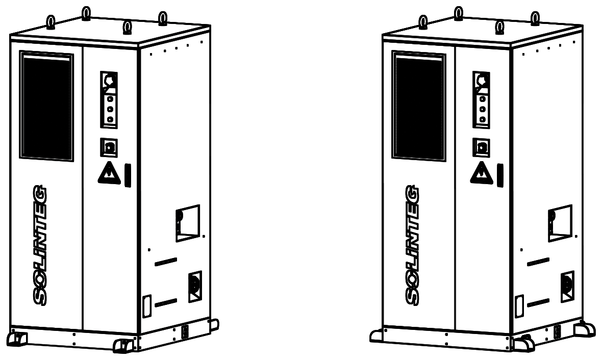
| 3 | Mounting foot* | For anchoring the cabinet |
| 4 | Operation indicators | Show system operating and fault status |
| No. | Name | Description |
|---|---|---|
| 5 | Emergency stop button | For an emergency stop |
| 6 | Door lock | Locks and opens the cabinet door |
| 7 | Rain shelter | Protects the inverter from rain and snow |
| 8 | Inverter** | 25–50 kW hybrid inverter |
| 9 | Cable cover | Protects the cables |
| 10 | Decorative panels | Trim around the base of the cabinet |
| 11 | Explosion-relief vents | Release gas pressure |
| 12 | Left cable entry | For cable routing |
| 13 | Cable clamp | For securing cables |
| 14 | Rating plate | Product specifications |
| 15 | Right cable entry | For cable routing |
| 16 | Fire-water inlet | For connecting an external fire-water supply |
| 17 | Cabinet earth point | Protective earth for the cabinet enclosure |
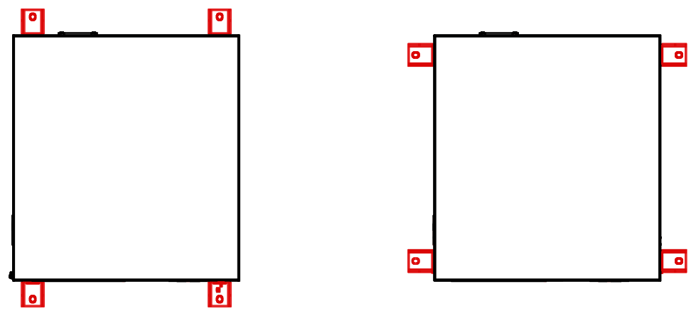
* Mounting feet can be fitted on any of the four sides. Fit them on the left and right, or front and rear, to suit the site.
** The cabinet provides a mounting position for one inverter, which makes installation and wiring easier. In the illustrations, the inverter is mounted on the side of the cabinet.
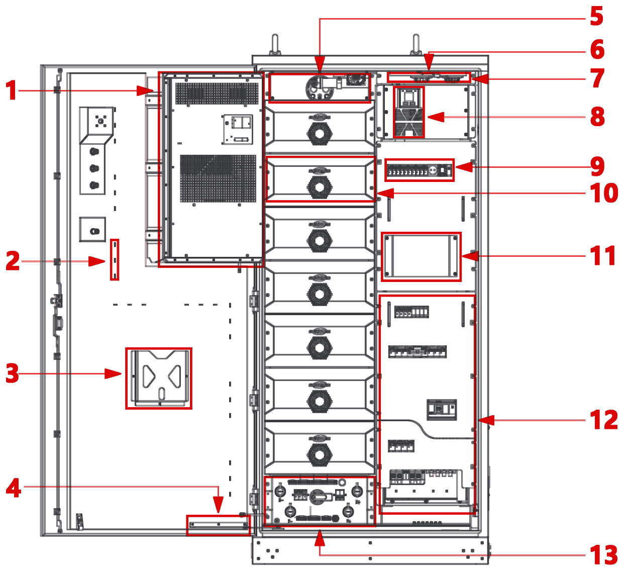
| No. | Name | Description |
|---|---|---|
| 1 | Air conditioner | Controls the temperature and humidity inside the cabinet |
| 2 | Cable tie bar | For tying cables |
| 3 | Document holder | Holds the cabinet documents |
| 4 | Door stay | Holds the front door open in wind |
| 5 | Fire-protection system | Temperature, gas and smoke detectors with automatic fire suppression |
| 6 | Sensors | Temperature and smoke sensors |
| 7 | Door switch and lighting | Door limit switch and cabinet lighting |
| 8 | UPS | Keeps critical control circuits in the cabinet powered |
| 9 | Control power supply | Control switches for the high-voltage box, air conditioner, UPS and service socket |
| 10 | Battery pack | Stores energy |
| 11 | Spare space | Space for future expansion |
| 12 | Electrical compartment | Power distribution for the cabinet |
| 13 | High-voltage box (master control) | Collects battery and fire data and controls the cabinet |
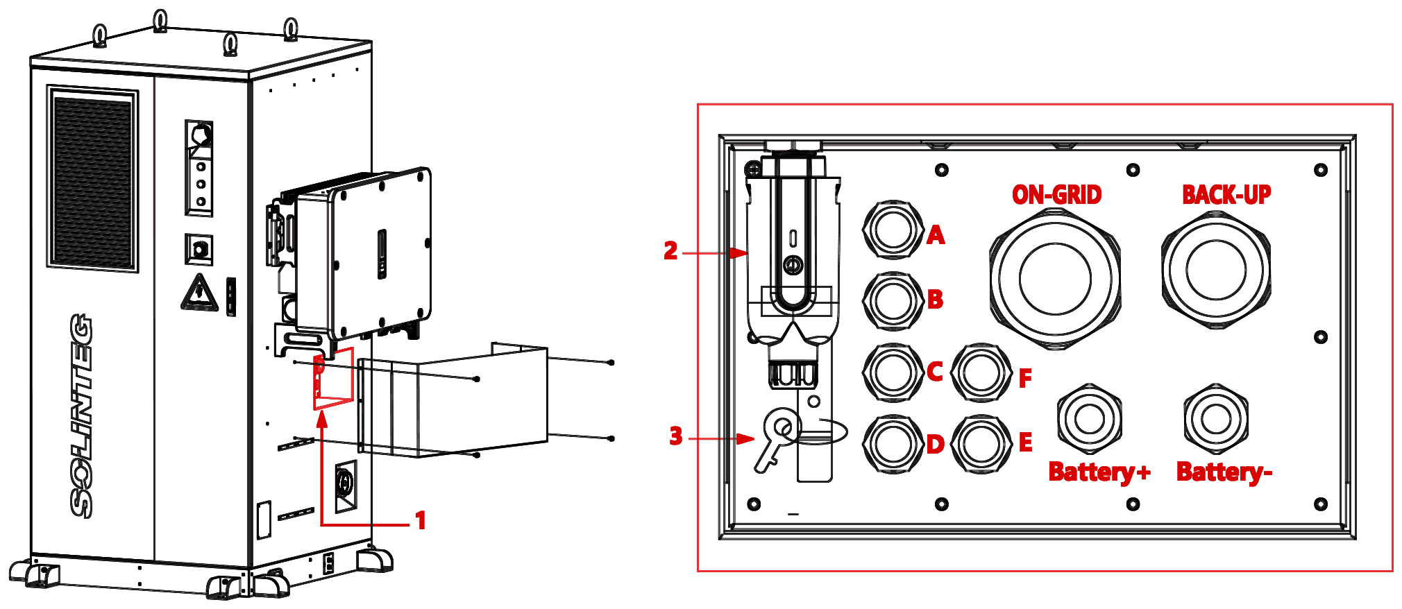
| No. | Name | Description |
|---|---|---|
| 1 | Side cable panel | Cable pass-through between the inverter and the cabinet |
| 2 | Communication port panel | Communication connections between the cabinet and the inverter |
| 3 | Cabinet key | Key for the cabinet door |
| No. | Name | Description |
|---|---|---|
| 4 | On-grid | Cable entry for the inverter on-grid cable |
| 5 | Back-up | Cable entry for the inverter back-up (load) cable |
| 6 | Battery + | Cable entry for the battery positive cable to the inverter |
| 7 | Battery − | Cable entry for the battery negative cable to the inverter |
| 8 (A) | Spare | Spare port |
| 9 (B) | Inverter comms | Communication between the inverter and the battery (BMS) |
| 10 (C) | Inverter emergency stop | Emergency stop signal to the inverter |
| 11 (D) | Spare | Spare port |
| 12 (E) | Spare | Spare port |
| 13 (F) | Spare | Spare port |
The cabinet door key is stored here. Remove it after unpacking.
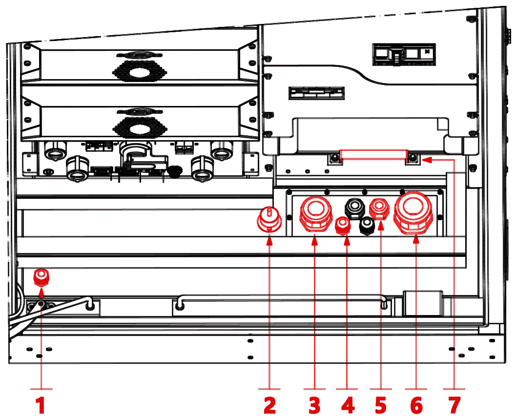
| No. | Name | Description |
|---|---|---|
| 1 | Air-conditioner drain | External drain for the air conditioner |
| 2 | Flood sensor | Detects water in the cabinet |
| No. | Name | Description |
|---|---|---|
| 3 | Load cable entry | Entry for the load cable |
| 4 | Cable entry | Spare cable entry |
| 5 | Cable entry | Cable entry |
| 6 | Grid cable entry | Entry for the grid cable |
| 7 | PE | Earth cable connection |
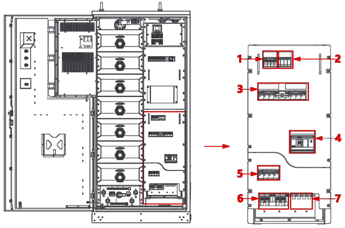
| No. | Label | Description |
|---|---|---|
| 1 | QF7 | Surge protection device (SPD) breaker |
| 2 | SPD | AC surge protection device |
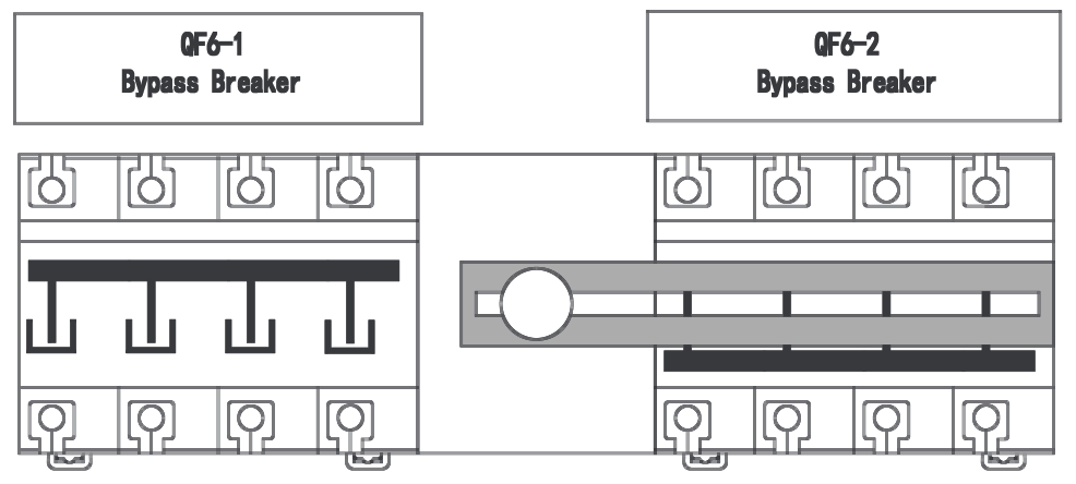
| 3 | QF6-1 / QF6-2 | Bypass breakers (switch between normal operation and maintenance bypass) |
| 4 | QF4 | Grid breaker |
| 5 | QF5 | Load breaker, with load terminals |
| 6 | — | Spare |
| 7 | Grid terminals | Grid terminals L1, L2, L3, N |
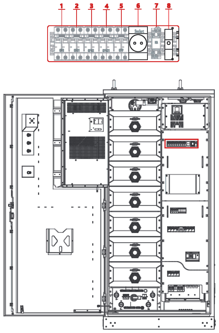
| No. | Label | Description |
|---|---|---|
| 1 | QF8 | Auxiliary main breaker |
| 2 | QF81 | Air-conditioner breaker |
| 3 | QF82 | UPS breaker |
| 4 | QF821 | Controller PDU AC breaker |
| 5 | QF9 | Socket breaker |
| 6 | Socket | Service socket |
| 7 | KA | Fire-signal relay |
| 8 | — | Spare breaker |
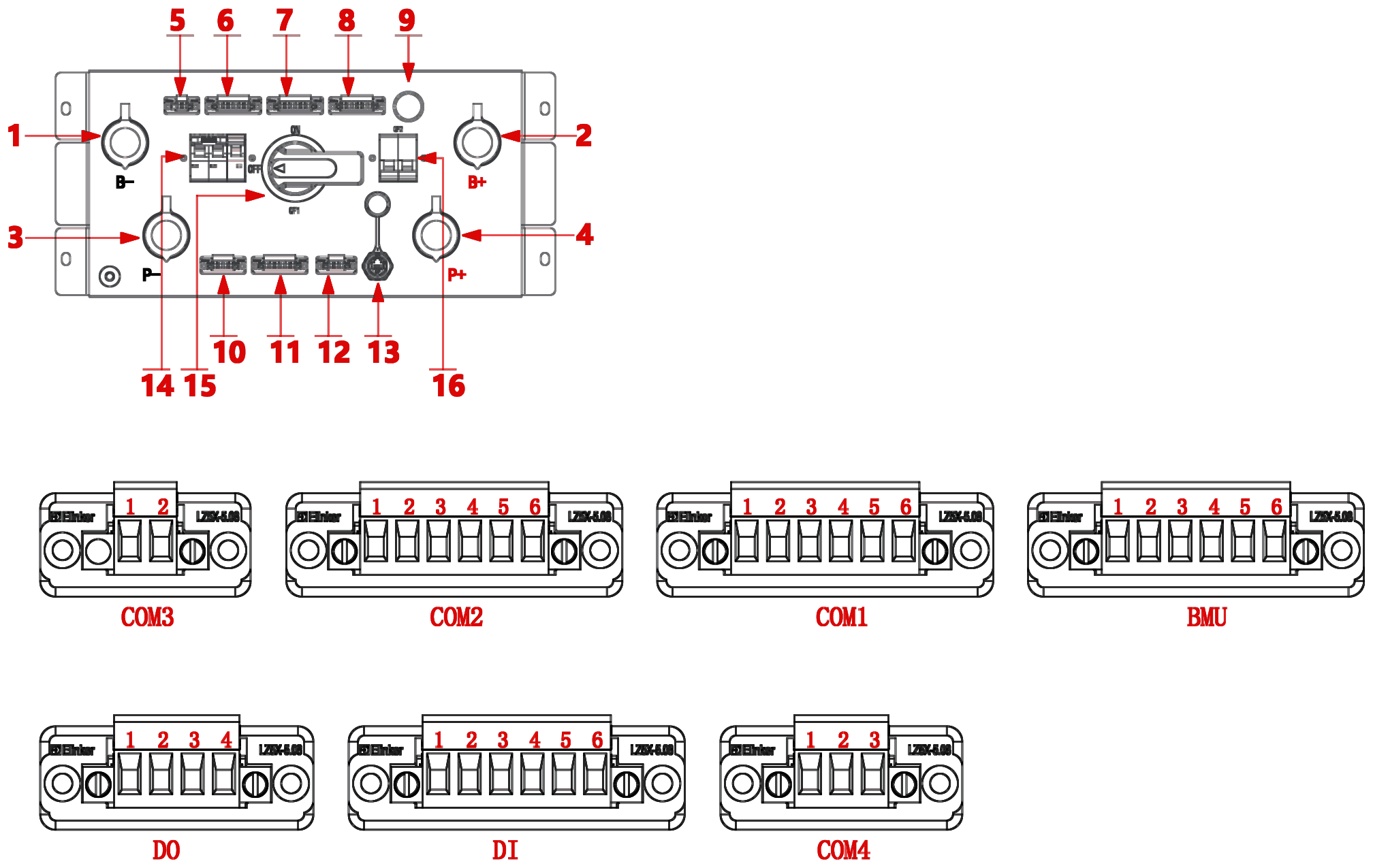
| No. | Label | Pin | Description |
|---|---|---|---|
| 1 | B− | B− | To the battery pack negative terminal |
| 2 | B+ | B+ | To the battery pack positive terminal |
| 3 | P− | P− | To the inverter negative terminal |
| 4 | P+ | P+ | To the inverter positive terminal |
| 5 | COM3 | 1: 24 V DC+ · 2: 24 V DC− | 24 V DC supply for the battery pack fans |
| 6 | COM2 | 1: RS485 A · 2: RS485 B | Spare |
| 6 | COM2 | 3: RS485 A · 4: RS485 B | Communication module (dongle) interface |
| 6 | COM2 | 5: RS485 A · 6: RS485 B | Air-conditioner RS485 interface |
| 7 | COM1 | 1: 24 V DC+ · 2: 24 V DC− | 24 V DC supply (BA) |
| 7 | COM1 | 3: CAN H · 4: CAN L | BMS debug CAN port |
| 7 | COM1 | 5: CAN H · 6: CAN L | Inverter communication CAN port |
| 8 | BMU | 1: 24 V DC+ · 2: 24 V DC− | 24 V DC BMU supply |
| 8 | BMU | 3: ADD SET · 4: — | BMU address setting |
| No. | Label | Pin | Description |
|---|---|---|---|
| 8 | BMU | 5: CAN H · 6: CAN L | BMU CAN interface |
| 9 | HR | — | High-voltage box fault indicator |
| 10 | DO | 1: NO1 · 2: COM1 | Cabinet running signal output (running indicator) |
| 10 | DO | 3: NO2 · 4: COM2 | Cabinet fault signal output (fault indicator) |
| 11 | DI | 1 | Signal input common |
| 11 | DI | 2 | SPD status input |
| 11 | DI | 3 | Fire status input |
| 11 | DI | 4 | Flood status input |
| 11 | DI | 5 | Door switch status input |
| 11 | DI | 6 | Emergency stop button status input |
| 12 | COM4 | 1: 220 V AC L · 2: N · 3: PE | AC supply for the BMS |
| 13 | LAN | — | BCU to BAMS communication |
| 14 | QF3 | — | Controller DC supply breaker |
| 15 | QF1 | — | Controller main switch |
| 16 | QF2 | — | Controller AC supply breaker |
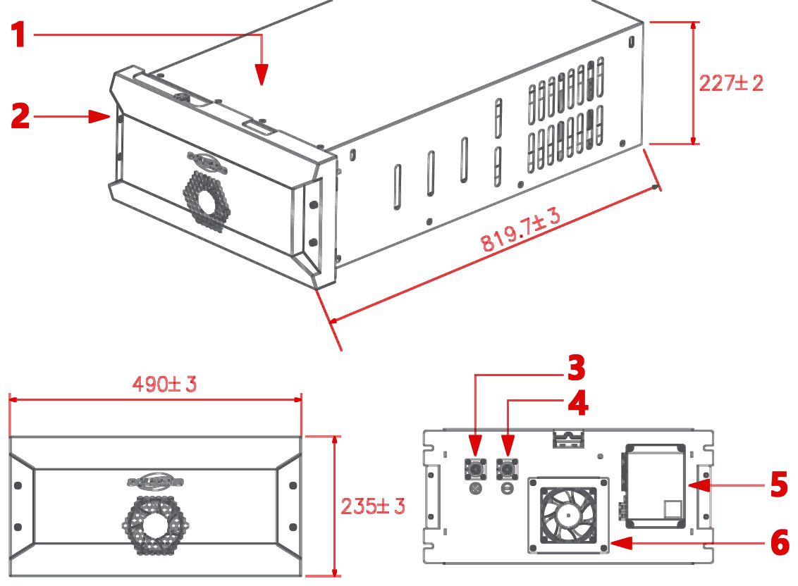
| No. | Name | No. | Name |
|---|---|---|---|
| 1 | Battery pack | 4 | Battery pack negative terminal |
| 2 | Front cover | 5 | BMU |
| 3 | Battery pack positive terminal | 6 | Fan |
| No. | Item | Specification | Remarks |
|---|---|---|---|
| 1 | Cell type | MB31 | |
| 2 | Nominal capacity | 314 Ah | Standard cell charge and discharge |
| 3 | Nominal voltage | 51.2 V | 3.2 V per cell |
| 4 | Nominal energy | 16.076 kWh | Standard cell charge and discharge |
| 5 | Standard charge power | 0.5P | |
| 6 | Standard discharge power | 0.5P | |
| 7 | Cell balancing | Passive | |
| 8 | Thermal management | Forced air cooling | |
| 9 | Operating temperature | Discharge −20 to 50 °C · Charge 1 to 50 °C | |
| 10 | Storage temperature | −20 to 45 °C | |
| 11 | Fire protection | Built-in aerosol module | |
| 12 | Operating humidity | 5–95% RH | |
| 13 | Storage conditions | Under 1 month: −30 to 55 °C, 90% RH max Over 3 months: −10 to 45 °C, 90% RH max Recommended: 10 to 30 °C, 85% RH max | |
| 14 | Ingress protection | IP20 | |
| 15 | Weight | 114 ± 5 kg | Including front cover |
| 16 | Dimensions (W × H × D) | 487 × 227 × 791.5 mm 490 × 235 × 819.7 mm | Excluding front cover Including front cover |
| 17 | Maximum altitude | 3000 m | Derate above 3000 m |
| 18 | Enclosure material | SGCC (galvanised steel) | |
| 19 | Front cover material | SPCC (cold-rolled steel) |
Keep the air-conditioner drain line clear. Water pooling in the cabinet from a blocked drain can damage the unit. Do not change the air-conditioner controller settings. Incorrect settings can stop it controlling the cabinet temperature and humidity, and damage the batteries.
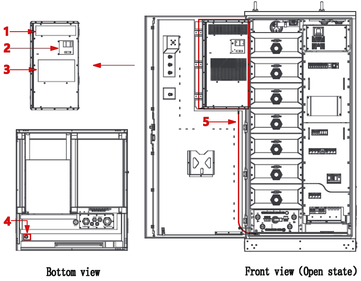
| No. | Name | Description |
|---|---|---|
| 1 | Air outlet | Cool air out |
| 2 | Controller | Reads temperature and humidity, and controls them to the set points |
| 3 | Return air inlet | Draws in warm air from the cabinet |
| 4 | Drain outlet | Condensate drain |
| 5 | Drain hose | Condensate drain |
Run the end of the drain hose out through the air-conditioner drain port. We recommend running it to a drain, so that water does not collect under the cabinet.
| Air conditioner | Specification |
|---|---|
| Rated supply | 230 V AC ± 10%, 50 ± 1 Hz |
| Rated power (cooling / heating) | 1.0 / 2.2 kW |
| Rated current (cooling / heating) | 4.6 / 10.2 A |
| Rated cooling capacity | 2.0 kW |
| Heating power | 2.0 kW |
| Maximum operating current | 11 A |
| Airflow, internal fan | 800 m³/h |
| Airflow, external fan | 900 m³/h |
| Temperature control range | 20 to 50 °C |
| Humidity control | Yes |
| Operating temperature | −40 to 50 °C |
| Refrigerant | R134a |
The door switch at the top right of the cabinet tells the high-voltage box when the door is open. Close the door when you finish work, to keep out moisture and small animals. The cabinet light switches on automatically when the door opens. Leave the light switch in its normal position. The light switches off 30 seconds after the door closes.
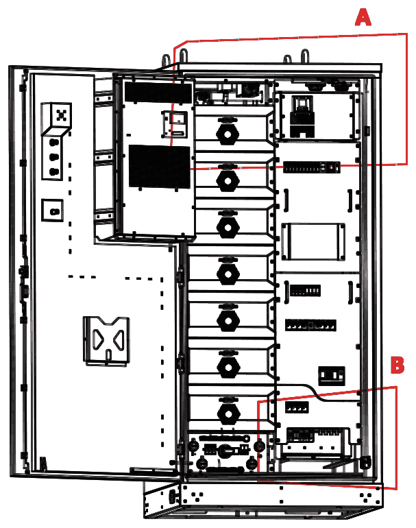
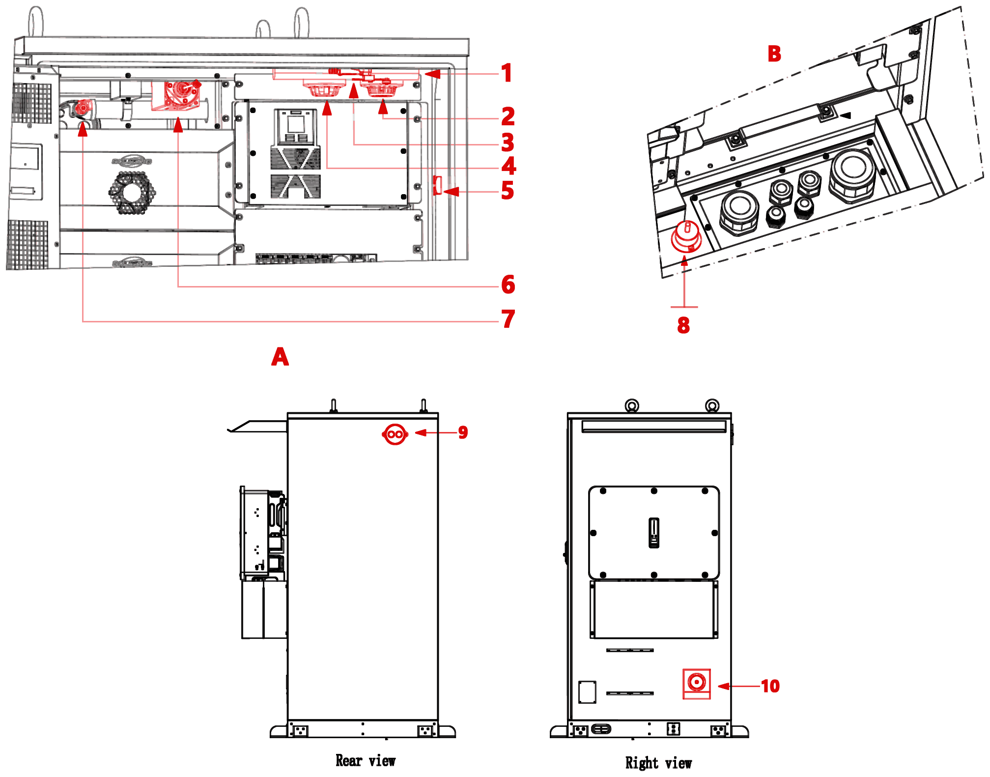
| No. | Name | Description |
|---|---|---|
| 1 | Automatic light | Switches on when the door opens and off 30 s after it closes |
| 2 | Temperature sensor | Measures the cabinet temperature and signals the fire-control system |
| 3 | Door switch | Monitors whether the cabinet door is open or closed |
| 4 | Smoke sensor | Measures smoke concentration and signals the fire-control system |
| 5 | Fire test terminal | Disconnect here before fire testing, so the aerosol extinguisher does not discharge |
| 6 | Aerosol fire module | Receives the fire alarm signal and activates the fire-protection system |
| 7 | Extinguisher nozzles | Discharge the extinguishing agent |
| 8 | Flood sensor | Detects water in the cabinet and signals the high-voltage box |
| 9 | Explosion-relief vent | Releases gas pressure |
| 10 | Fire-water inlet | Connection for an external fire-water supply |
Battery pack protection. Each battery pack has its own aerosol extinguishing module. It discharges when a fire triggers its thermal fuse line (170 °C).
Cabinet protection. As standard, the cabinet also has a separate aerosol fire module with smoke and temperature detectors. The system automatically detects a fire, activates the extinguishing module and discharges the agent, reports the discharge to the BMS through a dry contact, and disconnects the main power circuit.
The All-In-One inverter is a Solinteg M2HT 25–50 kW hybrid inverter. It is packed separately from the cabinet and mounted on the side of the cabinet during installation (section 4.2.3). The illustration below is for reference only. See the inverter manual for details.
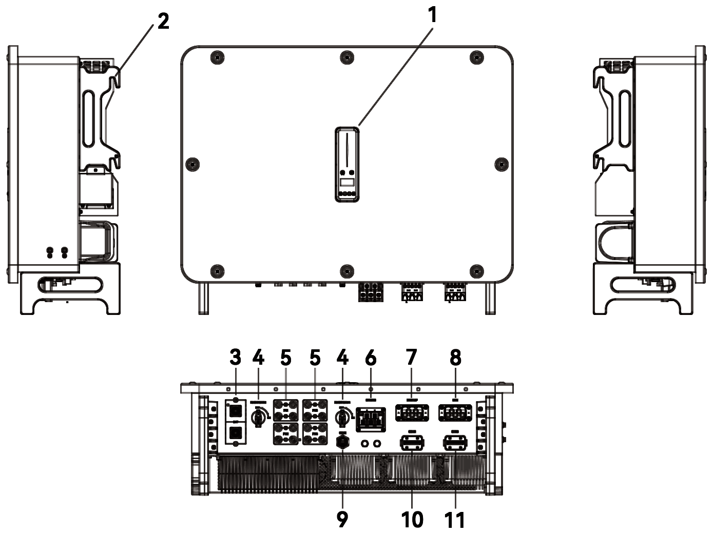
| No. | Name | Description |
|---|---|---|
| 1 | Indicators, OLED display and button | Show the inverter's operating information and status |
| 2 | Hanger | Hangs the inverter on its mounting bracket |
| 3 | Battery input terminals | Battery connectors |
| 4 | DC switch | Safely isolates the DC circuit |
| 5 | DC input terminals | PV connectors |
| 6 | On-grid output terminal | On-grid output cable connection |
| 7 | Back-up output terminal | Back-up output cable connection |
| 8 | Generator input terminal | Diesel generator AC cable connection |
| No. | Name | Description |
|---|---|---|
| 9 | COM1 port | Communication module (dongle) |
| 10–11 | COM2 and COM3 ports | Multi-function communication connectors |
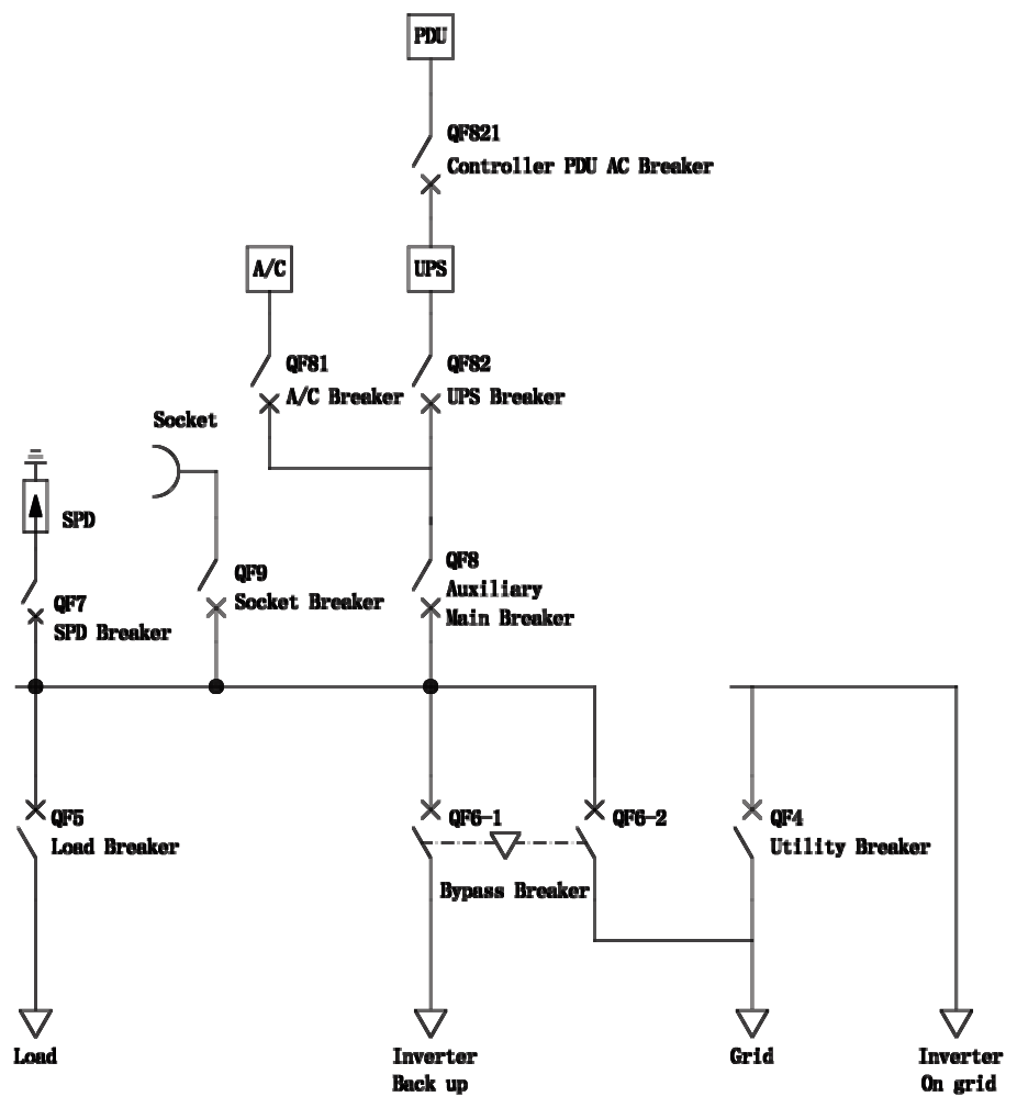
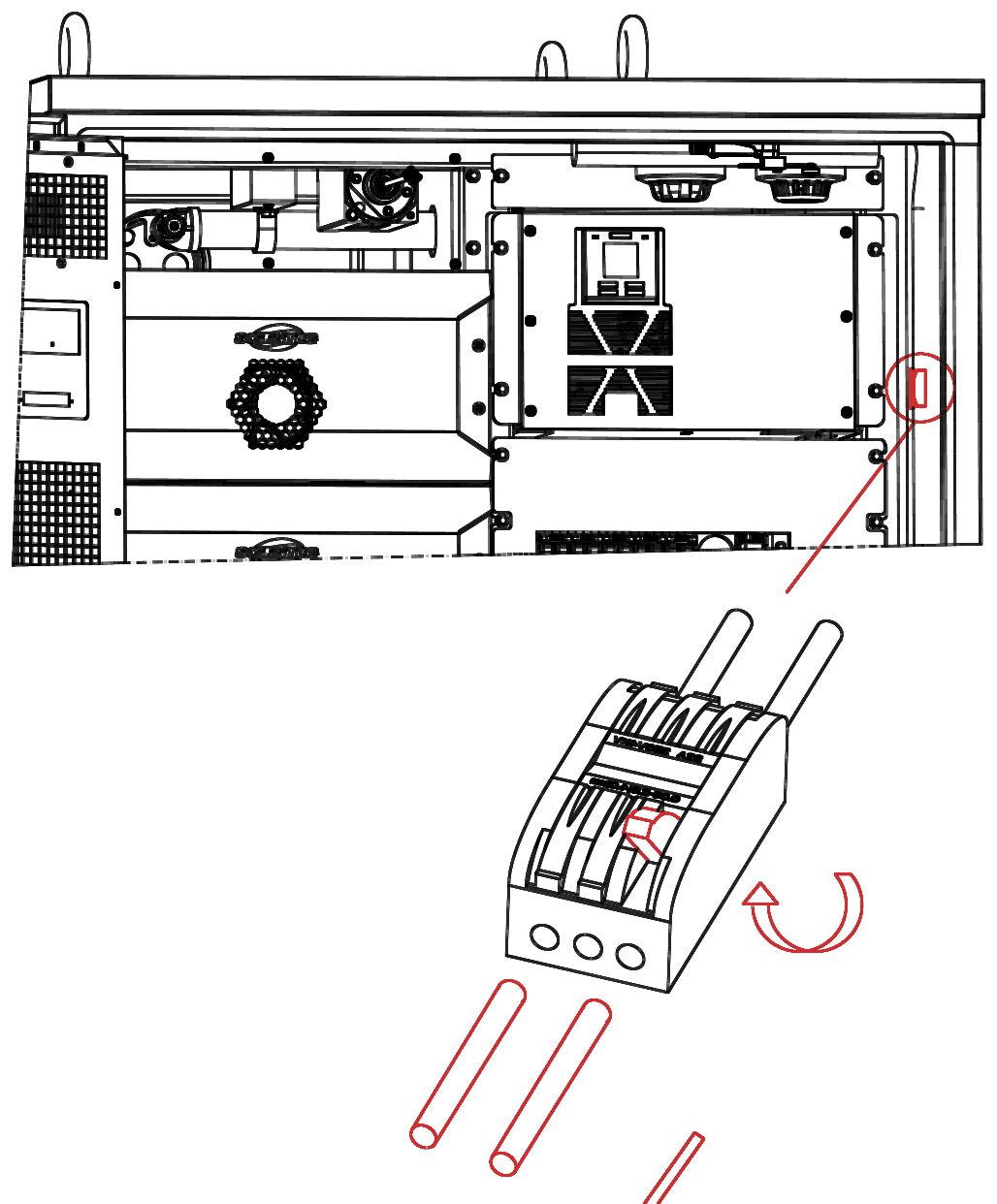
In normal operation, leave the bypass switch in the left-hand (normal) position, as shown below.
If the grid is healthy but the cabinet has a fault, switch to bypass supply:
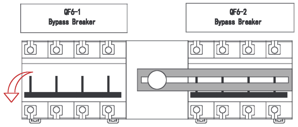
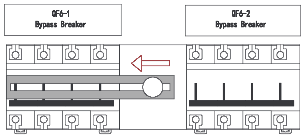
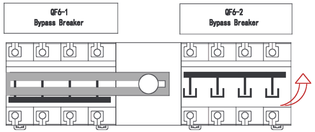
In bypass, the cabinet cannot supply the loads and the inverter cannot start. The auxiliary circuits (high-voltage box, air conditioner, door switch and sockets) keep running.
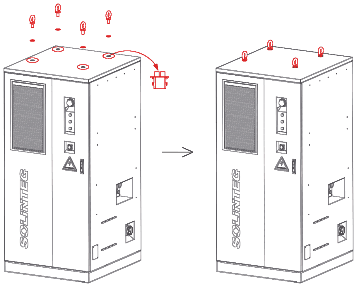
Inspect the outer packaging before you accept delivery. Unpack only if it is intact. If the packaging is damaged, contact your supplier immediately. The parts box is inside the cabinet. Open the cabinet door to remove it after unpacking. After unpacking, remove the decorative panels from around the cabinet and refit them as described in section 4.2.
You will need two adjustable spanners, a claw hammer, a flat-blade screwdriver, pliers, a ladder at least 1.5 m high, gloves and other PPE. The cabinet is more than 2 m tall, so use the controls required for working at height.
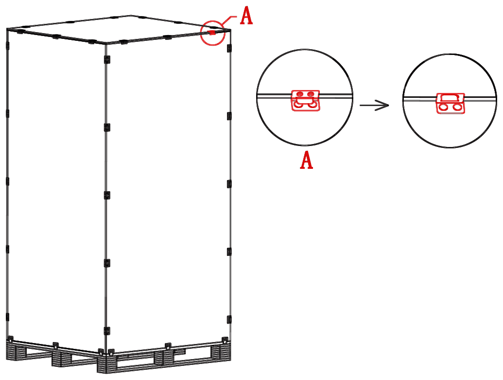
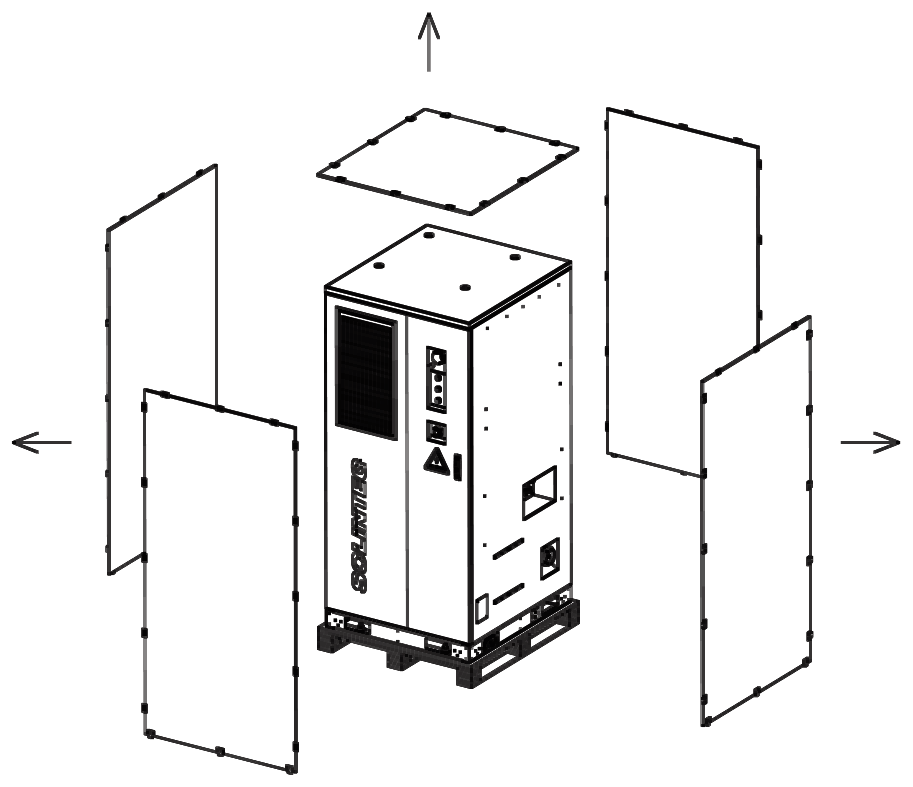
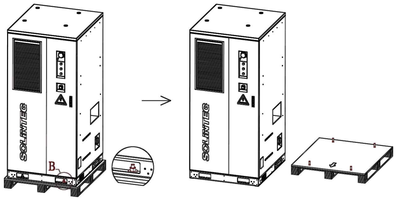
Protect the equipment from water during transport, avoid impacts, and never transport it upside down. Damage can lead to fire or explosion. Before transport, check the packaging for damage, odour, leaks and other abnormalities. Never transport damaged goods: they may cause fire or explosion.
Follow the warning labels on the packaging and the cabinet, and all transport requirements. Secure the cabinet so it cannot tip during transport and handling. Keep the tilt angle at 10° or less. Choose a transport method that suits the equipment and protect it during transport. The cabinet contains lithium-ion batteries (Class 9 dangerous goods). The carrier must be licensed to carry dangerous goods and must comply with the regulations that apply. In Australia, this is the Australian Dangerous Goods Code.
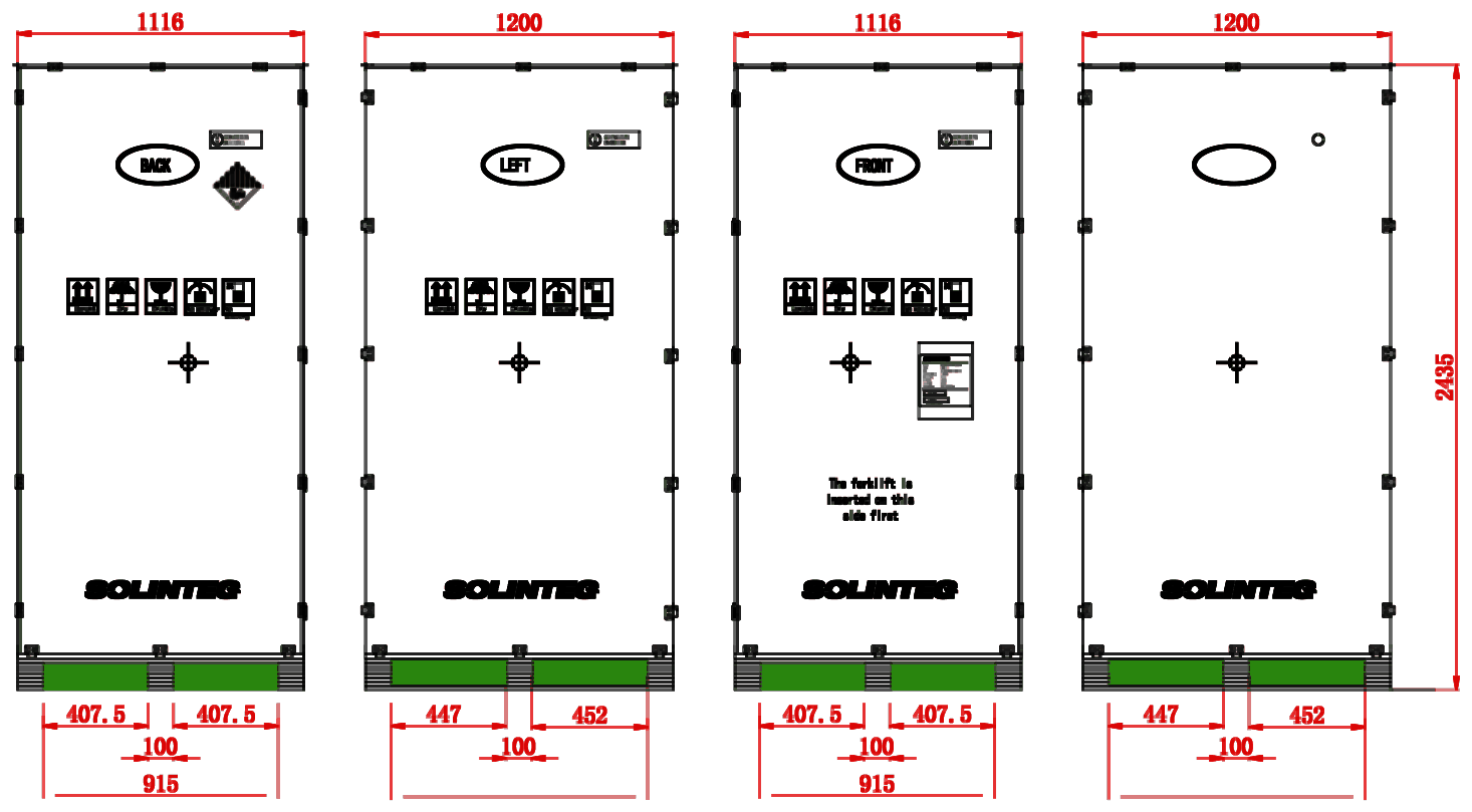
Choose the storage conditions to suit the storage time:
| Storage time | Temperature | Relative humidity |
|---|---|---|
| Up to 3 months | −20 to 45 °C | 90% max |
| More than 3 months | −10 to 45 °C | 90% max |
| Recommended | 10 to 30 °C | 85% max |
The batteries are installed in the cabinet, so the battery storage requirements also apply.
Store batteries indoors, in an area that is out of direct sun and rain, dry and ventilated, away from heat and ignition sources, free of radiation, chemically safe, free of dust and conductive metal dust, and equipped with fire-protection equipment. Store batteries as instructed by the warning labels on the packaging. Do not store them with other electronic equipment, chemicals or anything else that may cause interference or a hazard. Limit stacking height so the lower layers are not crushed or deformed.
Long-term storage of batteries is not recommended. If it cannot be avoided, recharge the batteries regularly to prevent damage. A battery stored for more than six months must be inspected and tested by a qualified person before use.
| Item | Name | Specification | Qty |
|---|---|---|---|
| 1 | Battery cabinet | Solinteg E2BR-S64–112K-C | 1 set |
| 1.1 | Cabinet door key | — | 2 |
| 1.2 | Decorative panel | — | 4 |
| 1.3 | Power cable to inverter on-grid port | 3L + N + PE | 1 |
| 1.4 | Power cable to inverter back-up port | 3L + N + PE | 1 |
| 1.5 | Battery cable | BAT+ | 1 |
| 1.6 | Battery cable | BAT− | 1 |
| 2 | Parts box | — | 1 set |
| 2.1 | Rain shelter (with seal) | 1000 × 415 × 80 mm | 1 |
| 2.2 | Cable cover 01 | 830 × 150 × 400 mm | 1 |
| 2.3 | Cable cover 02 | 398.5 × 166.7 × 53.5 mm | 2 |
| 2.4 | Mounting foot | 100 × 120 × 80 mm | 4 |
| 2.5 | Lifting eye (with rubber washer) | M24 | 4 |
| 2.6 | Hex bolt | M6 × 16 | 11 |
| 2.7 | Hex bolt | M8 × 16 | 10 |
| 2.8 | Hex bolt | M8 × 25 | 12 |
| 2.9 | Countersunk screw | M5 × 10 | 24 |
| 2.10 | Expansion anchor | M20 × 150 | 4 |
| 2.11 | Communication module | — | 1 |
| Item | Name | Specification | Qty |
|---|---|---|---|
| 2.12 | Gland sealing ring | M42-26 | 1 |
| 2.13 | Lug, grid cable | SC50-8 | 4 |
| 2.14 | Lug, PE | SC16-8 | 2 |
| 2.15 | Lug, load cable | C45-25 | 4 |
| 2.16 | Battery communication cable | — | 1 |
| 2.17 | Inverter emergency stop cable | — | 1 |
| 3 | Document pocket | — | 1 set |
| 3.1 | User manual | — | 1 |
| 3.2 | Single-line diagram | — | 1 |
If the lugs in the parts box do not suit your cables, supply suitable lugs.
Keep the cabinet door keys secure. Only authorised people may have access to them.
Choose a site that meets the product requirements, local fire codes, and the laws and regulations that apply.
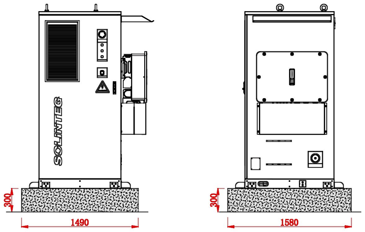
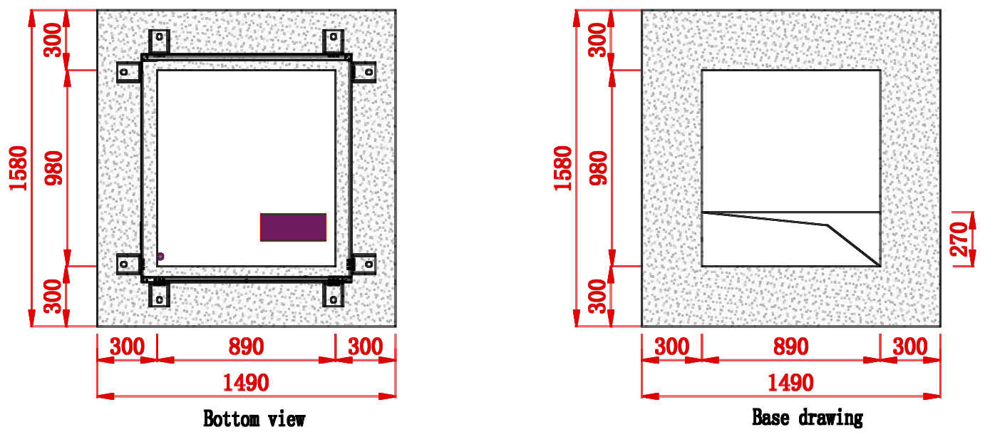
The cabinet weighs up to about 1440 kg (S112) and the inverter 89 kg. Design the foundation for at least 2 t, the local seismic code and the ground conditions, so that it can carry the cabinet and the people working on it. Build the foundation from concrete, solid brick, steel or a similar material. Compact and level the base: the level tolerance is 3 mm and the slope must not exceed 5°. The foundation must not sag or tilt.
Provide cable trenches or conduit entries in the foundation, and avoid buried services when you build it.
The drawings below are for reference only. Design and build the foundation to suit the site and local requirements.
| Minimum distance from | Distance |
|---|---|
| The coast | More than 2000 m |
| Heavy pollution sources: smelters, coal mines, thermal power stations and similar | More than 1500 m |
| Medium pollution sources: chemical, rubber and electroplating plants and similar | More than 1000 m |
| Light pollution sources: food processing, tanneries, boilers, abattoirs, landfills, sewage treatment plants and similar | More than 500 m |
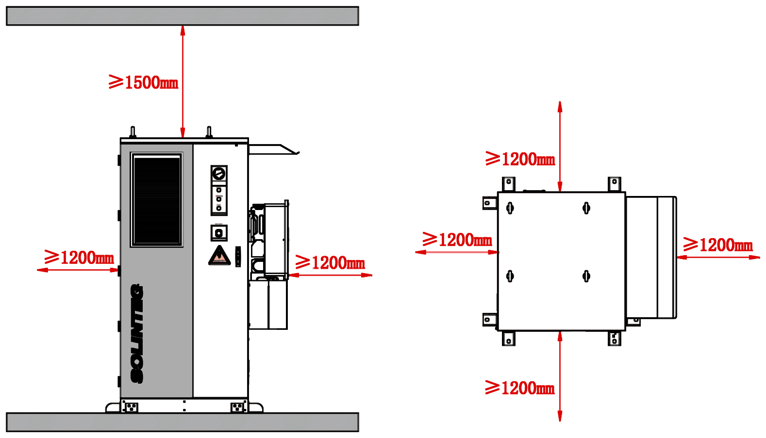
Keep the clearances shown below around the cabinet.
You need at least the tools below. Use other tools as the site requires. All tools must comply with local requirements.
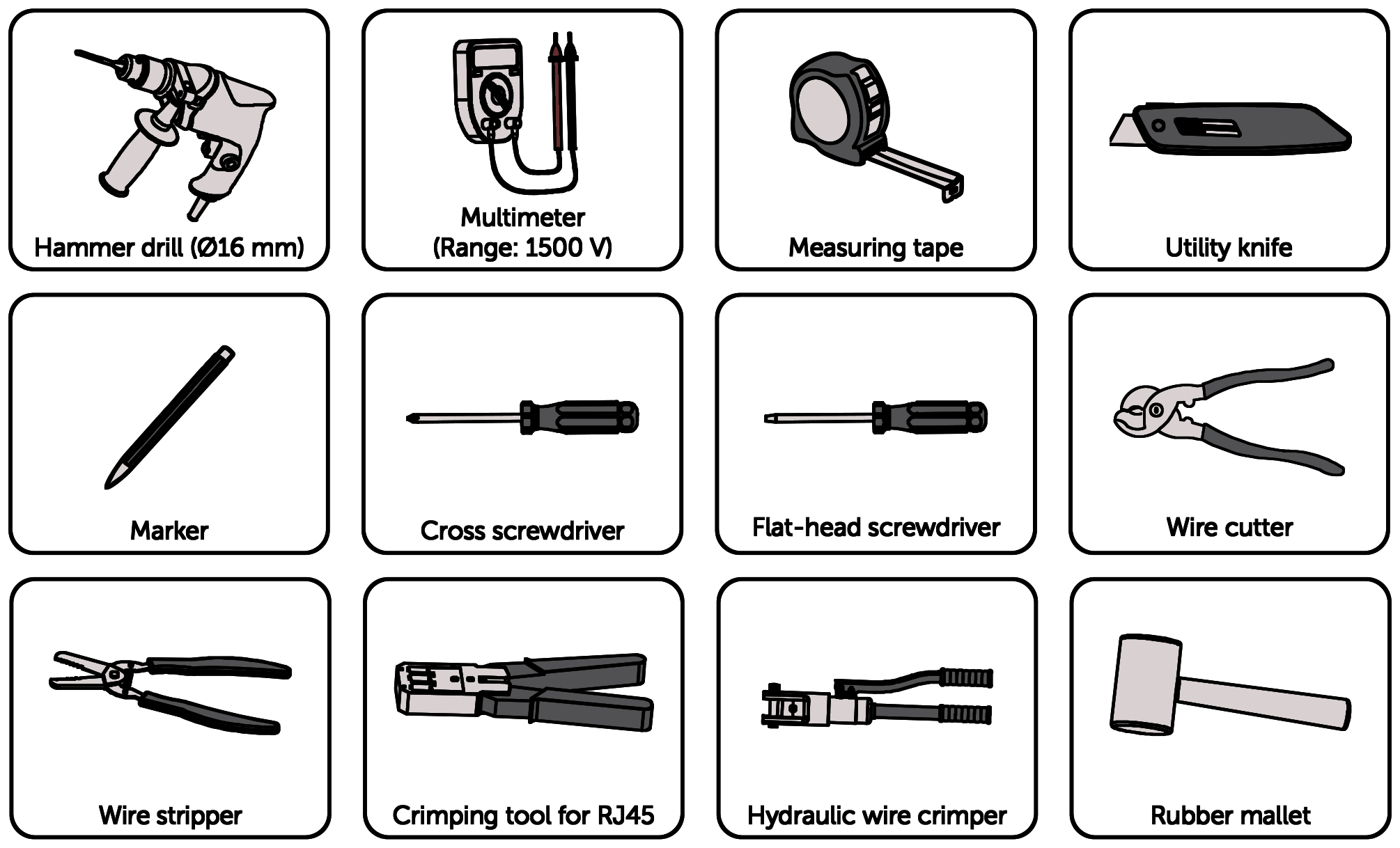
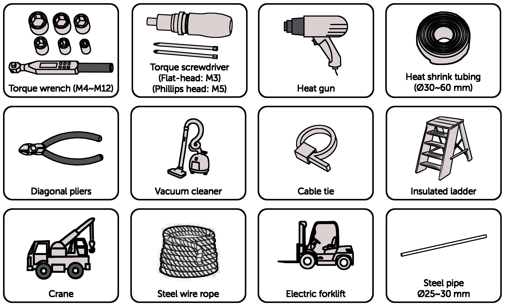
Take the mounting hardware out of the cabinet and check it against the packing list before you start, so you are not held up by missing parts.
Do not install, wire or operate the equipment outdoors in lightning, rain, snow or other severe weather. Before drilling, digging or other construction work, locate and avoid buried pipes and cables. Wear the PPE required by regulations. Cover the equipment, and the components inside the cabinet, during installation so that debris cannot get in. Clean the equipment when installation is complete.
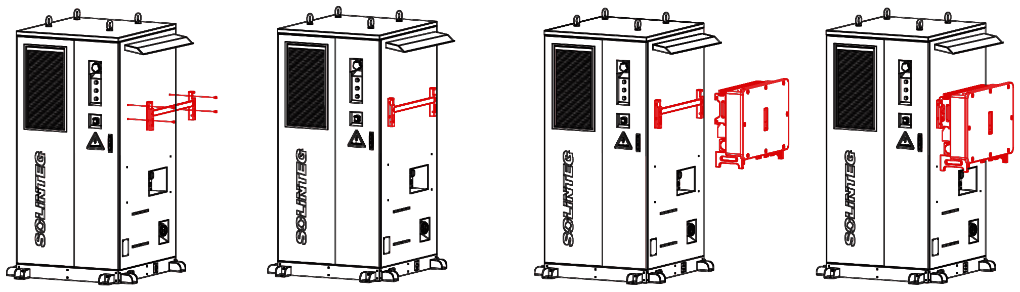
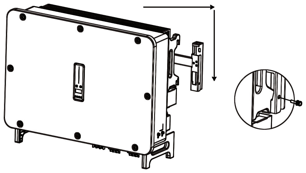
Read this manual before you start, so you understand all the installation requirements. Make sure the mechanical installation is complete and no parts or tools have been left in the cabinet. Check the seals on the cable entries before you start. Leave the waterproof plugs in unused cable entries. When installation is complete, seal the cable entries as local requirements specify.
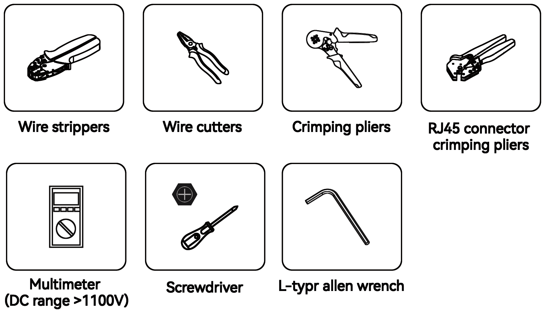
Wiring tools: wire strippers, side cutters, crimping tool, RJ45 crimping tool, multimeter (DC range above 1100 V), screwdrivers and hex keys.
Supply the following materials, selected to the recommended specifications and the site conditions.
| No. | Item | Recommended specification | Purpose |
|---|---|---|---|
| 1 | Grid cable | 4 × 35 mm² + 1 × 16 mm², or 4 × 50 mm² + 1 × 16 mm² | Cabinet to the site switchboard |
| 2 | Load cable | 4 × 25 mm² + 1 × 16 mm², or 4 × 35 mm² + 1 × 16 mm² | Cabinet to the site loads |
| 3 | Earth cable | 50 mm² green/yellow PE cable | Use a PE cable or an earthing flat bar, to suit the site |
| 4 | PE lug | SC50-8 | |
| 5 | Earthing flat bar | Hot-dip galvanised, 40 × 4 mm | |
| 6 | Cable tray or duct | To suit the site | Cable routing |
| 7 | Sealing material | To suit the site | Sealing cable entries |
| Cable | Recommended specification | Cable outside diameter |
|---|---|---|
| Grid cable | 4 × 35 mm² + 1 × 16 mm², or 4 × 50 mm² + 1 × 16 mm² | 37–44 mm |
| Load cable | 4 × 25 mm² + 1 × 16 mm², or 4 × 35 mm² + 1 × 16 mm² | 22–32 mm |
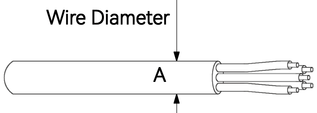
If the cable is smaller than the recommended diameter, seal it with the gland sealing ring or the fire-stopping putty from the parts box.
Connect the cabinet earth first, as soon as the cabinet is installed. When removing the cabinet, disconnect the earth last. A faulty earth is a danger to people and equipment. Keep the cabinet earth in good condition during commissioning and operation.
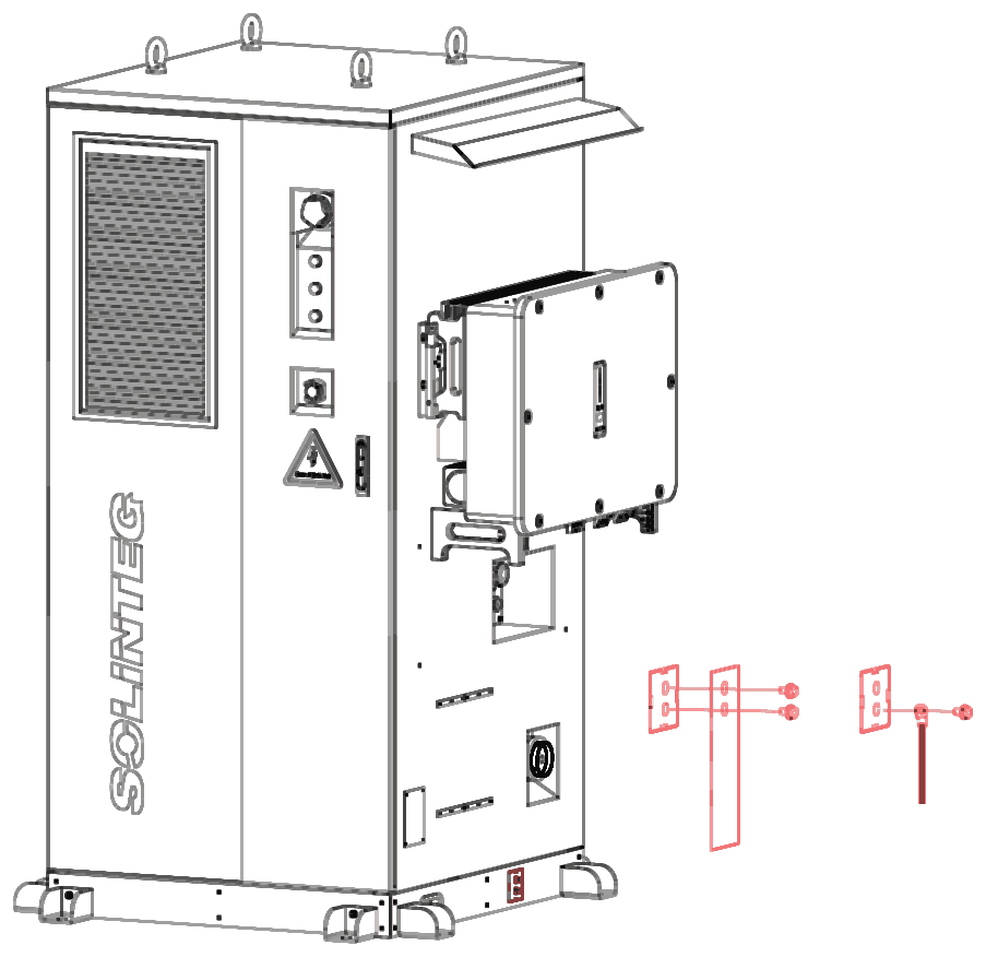
Make sure every power switch is off before you connect any cable, to avoid injury and short circuits. Make sure the cabinet earth is reliably connected before you connect any cable. Failure to do so can cause injury or death. Secure every cable terminal so it cannot loosen over time. A loose terminal can damage the equipment.
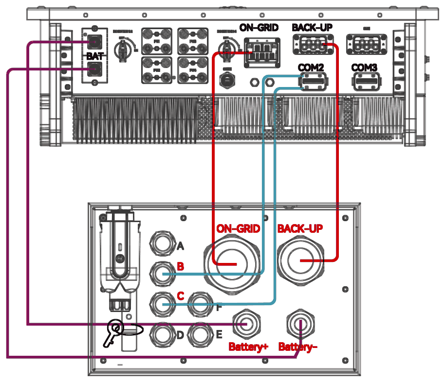
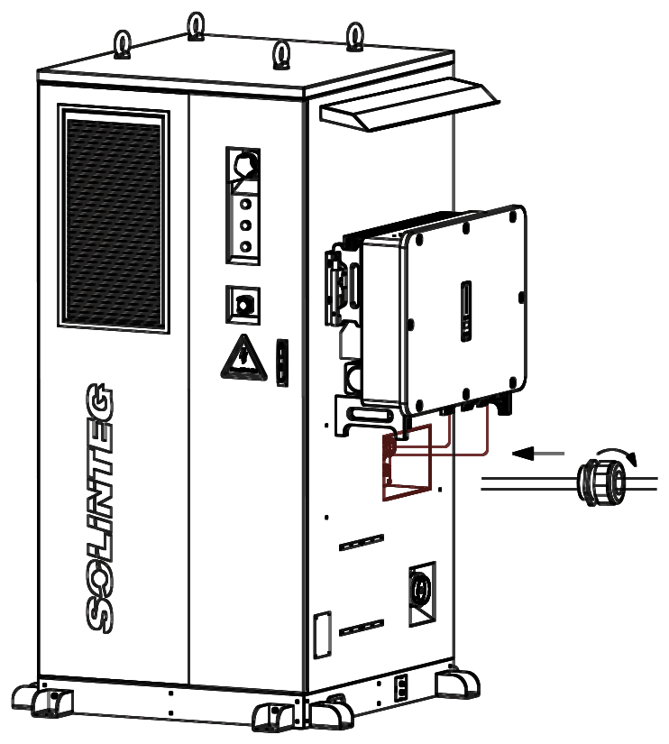
The cables between the cabinet and the inverter are supplied, with one end already connected inside the cabinet. After unpacking, check the cables for damage, then connect the other ends to the inverter as described below.
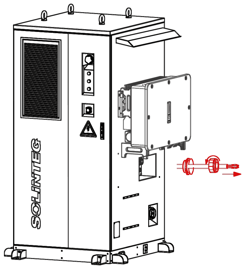
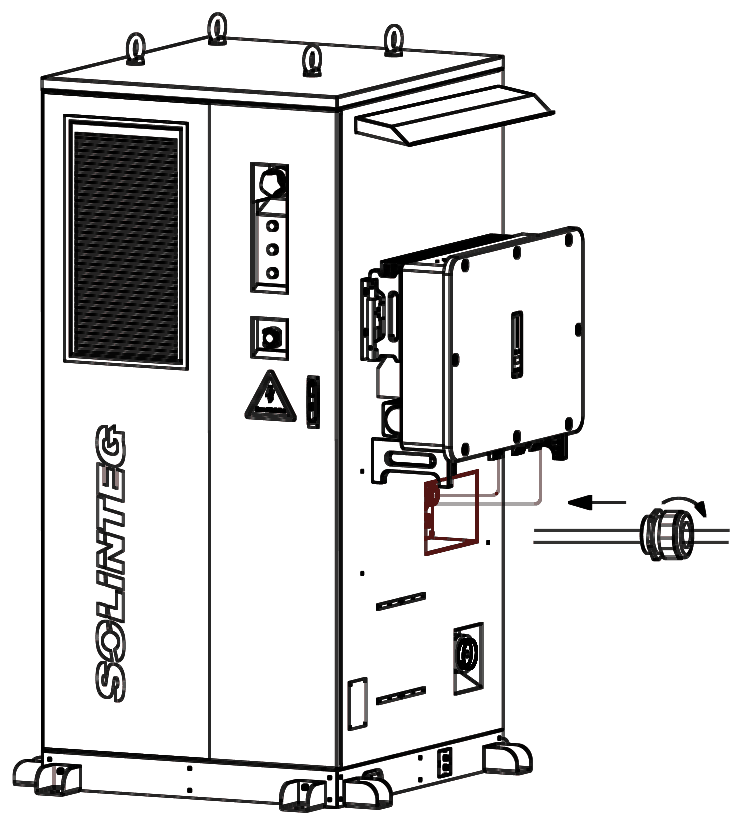
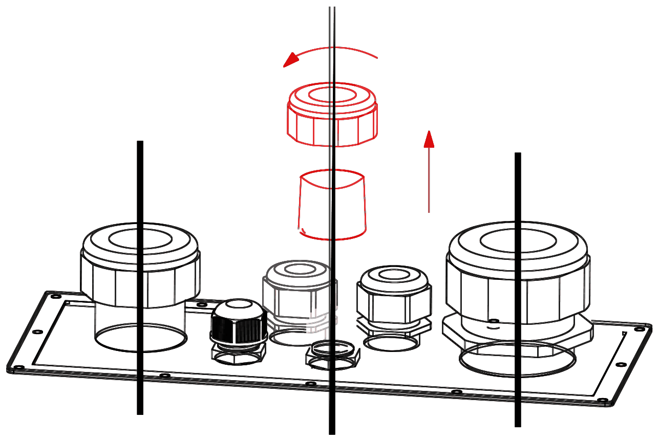
Connect the cables as shown in the diagram below and as the inverter manual requires. When all the wiring is done, tighten the gland compression nuts on the side cable panel.
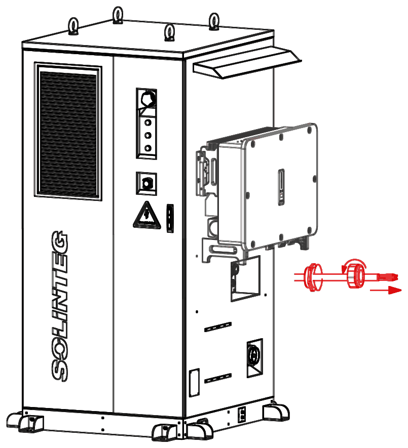
Loosen the compression nuts of the glands on the side cable panel, as shown below. Pull the inverter on-grid and back-up cables out far enough to reach the inverter terminals.
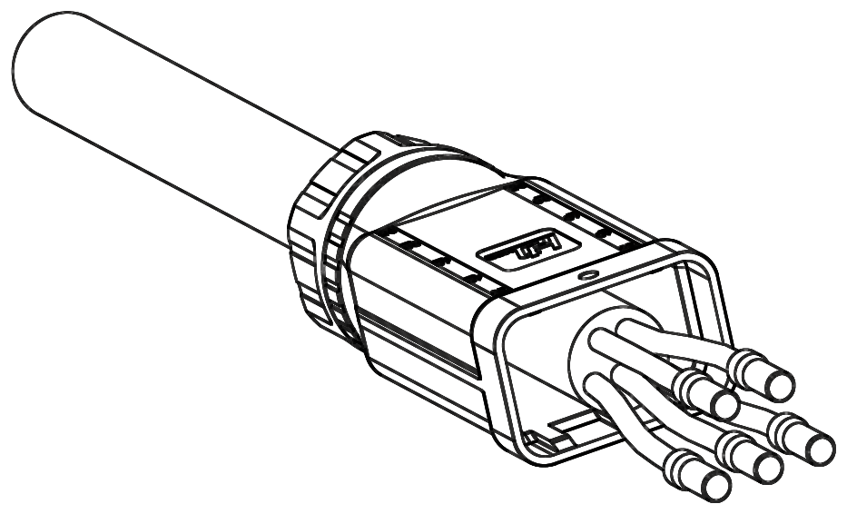
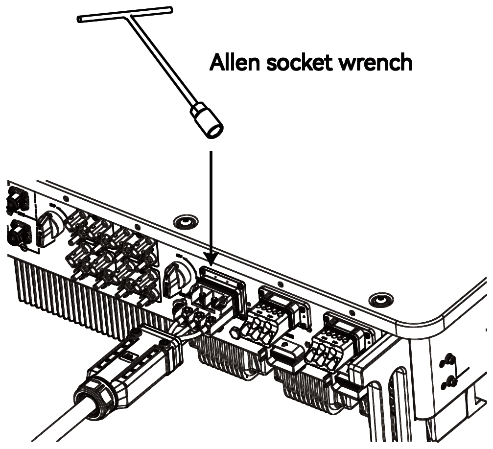
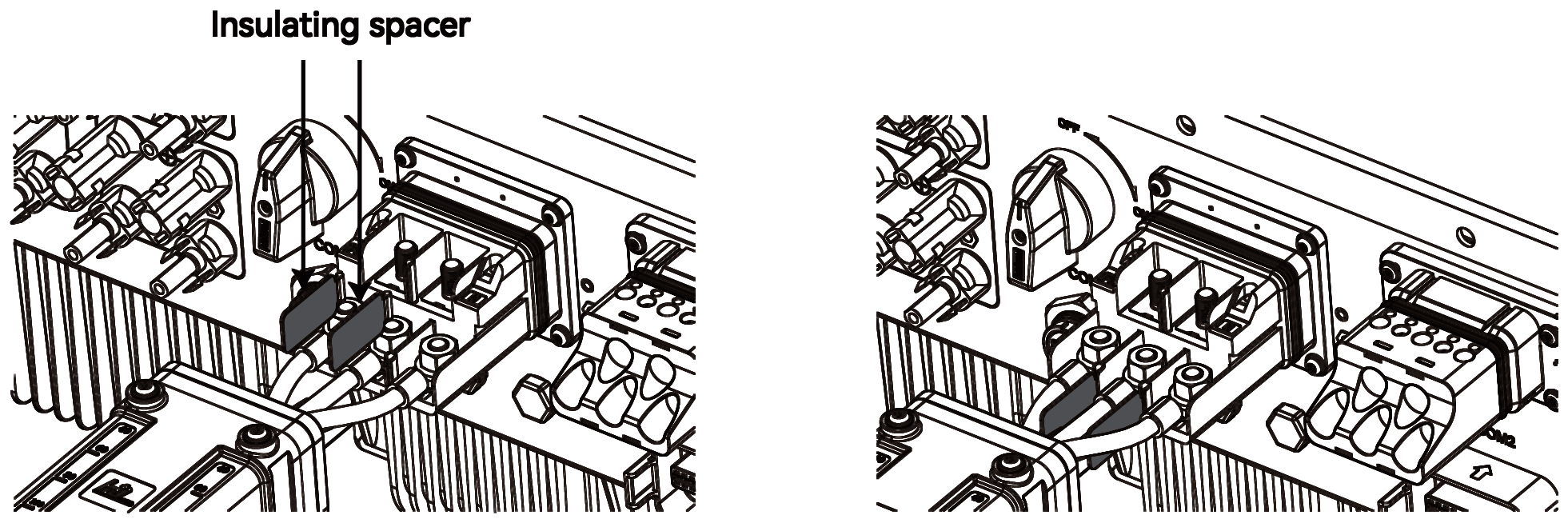
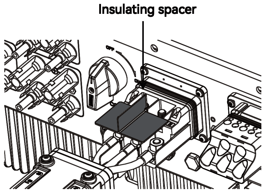
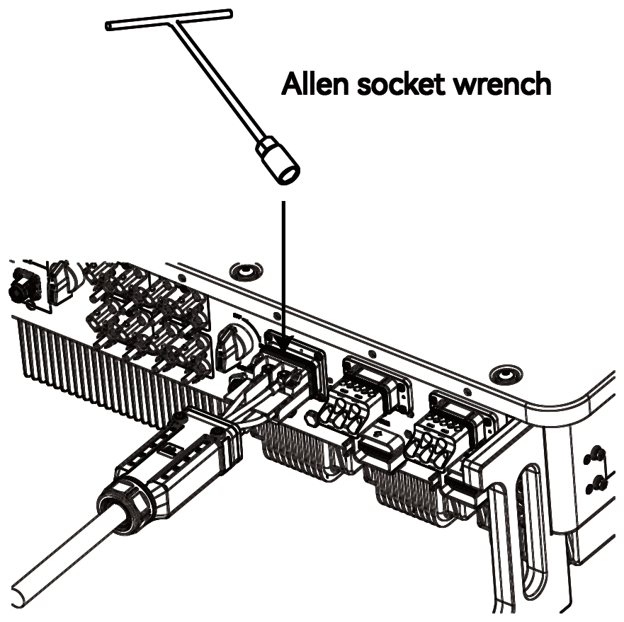
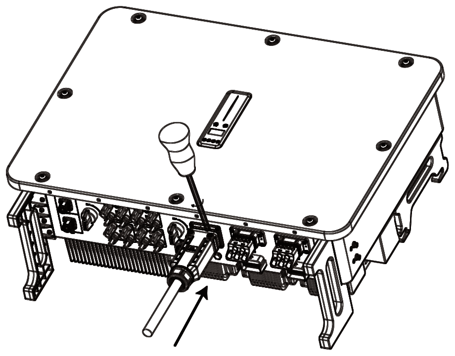
Do not confuse the back-up connector with the generator connector.
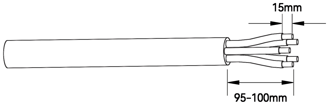
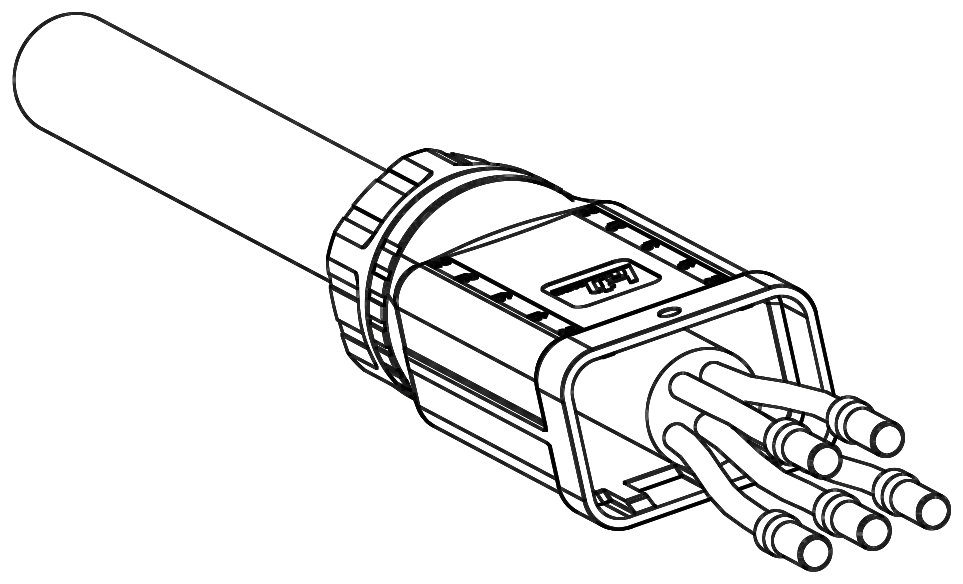
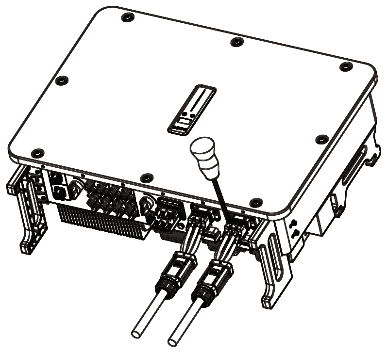
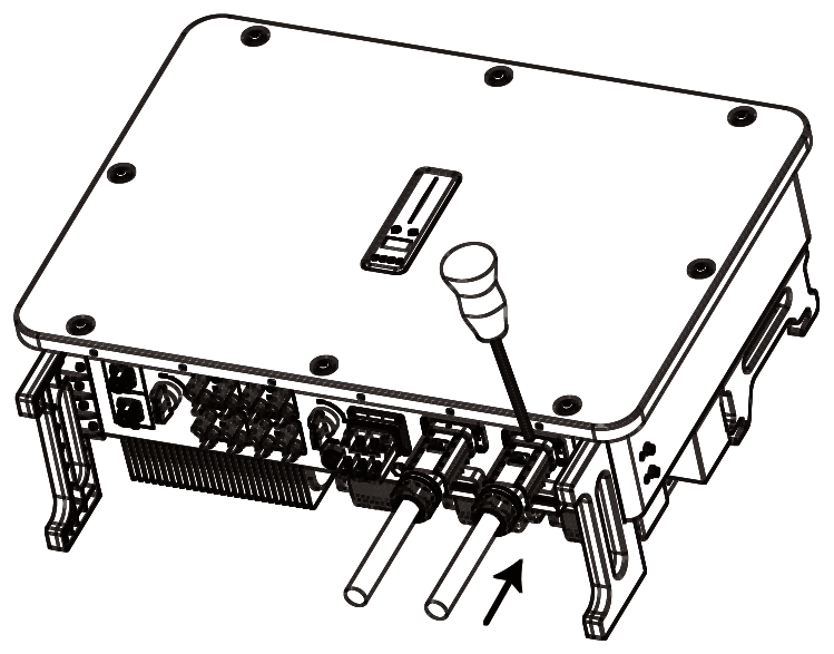
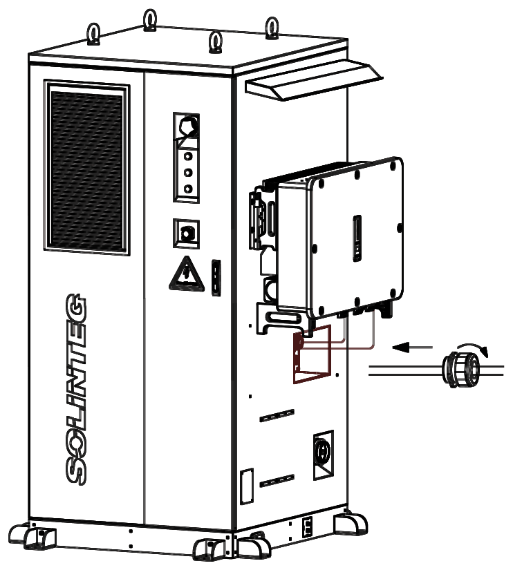
Before connecting the battery, open the grid-side AC breaker and the battery-side breaker, and turn the inverter DC switch to OFF.
Before connecting to the inverter, measure the battery terminal voltage with a multimeter. It must not exceed 840 V. Before connecting the battery terminals, check that the cable polarity is correct.
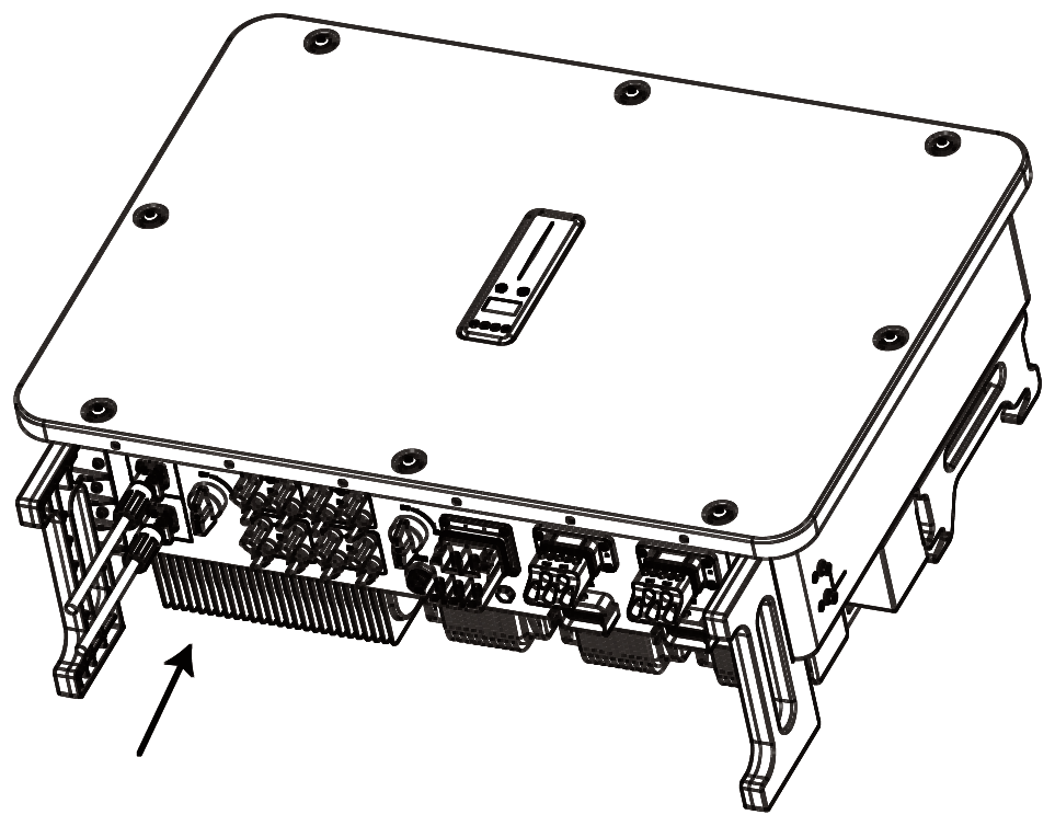
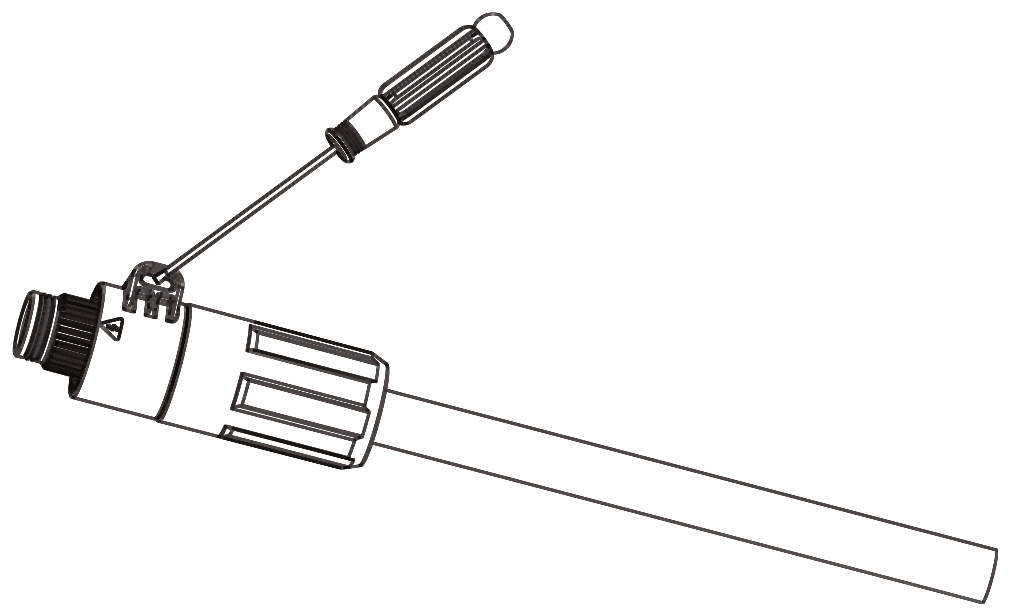
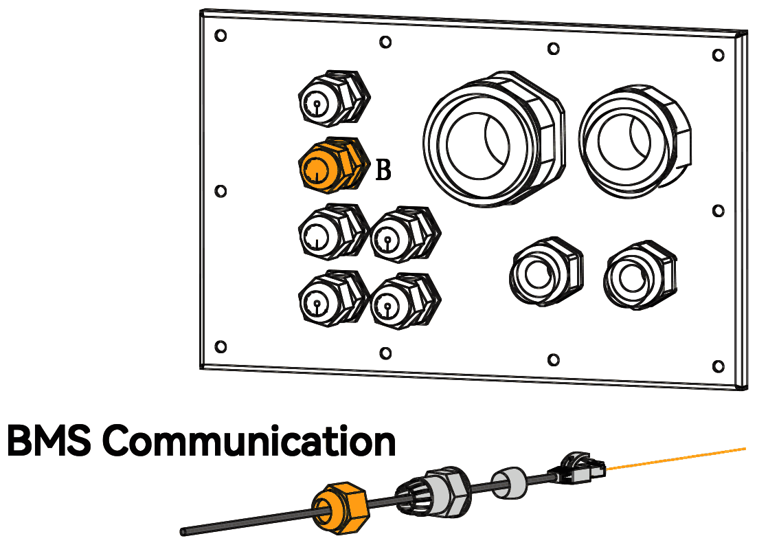
Do not earth an unused communication cable or connect it to other equipment.
Use the inverter's BMS 1 port. The BMS 2 port is not used. All the inverter COM3 connections are RJ45.
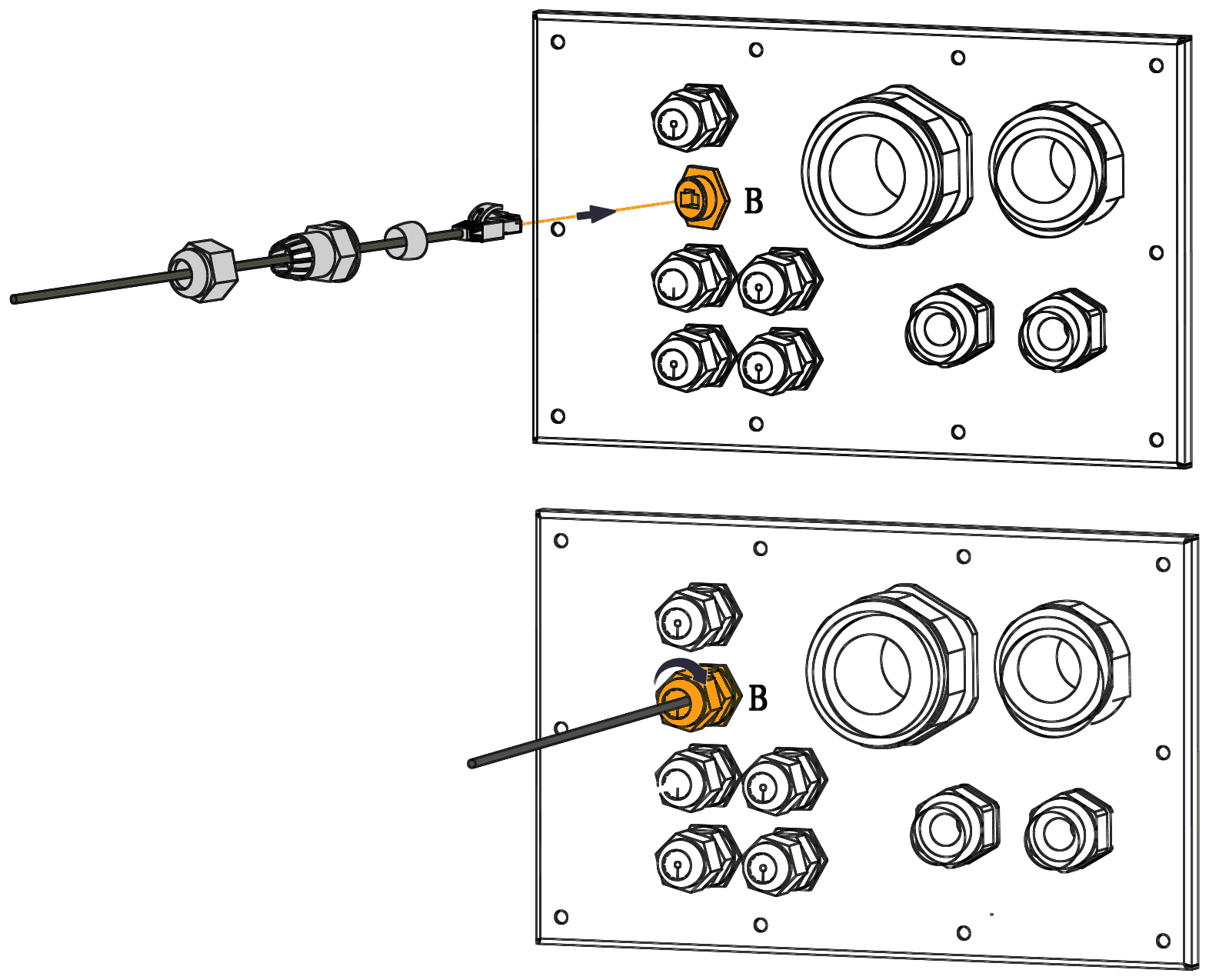
| Pin | Colour | BMS 1 signal |
|---|---|---|
| 1 | White/orange | RS485_A3 |
| 2 | Orange | RS485_B3 |
| 3 | White/green | — |
| 4 | Blue | CANH_B1 |
| 5 | White/blue | CANL_B1 |
| 6 | Green | — |
| 7 | White/brown | CANL_Debug |
| 8 | Brown | CANH_Debug |
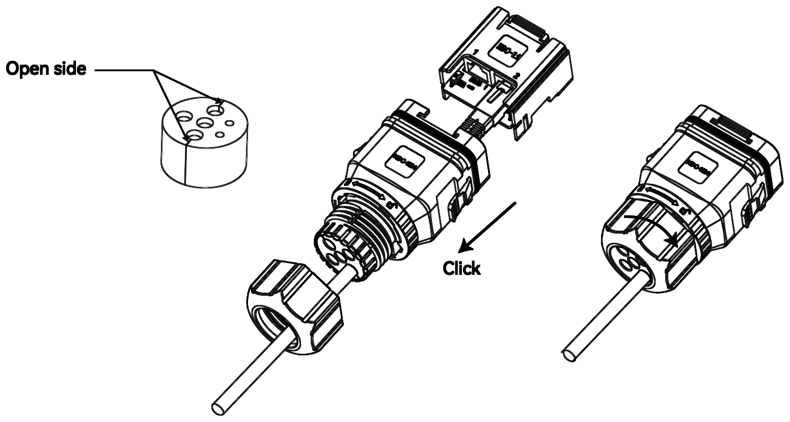
The inverter emergency stop uses the following pins.
| Pin | Colour | Signal |
|---|---|---|
| 1 | White/orange | Stop+ |
| 2 | Orange | Stop+ |
| 3 | White/green | Stop− |
| 4 | Blue | Stop− |
| 5 | White/blue | — |
| 6 | Green | — |
| 7 | White/brown | — |
| 8 | Brown | — |
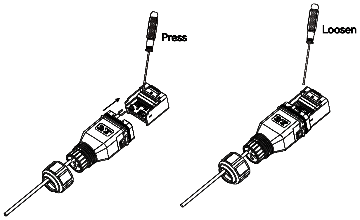
The inverter COM2 connector has push-in (screwless) terminals and an RJ45 socket. The steps below are for the push-in terminals.
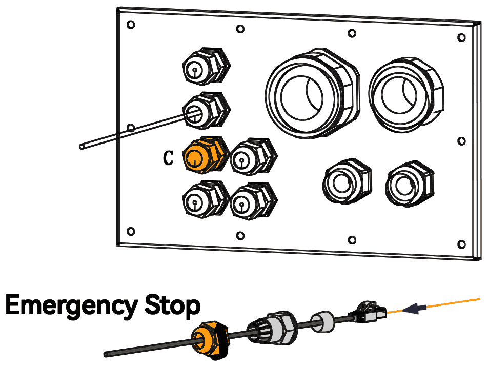
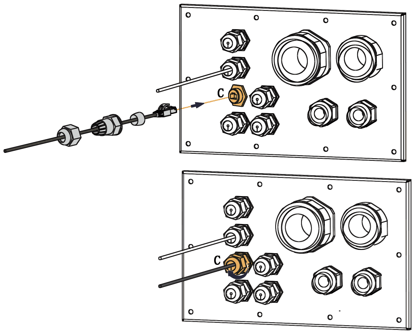
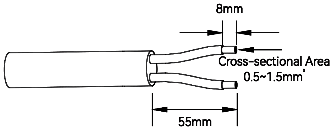
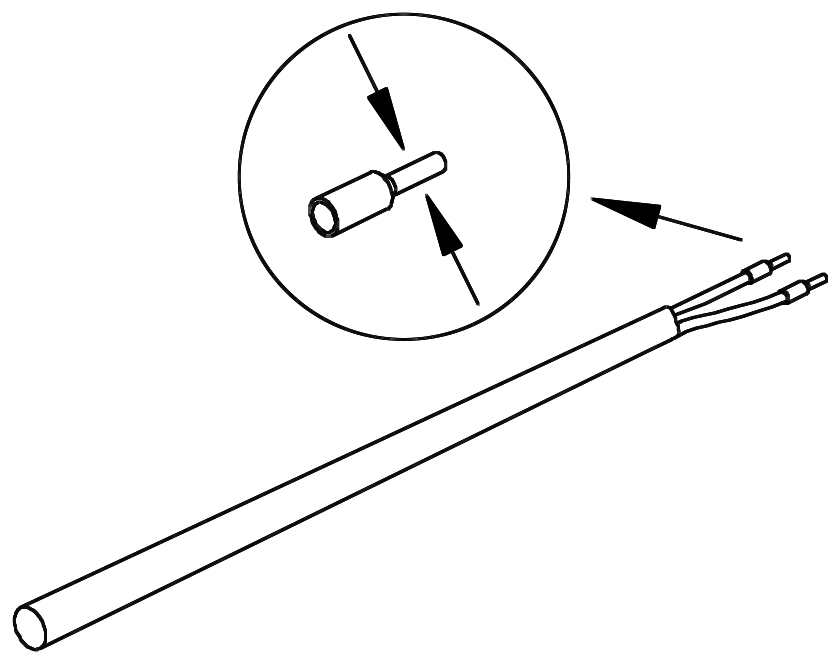
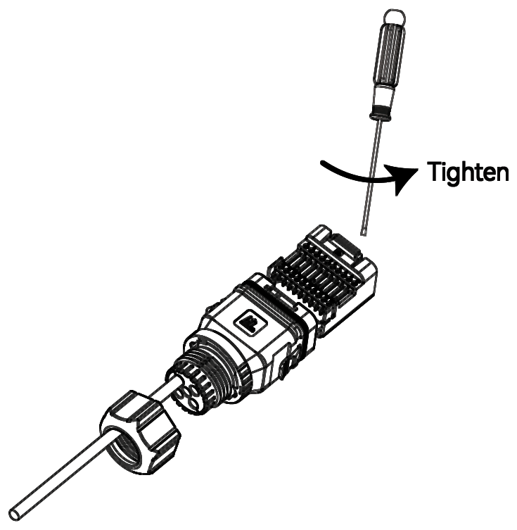
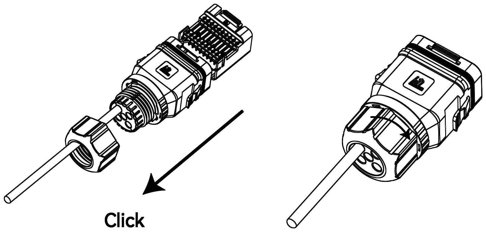
Choose the DC cable to suit the site. The recommended specification is:
| Cable | Outside diameter | Conductor size |
|---|---|---|
| DC (PV) cable | 5.9–8.8 mm | 4 mm² (12 AWG) or 6 mm² (10 AWG) |
For the PV wiring itself, follow the inverter manual.
We recommend fitting the cable cover after all the cables are connected and the system is commissioned.
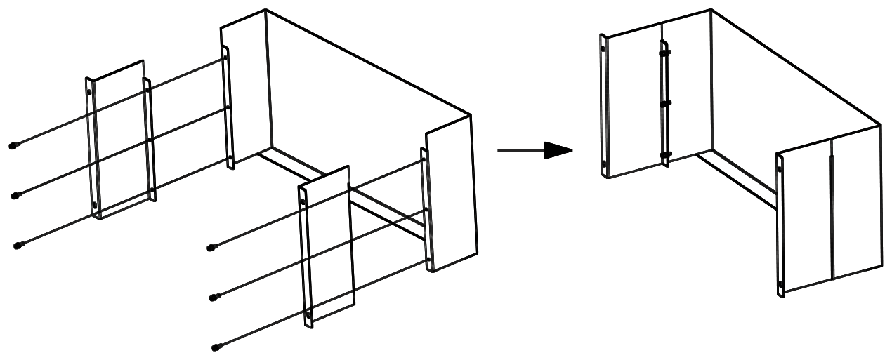
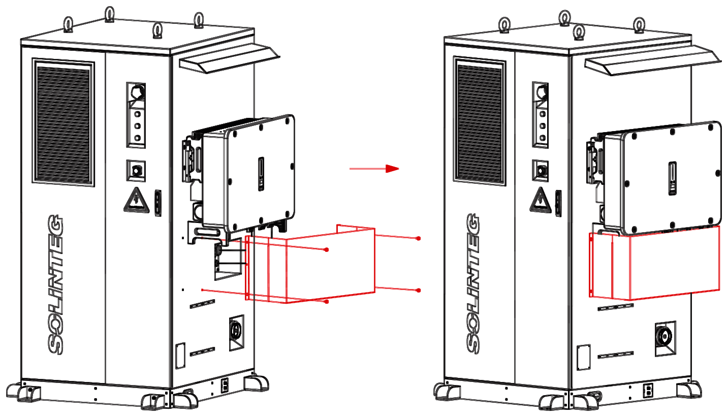
Before connecting the battery terminals, check that the cable polarity is correct.
If the cabinet is to be stored or transported, unplug the main positive and negative battery pack cables first, then close the cabinet.
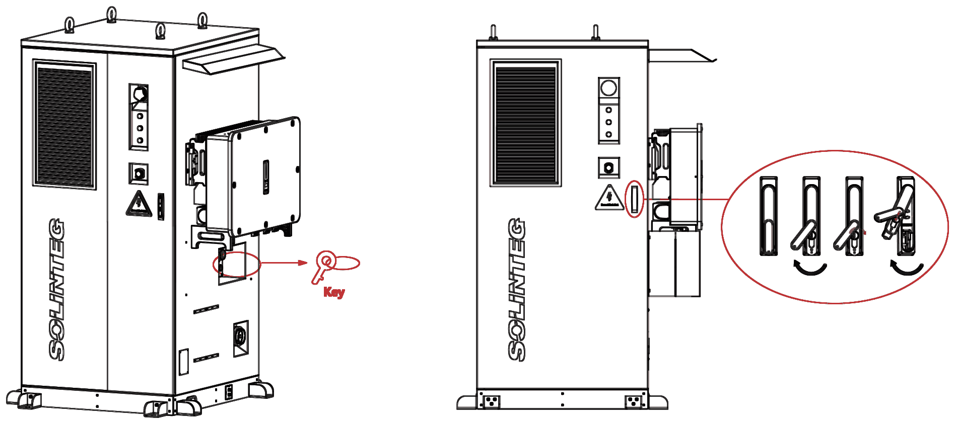
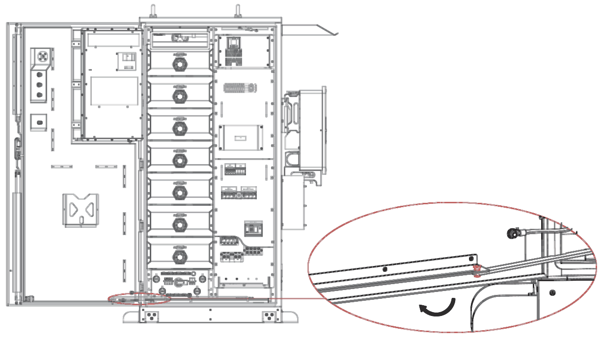
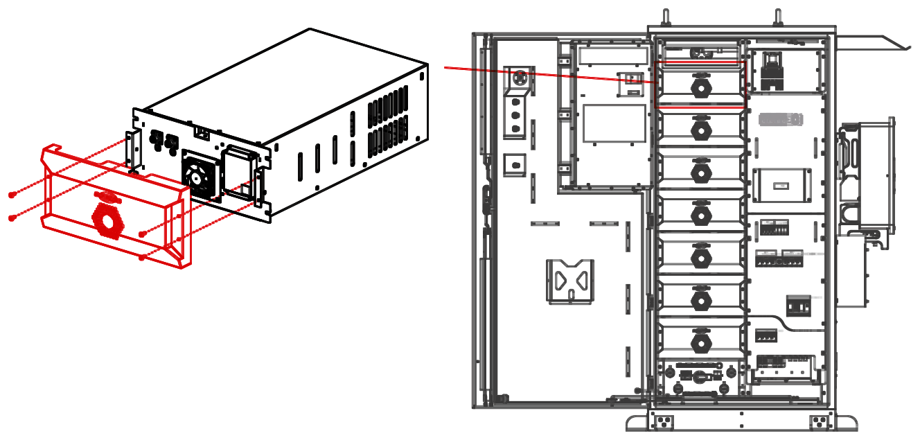
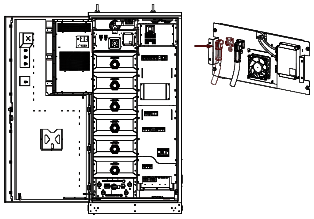
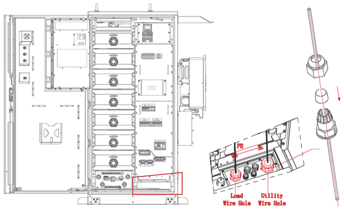
Choose cables to suit the site, using the recommended specifications in section 5.1.2.
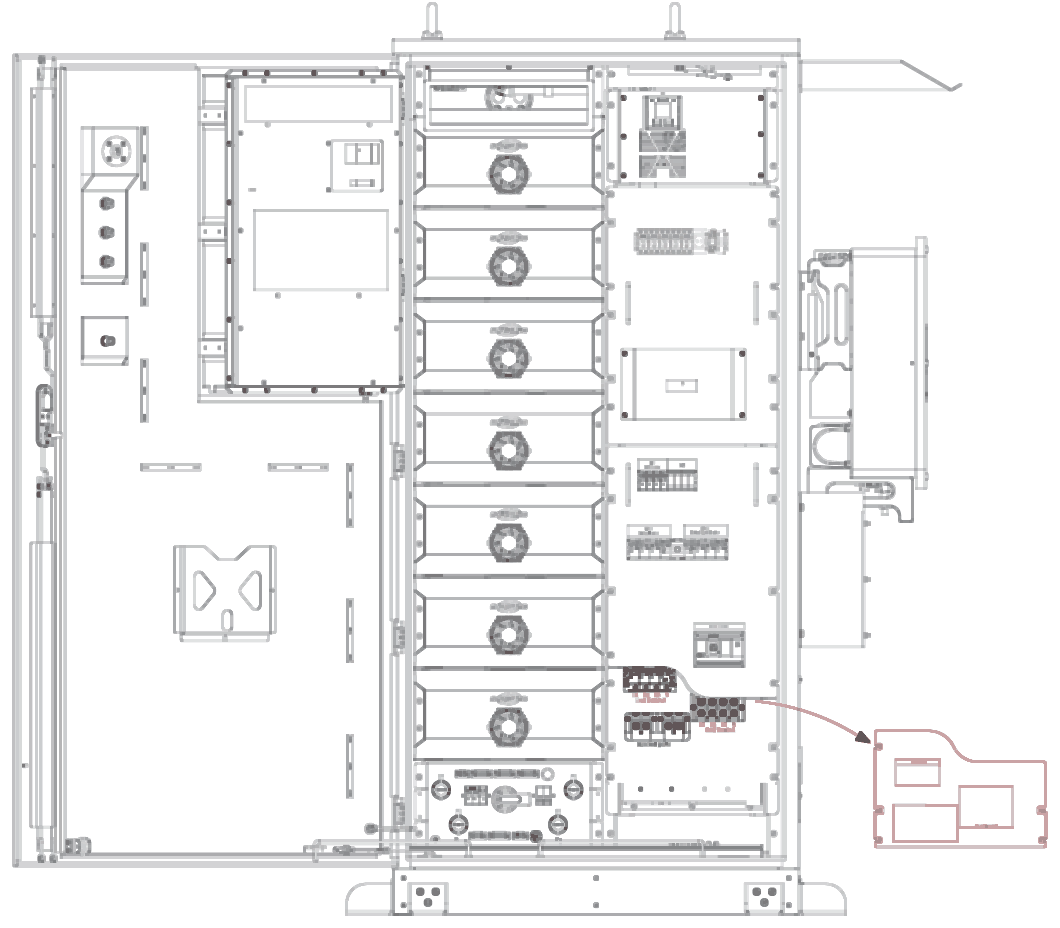
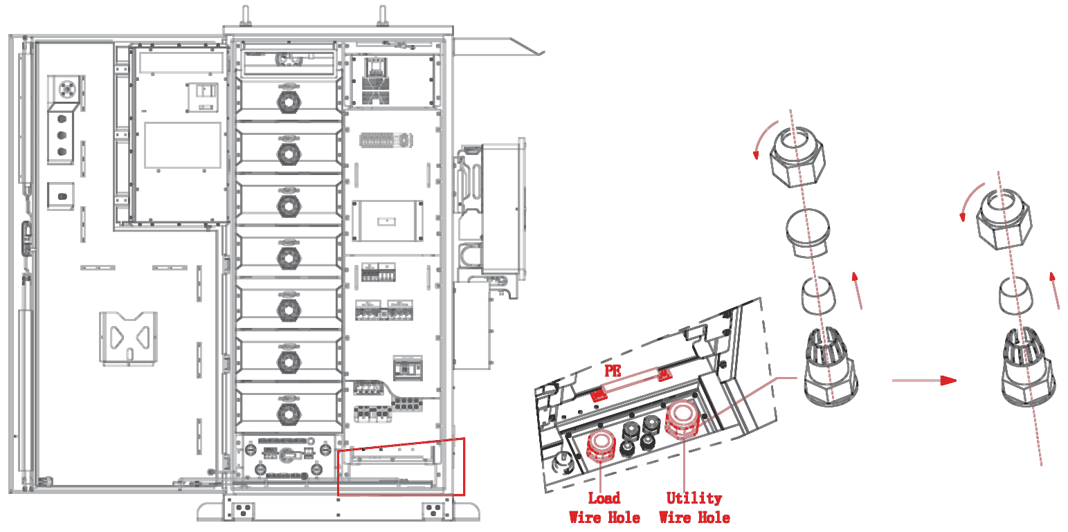
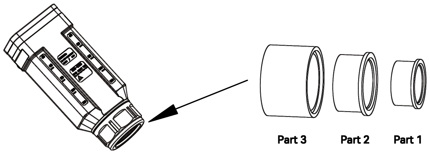
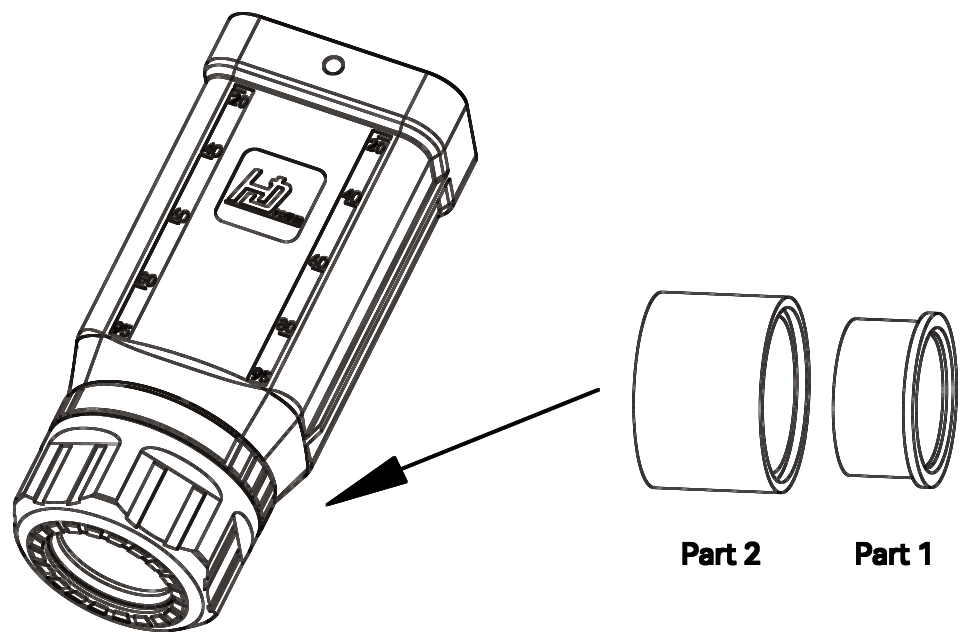
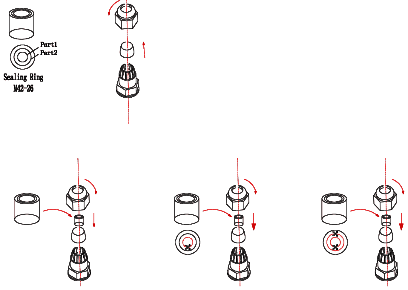
If the cable is smaller than the recommended diameter, seal it with the M42-26 gland sealing ring or the fire-stopping putty from the parts box. Fit the M42-26 sealing ring to suit the cable outside diameter (22–44 mm):
| Cable outside diameter | M42-26 sealing ring |
|---|---|
| Less than 26 mm | Fit the complete sealing ring |
| 26 to 31 mm | Remove part 1 |
| 31 to 35 mm | Remove parts 1 and 2 |
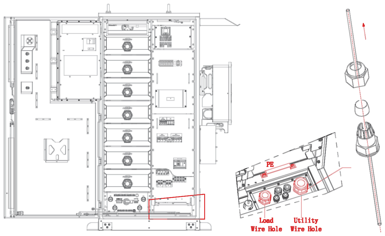
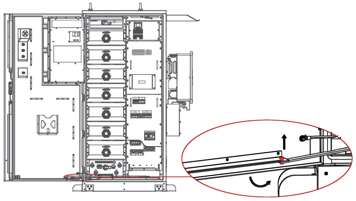
If threading is difficult, remove the base mounting plate as shown below, and refit it after the cables are connected.
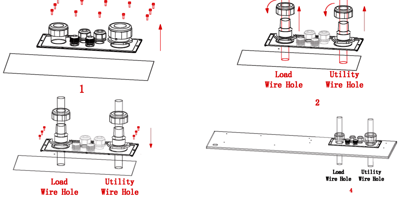
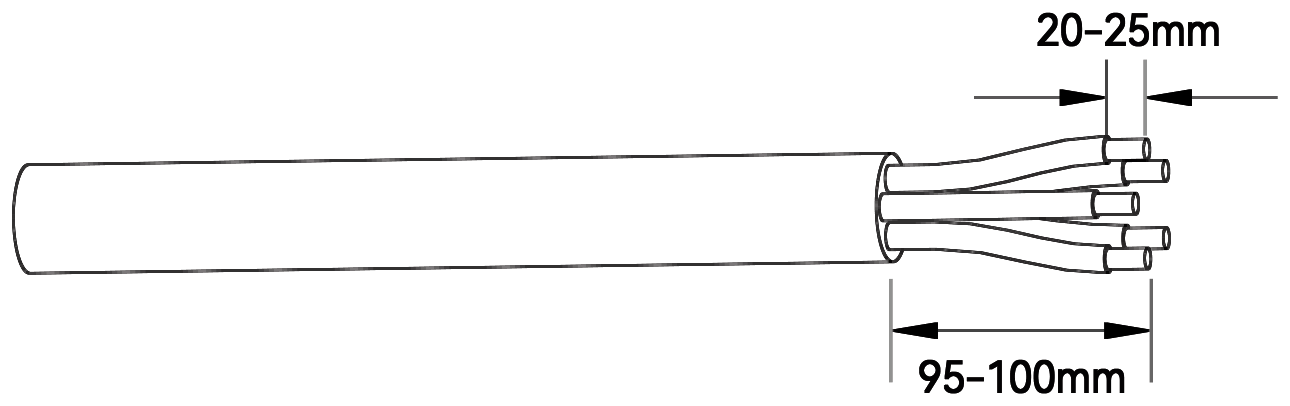
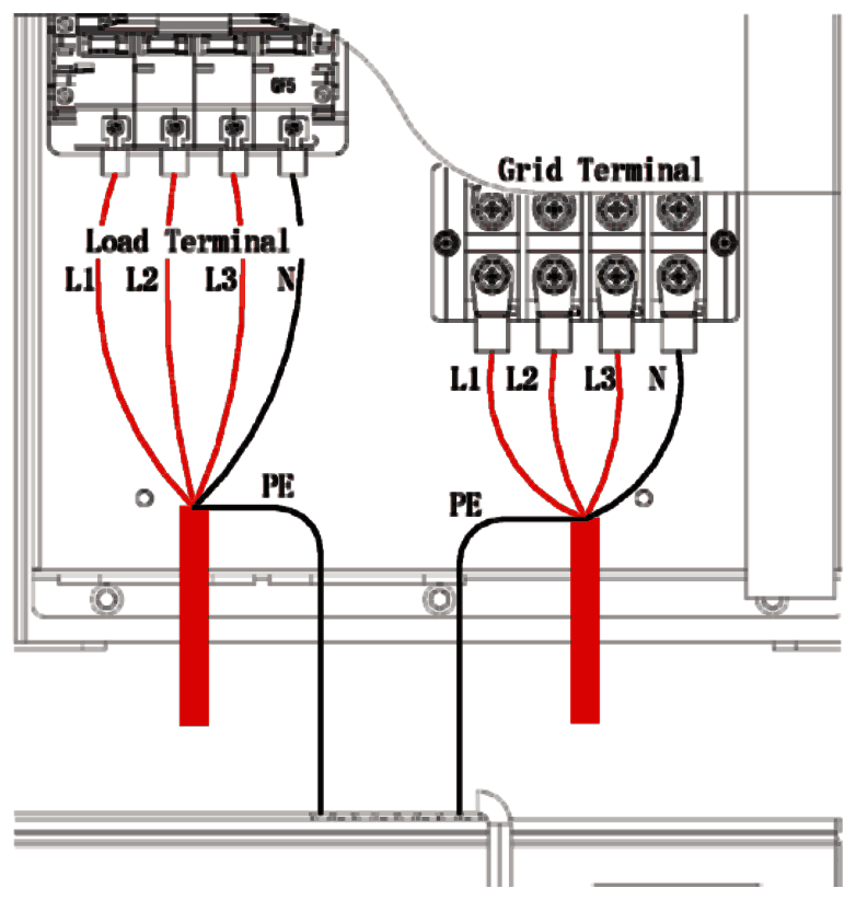
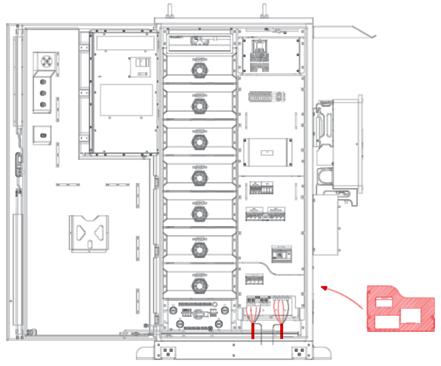
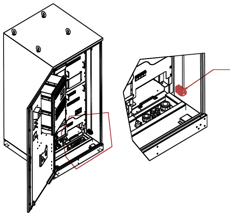
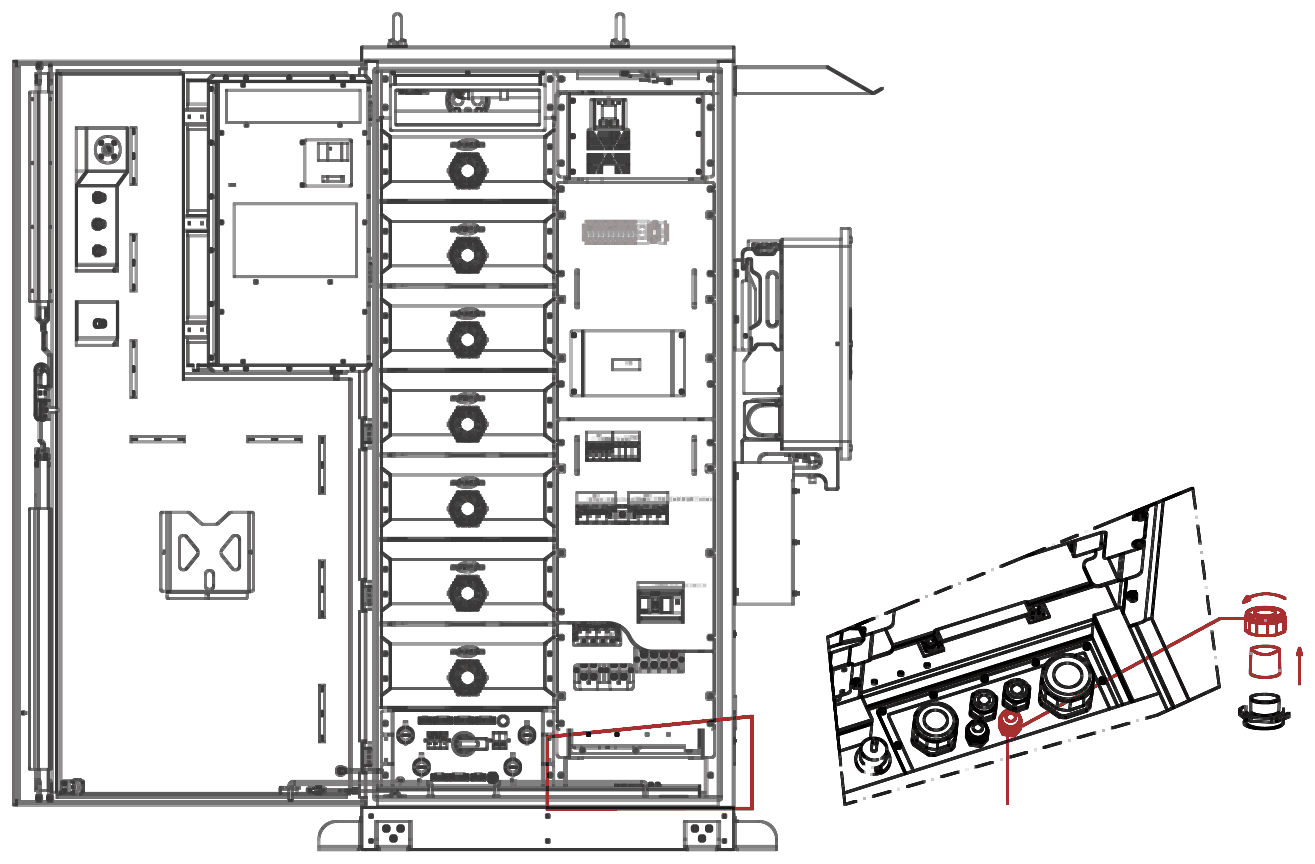
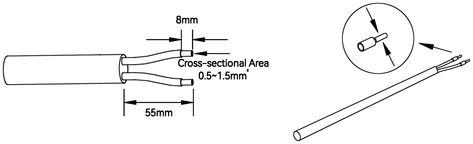
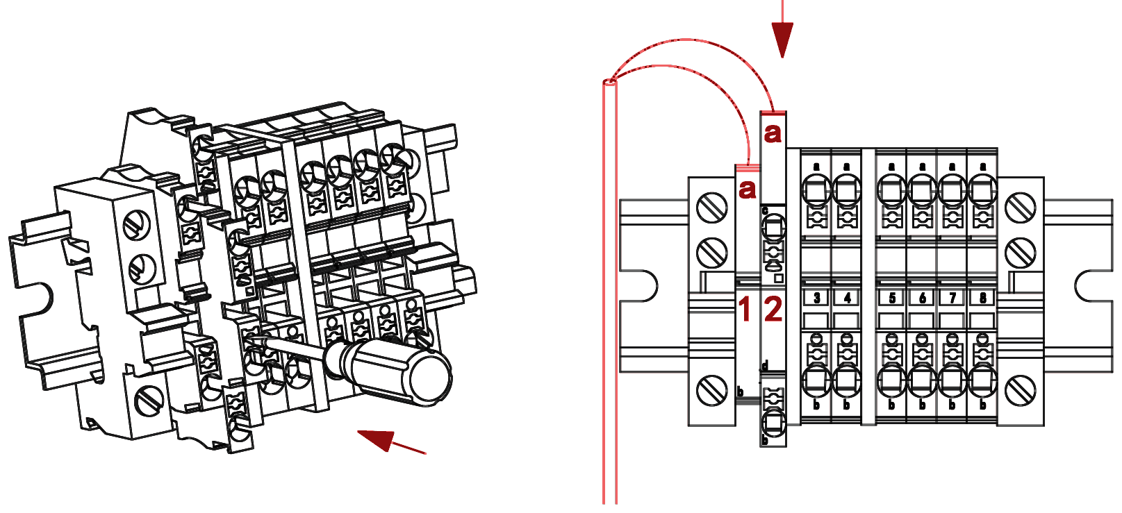
The cabinet's fire-activation signal is a dry contact. Wire it only if the site needs to monitor fire activation remotely.
| Cable | Recommended specification | Cable outside diameter |
|---|---|---|
| Fire signal cable | 2 × 1.0 mm² or 2 × 1.5 mm² | 10–14 mm |
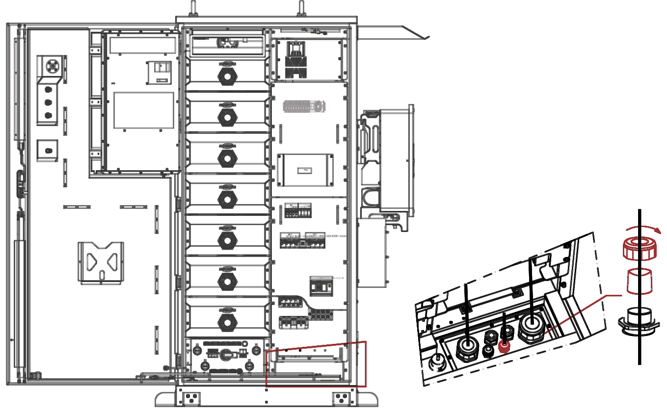
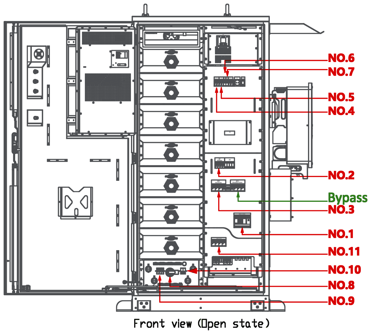
*The first time the UPS is powered, press its power button to start it.
After start-up, check the cabinet status against the table below. If there is a fault alarm, follow section 7.3 or contact AERL support.
| Status | Unit | Indication |
|---|---|---|
| System running normally | Energy storage cabinet | No audible or visual alarm White power indicator on steady Green running indicator on steady Red fault indicator off |
| System running normally | High-voltage box | Red fault indicator off |
In an emergency, press the emergency stop button on the door panel and switch off grid breaker QF4. If the site requires it, also switch off QF821 to cut the UPS output.
After start-up, check that the cabinet is running. If it fails to start, the site may lose power.
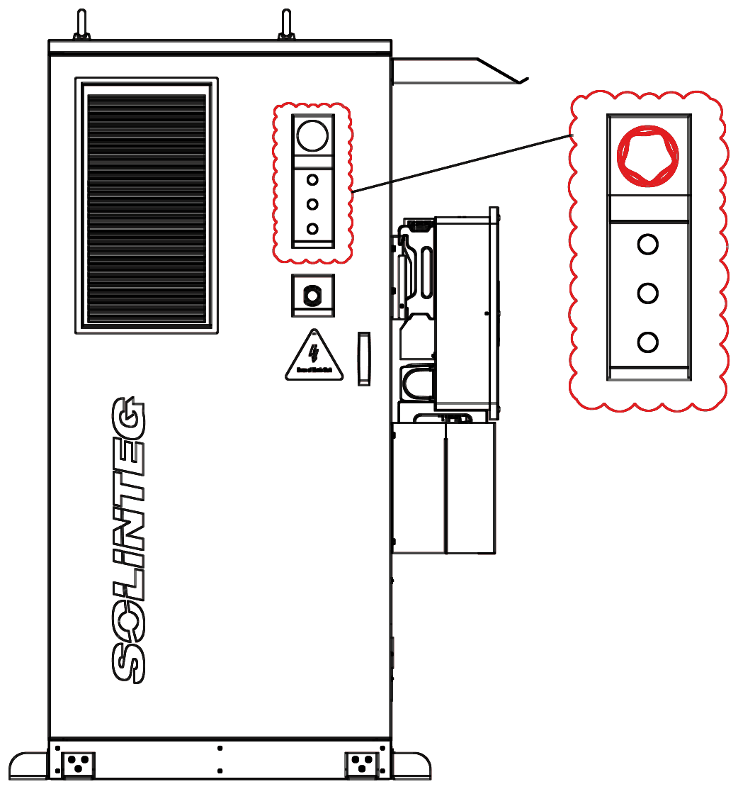
The indicators on the cabinet door show its operating status.
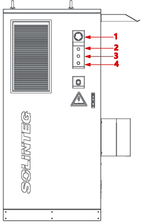
| No. | Indicator | Meaning |
|---|---|---|
| 1 | Audible and visual alarm | Sounds and flashes when the smoke sensor is triggered |
| 2 | Power (white) | On steady while grid power is present |
| 3 | Running (green) | On steady while the high-voltage box is in operation |
| 4 | Fault (red) | On steady when the cabinet has a fault |
If an alarm occurs, check the alarm details in the monitoring data to identify the fault.
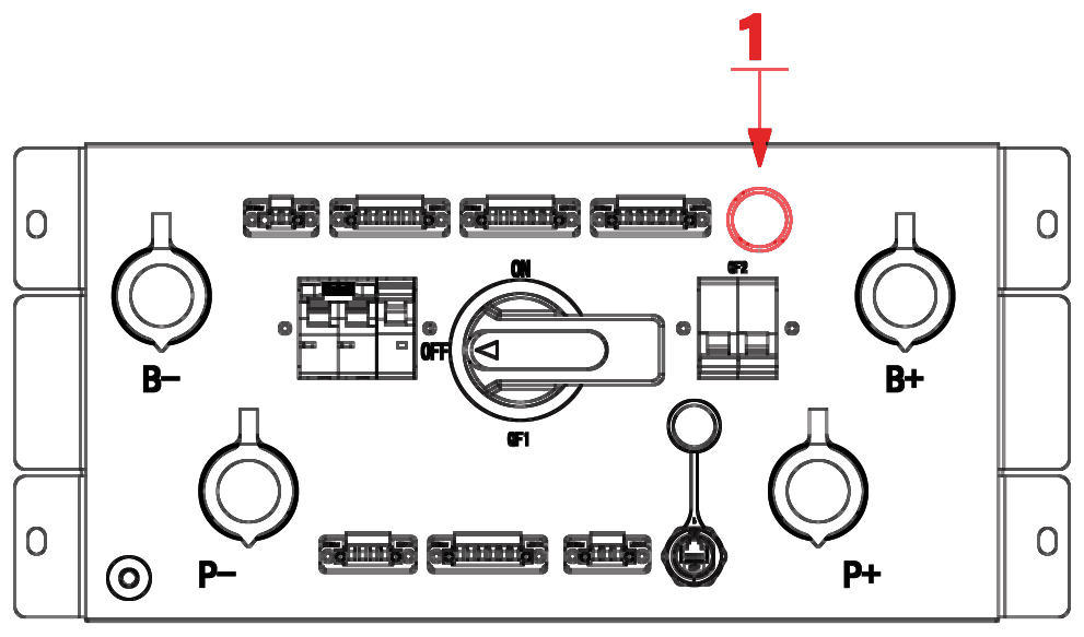
| No. | Indicator | Meaning |
|---|---|---|
| 1 | Fault (red) | On steady when there is a fire fault |
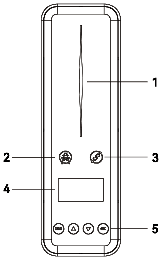
| No. | Indicator | Colour | State | Meaning |
|---|---|---|---|---|
| 1 | Power and alarm | — | Off | No power |
| 1 | Power and alarm | Blue | Fast flashing | Inverter is running its self-test |
| 1 | Power and alarm | Blue | Slow flashing | Inverter is waiting |
| 1 | Power and alarm | Blue | Breathing | Inverter is operating normally |
| 1 | Power and alarm | Orange | Breathing | Low battery: the battery is close to its SOC protection limit |
| 1 | Power and alarm | Red | On | Alarm or fault. Check the fault on the display |
| 2 | Grid | — | Off | Grid lost |
| 2 | Grid | — | Slow flashing | Grid detected, but the inverter is not operating on-grid |
| 2 | Grid | — | On | Inverter is operating on-grid |
| 3 | Communication | Green | On | Communication is normal |
| 3 | Communication | Green | Flashing | Communicating with an EMS or the master inverter over RS485 or CAN |
| 3 | Communication | Orange | On | No communication with the Solinteg smart meter |
| 3 | Communication | Red | On | No communication with the BMS |
| 4 | Display | — | — | Shows operating status and settings. Turns off to save power; press the button to wake it |
| 5 | Button | — | — | Changes the displayed information and sets parameters |
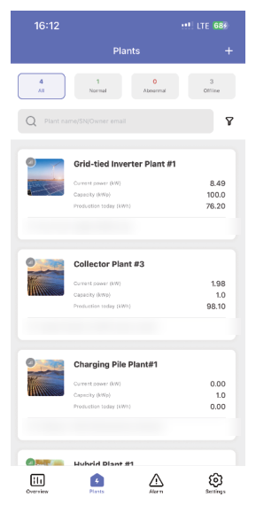
Scan a code to install the free Solinteg IntegHub app, or search for IntegHub in Google Play or the App Store.

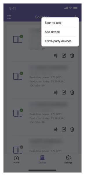
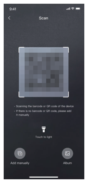
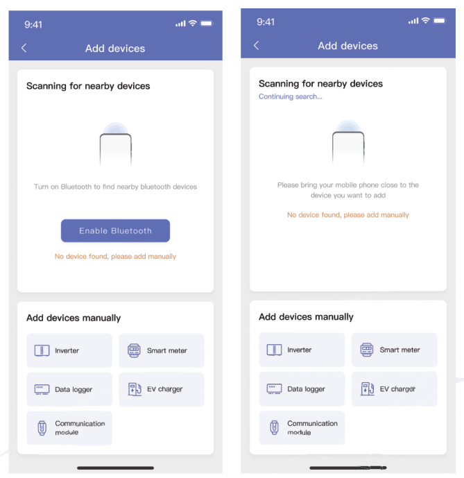
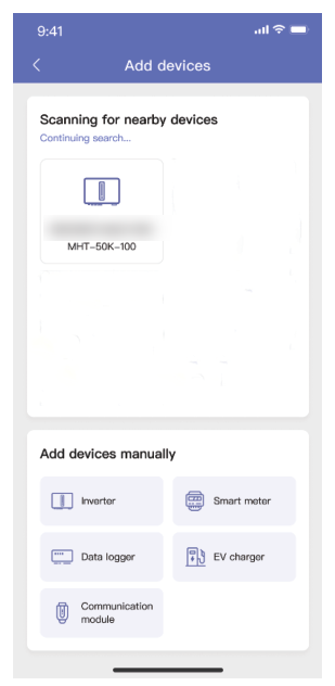
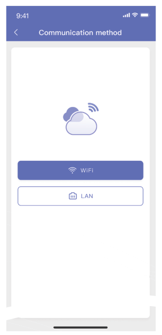
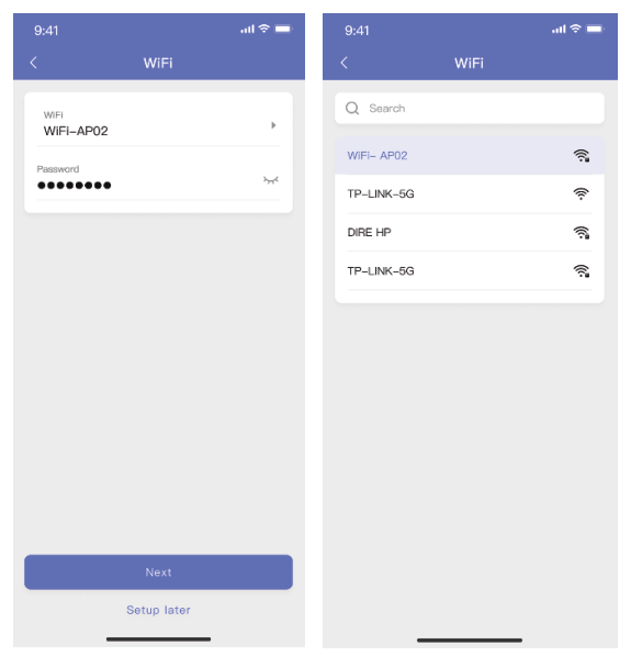
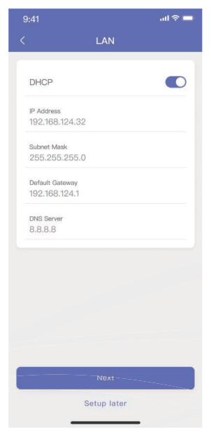
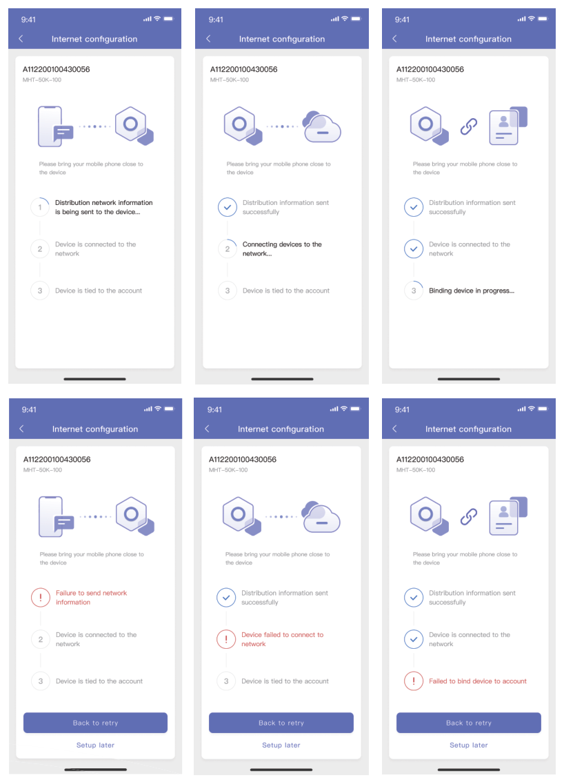
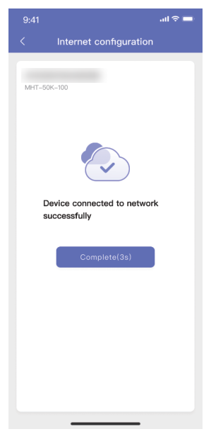
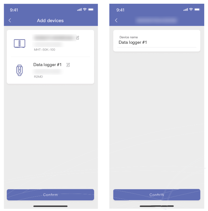
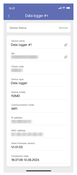
Inspect and maintain the equipment regularly so it keeps working properly. Where the environment or operating conditions are harsh, maintain it more often. Maintenance must be carried out by qualified people.
| Item | What to check | Interval |
|---|---|---|
| Operating environment | Temperature, humidity, corrosion and dust around the equipment Ventilation, and any water around the equipment | 3 months |
| Operating status | Cabinet indicators, and alarms in the monitoring app Any unusual noise, smell or heat | 1 month |
| Cleaning | Dust inside the equipment Air-conditioner inlet and outlet are clear | 3 months |
| Enclosure | Damage to the enclosure Corrosion of structural parts | 3 months |
| Electrical connections | Cable connections are secure Components are securely mounted No signs of arcing or tracking on component surfaces | 6 months |
| Battery packs | No rattling, deformation or leaks In storage: no more than six months between top-up charges, and SOC never below 10% | 1 month |
| Fire-protection equipment | Service and replacement by qualified people to local fire requirements | As required locally |
| Cables | If a cable at the side cable panel is damaged, have it replaced by a qualified person with cable to the specification in section 5.1.2 | As required |
The cabinet paint may be damaged by knocks during handling, transport and installation. Repair it as follows.
If the damaged area is large, contact a professional for repair.
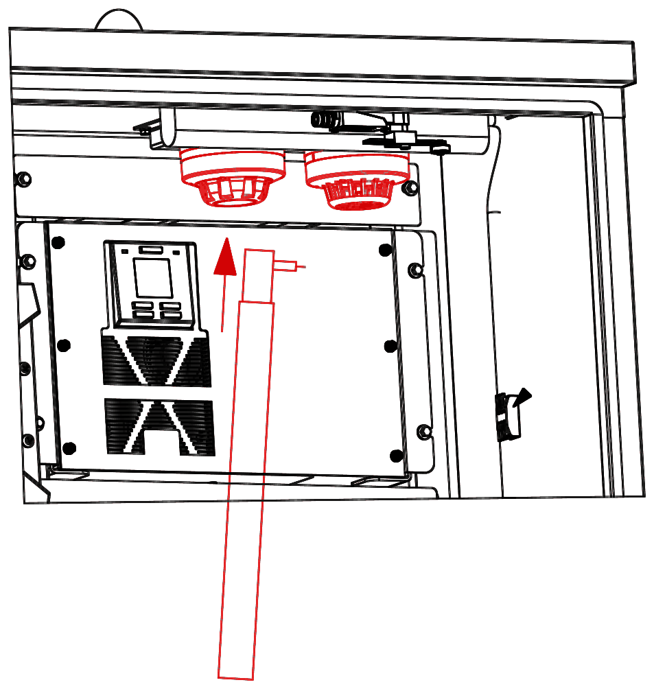
Only qualified people may inspect the fire-protection system. A failed fire-protection system can cause injury, death or damage. Use proper fire-detection test equipment, so the smoke and temperature sensors are not contaminated. Before any fire-detection test, disconnect the fire test terminal in the cabinet. Otherwise the extinguisher will discharge and damage the equipment.
Troubleshooting must be carried out by qualified people in accordance with local requirements. Where the table says to contact AERL support, call 1800 950 865 or email [email protected].
Codes starting with E are protection faults. The battery stops to protect itself. Codes starting with I are alarms and codes starting with W are warnings. The system keeps running, but the condition needs attention.
| Code | Name | Cause | Action |
|---|---|---|---|
| E400 | BMS communication | No communication between the controller and the inverter | 1. Check that the correct battery type is selected in the inverter. 2. Check the battery operating status. 3. Check the communication connection between the inverter and the BMS. 4. Check the wiring order (pinout) of the communication cable. |
| E431 | Battery voltage abnormal | The battery voltage measured by the inverter differs from the value reported by the BMS by more than 100 V | 1. Check that the power cables are connected correctly. 2. Check the power cables for leakage or damage. 3. Check for battery alarms or protection. 4. Clear the problem, then restart the battery. If it persists, contact AERL support. |
| E432 | Battery parallel number abnormal | The number of battery clusters detected in parallel differs from the configured target | 1. Check the target number. If it is wrong, correct it. 2. Check for communication faults between the batteries or clusters and the inverter. Fix them, then re-run the paralleling process. 3. Check that every cluster is powered. If not, switch on the DC breaker of each battery or cluster and re-run the paralleling process. 4. Check every cluster for alarms or protection. Clear them, then re-run the paralleling process. 5. Check that the voltage difference between batteries or clusters is no more than 2.5 V. If not, charge or discharge them until it is, then re-run the paralleling process. |
| E401 | Low SOC | The battery is over-discharged (SOC below 5% or the set value) | 1. Check the communication and power connections between the battery and the inverter. 2. Check the inverter's connections to PV, the grid and the generator. 3. Check whether the load is too large. |
| E402 | Low SOH | The battery state of health is too low | 1. Check whether the battery has gone a long time without a complete charge–discharge cycle. 2. Check for performance differences between cells. 3. Check for performance differences between batteries. |
| Code | Name | Cause | Action |
|---|---|---|---|
| E403 | BMS sleeping | A threshold was reached and the BMS went to sleep | 1. Check that the grid or PV can supply stable power for long enough. 2. Check the power connection between the battery and the inverter. |
| E404 | Battery voltage sensor fault | Possible fault in the battery voltage sensing | 1. Restart the battery. 2. If it persists, contact AERL support. |
| E405 | Battery temperature sensor fault | Possible fault in the battery temperature sensing | 1. Restart the battery. 2. If it persists, contact AERL support. |
| E406 | Battery internal communication fault | Possible fault in the battery's internal communication circuit | 1. Check the communication cable between the battery modules and the controller. 2. Restart the battery. If it persists, contact AERL support. |
| E407 | Input overvoltage | The voltage at the battery input is too high | 1. Check that the power cables are not connected to another source. 2. Check the inverter for a fault. |
| E408 | Input reverse polarity | The input polarity is reversed | 1. Check whether the power cables are connected the wrong way round. 2. Check the inverter for a fault. |
| E409 | Battery relay fault | Possible fault in the battery relay | 1. Restart the battery. 2. If it persists, contact AERL support. |
| E410 | Damaged cell | A cell voltage is below 2.0 V | 1. Restart the battery. 2. If it persists, contact AERL support. |
| E411 | Shut-down circuit fault | The system cannot switch off completely | 1. Restart the battery. 2. If it persists, contact AERL support. |
| E412 | BMIC fault | The sensing chip is faulty | 1. Restart the battery. 2. If it persists, contact AERL support. |
| E413 | Battery internal bus fault | The battery's internal bus is faulty | 1. Restart the battery. 2. If it persists, contact AERL support. |
| E414 | Self-test fault | The self-test failed | 1. Restart the battery. 2. If it persists, contact AERL support. |
| E415 | Safety function fault | The chip self-test failed | 1. Restart the battery. 2. If it persists, contact AERL support. |
| E416 | Insulation fault | Insulation resistance is too low | 1. Shut down the whole system. 2. Check the equipment, cables and terminals for damage or breaks. 3. Check for short circuits caused by foreign objects. 4. Clear the problem, then restart the battery. If it persists, contact AERL support. |
The following conditions each have three levels: protection (E), alarm (I) and warning (W).
| Codes | Name | Cause | Action |
|---|---|---|---|
| E417 I400 W400 | Cell undervoltage | A cell voltage is too low | 1. Check the inverter for a fault or incorrect setting that prevents forced charging or lets the battery keep discharging. 2. Check whether the external source (PV, grid or generator) has stopped, which prevents forced charging. 3. Charge the battery immediately (for E417, restart the battery first). 4. I400/W400: check for a large voltage difference between cells. If there is one, fully charge and discharge the battery several times (more than 10 cycles). If it persists, contact AERL support. |
| E418 I401 W401 | Cell overvoltage | A cell voltage is too high | 1. Check the inverter for a fault or incorrect setting that ignores the charge voltage limit or prevents forced discharging. 2. Check the settings and configuration. 3. Discharge the battery immediately (for E418, restart the battery first). 4. I401/W401: check for a large voltage difference between cells. If there is one, fully charge and discharge the battery several times (more than 10 cycles). If it persists, contact AERL support. |
| E419 I402 W402 | Cluster undervoltage | The battery cluster voltage is too low | 1. Check the inverter for a fault or incorrect setting that prevents forced charging or lets the battery keep discharging. 2. Check whether the external source (PV, grid or generator) has stopped. 3. Check whether the load is too large. 4. Charge the battery immediately (for E419, restart the battery first). |
| E420 I403 W403 | Cluster overvoltage | The battery cluster voltage is too high | 1. Check the inverter for a fault or incorrect setting that ignores the charge voltage limit or prevents forced discharging. 2. Check the settings and configuration. 3. Discharge the battery immediately (for E420, restart the battery first). |
| E427 I410 W410 | Module undervoltage | A battery module voltage is too low | 1. Check the inverter for a fault or incorrect setting that prevents forced charging or lets the battery keep discharging. 2. Check whether the external source has stopped, or the load is too large. 3. Charge the battery immediately (for E427, restart the battery first). |
| Codes | Name | Cause | Action |
|---|---|---|---|
| E428 I411 W411 | Module overvoltage | A battery module voltage is too high | 1. Check the inverter for a fault or incorrect setting that ignores the charge voltage limit or prevents forced discharging. 2. Check the settings and configuration. 3. Discharge the battery immediately (for E428, restart the battery first). |
| E421 I404 W404 | Charge undertemperature | The battery is too cold to charge | 1. Check that the battery temperature reading is plausible. 2. Check the temperature sensors for a fault. 3. Raise the ambient temperature to warm the battery (for E421, then restart the battery). |
| E422 I405 W405 | Charge overtemperature | The battery is too hot to charge | 1. Check that the battery temperature reading is plausible. 2. Check the temperature sensors for a fault. 3. Lower the ambient temperature to cool the battery, or reduce the charge current (for E422, then restart the battery). |
| E423 I406 W406 | Discharge undertemperature | The battery is too cold to discharge | 1. Check that the battery temperature reading is plausible. 2. Check the temperature sensors for a fault. 3. Raise the ambient temperature to warm the battery (for E423, then restart the battery). |
| E424 I407 W407 | Discharge overtemperature | The battery is too hot to discharge | 1. Check that the battery temperature reading is plausible. 2. Check the temperature sensors for a fault. 3. Lower the ambient temperature to cool the battery, or reduce the discharge current (for E424, then restart the battery). |
| E425 I408 W408 | Charge overcurrent | The charge current is too high | 1. Check whether the battery's current limit has been reduced because of temperature, SOC or similar. 2. Check whether the inverter is charging above the current limit. 3. Check or correct the inverter configuration, then restart the battery. |
| E426 I409 W409 | Discharge overcurrent | The discharge current is too high | 1. Check whether the battery's current limit has been reduced because of temperature, SOC or similar. 2. Check whether the inverter is discharging above the current limit. 3. Check or correct the inverter configuration, then restart the battery. |
| Codes | Name | Cause | Action |
|---|---|---|---|
| E429 I412 | Terminal overtemperature | A terminal temperature is too high | 1. Check that the terminal temperature reading is plausible. 2. Check the temperature sensors for a fault. 3. Lower the ambient temperature to cool the terminal, then restart the battery. |
| E430 I414 | Leakage current | Leakage current is too high | 1. Shut down the whole system. 2. Check the equipment, cables and terminals for damage or breaks. 3. Check for short circuits caused by foreign objects. 4. Clear the problem, then restart the battery. |
| Code | Name | Cause | Action |
|---|---|---|---|
| I413 | Fan fault | A battery module fan is faulty | 1. Turn off the battery and check that the fan power cable is connected correctly. 2. Contact AERL support. |
| W412 | BMU offline | A BMU in a battery module is offline | Turn off the battery and contact AERL support. |
| W413 | BMCU offline | The BMCU in the controller is offline | Turn off the battery and contact AERL support. |
| W414 | Module serial number changed | A battery module has been changed | 1. Check whether a battery module has been removed or added. 2. Check that all modules had the same SOC and voltage when they were added. 3. Contact your installer or AERL support to confirm and clear the warning. |
| W415 | Cluster voltage change | The cluster voltage changed too much within 2 s | 1. Check that the power cables are connected correctly. 2. Check for abnormal changes in voltage and SOC. 3. Clear the problem, then restart the battery. If it persists, contact AERL support. |
| W416 | Cluster voltage difference | There is a large voltage difference between clusters | 1. Check that the power cables are connected correctly. 2. Check for abnormal changes in voltage and SOC. 3. Check that every cluster has the same battery model and number of modules. 4. Clear the problem, then restart the battery. If it persists, contact AERL support. |
| W417 | Module voltage difference | There is a large voltage difference between battery modules | 1. Check that the power cables are connected correctly. 2. Check for abnormal changes in voltage and SOC. 3. Clear the problem, then restart the battery. If it persists, contact AERL support. |
The cabinet contains lithium-ion batteries. Do not dispose of it in general waste. Dispose of the cabinet and its batteries through a licensed e-waste or battery recycler, in accordance with the requirements of your state or territory environmental regulator. Contact AERL for advice on returning or recycling batteries.
Contact AERL for help with installation, commissioning, alarms, warranty and spare parts for the All-In-One in Australia.
When you contact AERL, have the following ready:
Australian Energy Research Laboratories
1/75 Bluestone Circuit
Seventeen Mile Rocks QLD 4073
Australia