 Download PDF· Rev 2.0.2
Installation and Operation User Manual
Battery Sense
Remote Temperature and Voltage Sensor
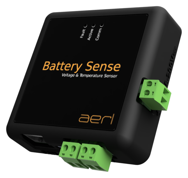
BAT-SENSE
Installation and Operation User ManualRev 2.0.2, 8 Nov 2026
Download PDF· Rev 2.0.2
Installation and Operation User Manual
Remote Temperature and Voltage Sensor
Australian Energy Research Laboratories (AERL) was founded in 1985 by Stuart Watkinson to commercialise the Power Optimizer, which he developed while studying at the University of Queensland. It became the AERL MAXIMIZER™, a universal maximum power point tracker (MPPT).
Today AERL designs, integrates and supports power conversion, lithium energy storage, monitoring and earth-fault detection products for commercial, industrial and off-grid energy systems, including oil and gas, mining and telecommunications sites.
AERL and the AERL logo are trademarks owned by AERL Holdings Pty Ltd and used by AERL Pty Ltd under licence. These trademarks may be registered in Australia and other countries.
November 2026 (11/2026)
CoolMax Battery Sense User Manual © 2026 AERL Pty Ltd. All rights reserved.
UNLESS SPECIFICALLY AGREED TO IN WRITING, AERL PTY LTD:
(a) MAKES NO WARRANTY AS TO THE ACCURACY, SUFFICIENCY OR SUITABILITY OF ANY TECHNICAL OR OTHER INFORMATION PROVIDED IN ITS MANUALS OR OTHER DOCUMENTATION.
(b) ASSUMES NO RESPONSIBILITY OR LIABILITY FOR LOSS OR DAMAGE, WHETHER DIRECT, INDIRECT, CONSEQUENTIAL, OR INCIDENTAL, WHICH MIGHT ARISE OUT OF THE USE OF SUCH INFORMATION.
THE USE OF ANY SUCH INFORMATION WILL BE ENTIRELY AT THE USER'S RISK.
Australian Energy Research Laboratories, 1/75 Bluestone Circuit, Seventeen Mile Rocks QLD 4073, Australia
aerl.com.au · [email protected] · 1800 950 865
This manual contains important safety information and installation instructions for the AERL Battery Sense remote temperature and voltage sensor. It uses the following symbols for important operating information and potentially dangerous conditions.

Indicates information that must be followed to ensure proper installation or operation of the Battery Sense.

Indicates a critical procedure for the safe installation or operation of the Battery Sense.
This manual gives installation and operating instructions for the Battery Sense. Read all of its instructions and cautions before you start the installation.
Only qualified electricians and technicians may install the Battery Sense. This manual is for installers and the system owner.
Do not disassemble or attempt to repair the Battery Sense unless you are a qualified technician and have authority in writing from AERL to do so.
AERL will not be held responsible in any way for the mishandling of this product or for installation of the product in a manner that does not follow the instructions in this manual or as advised by AERL.
| Warranty requirements | Total warranty duration |
|---|---|
| You are the original purchaser of the Battery Sense. | 2 years |
The warranty starts 30 days after AERL dispatches the Battery Sense.
Our goods come with guarantees that cannot be excluded under the Australian Consumer Law. You are entitled to a replacement or refund for a major failure and compensation for any other reasonably foreseeable loss or damage. You are also entitled to have the goods repaired or replaced if the goods fail to be of acceptable quality and the failure does not amount to a major failure.
Full terms: AERL warranty statement for the CoolMax Battery Sense, aerl.com.au.
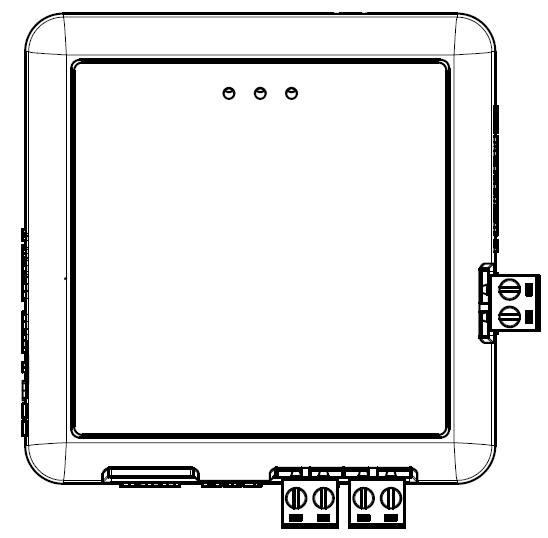
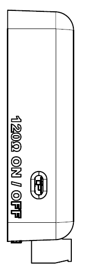
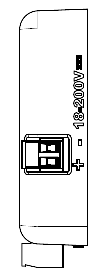
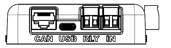
| Parameter | Typical |
|---|---|
| Weight | 0.25 kg |
| Dimensions (W × H × D) | 15 × 15 × 3 cm |
| Enclosure Type | Indoor Type 1 / IP20 |
| Mounting Method | Double-sided Adhesive Tape |
| Voltage Input Connector | Screw terminals (0.5–2.5 mm²) |
| Parameter | Specification |
|---|---|
| Voltage Input Range | 18–200 Vdc |
| Communication Interface | CAN Bus (RJ45) |
| Maximum Cable Length | 10 metres |
| Power Supply | 5 V (via CoolMax CAN port) |
| Float Indication Output Relay | 12 V / 2 A (fused) |
| Float Switch Input | Normally Open (NO), voltage-free contacts |
| Termination | 120 Ω (switchable) |
| Status Indicators | Active (Green Heartbeat), Fault (Red), CAN Activity (Yellow Blinking) |
| Max Altitude Rating | 2000 m |
| Storage Temperature | −30 to 70 °C |
| Self-Consumption @ Idle | 0.1 W |
| Allowable Relative Humidity | 95% (Non-Condensing) |
| Ambient Operating Temperature Range | −20 to 50 °C |
| Designed to meet | EN 61000-6-3:2012 EN 61000-6-4:2012 |
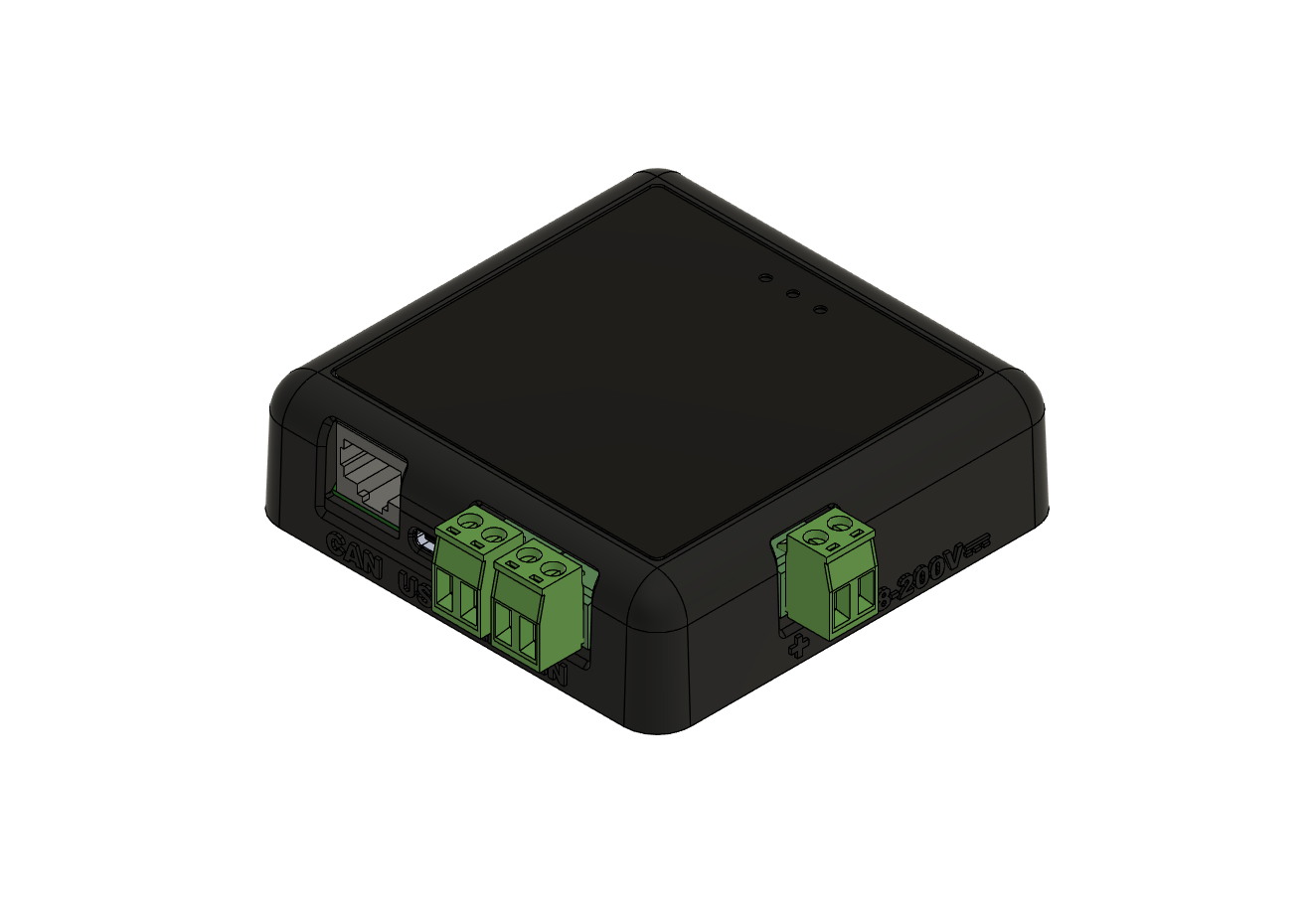
Thank you for purchasing an Australian made Battery Sense Remote Temperature and Voltage Sensor.
The Battery Sense is an accessory for AERL CoolMax solar charge controllers. It measures battery temperature and voltage at the battery, so the controller can compensate its charging for temperature and monitor the battery more accurately.
With a CoolMax SRX controller, the Battery Sense provides:
All installations must comply with national and local electrical standards and codes of practice.
AERL recommends professional installation. No ongoing maintenance is required.
The Battery Sense must be installed in a clean, dry location away from direct sunlight on a flame retardant or non-flammable surface.
Ensure all circuit breakers are in the OFF position before connecting or disconnecting the Battery Sense.
Use the pre-applied double-sided tape on the back of the Battery Sense to mount it on a vertical surface near the battery bank.
When selecting a mounting location, consider the following:
To mount the device:
When mounting the Battery Sense, a clearance zone around the device should be maintained for optimal operation:
This clearance ensures proper air circulation and access for wiring connections.
Use a minimum of #18 AWG (0.75 mm²) high strand count double insulated cable for the voltage sense connection between the Battery Sense and the battery terminals.
Torque all Battery Sense wire terminals to 0.5 Nm (4.4 in-lb).
Always install appropriate fusing for the voltage sense connection near the battery terminals.
Reversing the polarity of the voltage sense connection may damage the Battery Sense and void product warranty.
Confirm polarity with a multimeter before you connect the voltage sense wires.
The Battery Sense connects to the CoolMax SRX controller via one of the CAN bus RJ45 ports.
Use only high-quality CAT6 cables for reliable communication. Maximum cable length is 10 metres.
Once properly connected, the Battery Sense will automatically begin transmitting temperature and voltage data to the CoolMax SRX controller.
The Battery Sense features three LED indicators to provide visual status information:
| LED | State | Meaning |
|---|---|---|
| Green (Active) | Slow heartbeat (brief flash every ~1.5 s) | Device is powered and operating normally |
| Green (Active) | Off | Device is not powered |
| Red (Fault) | Solid On | Fault condition detected (e.g. watchdog initialisation failure) |
| Red (Fault) | Brief 3× flash | Float event acknowledgement (Float Switch Input closed, or float charge state received from a CoolMax SRX) |
| Red (Fault) | Off | Normal operation |
| Yellow (CAN Activity) | Brief blink | A CAN message has been transmitted or received |
| Yellow (CAN Activity) | Off | No CAN bus activity |
At power-on, all three LEDs illuminate briefly as a self-test, then return to their normal states.
The LED indicators are located on the front of the device and are visible through the transparent cover.
Temperature compensation measures the temperature of the batteries and adjusts the float and absorb voltage set points to the ideal voltage for batteries at that temperature.
Using the temperature of the batteries, the CoolMax SRX adjusts voltages by a factor in millivolts per °C, set in AERL Link. The factor is per bank, not per cell; the factory default is 50 mV/°C.
The CoolMax SRX compensates whenever it has a battery temperature reading, from the Battery Sense or from a battery BMS over CAN. Without one, it charges to the uncompensated set points.
To configure temperature compensation:
Temperature compensation is particularly important for:
The Battery Sense provides accurate battery voltage readings directly from the battery terminals, allowing the CoolMax SRX to:
The voltage monitoring function works automatically once the Battery Sense is properly connected and the voltage sense wires are connected to the battery terminals.
The Battery Sense includes a Float Switch Input that allows external systems to signal when the battery has reached float stage. This is useful for synchronising multiple charging sources.
Do not apply any voltage to the Float Switch Input terminals. This input is designed for a voltage-free contact closure only.
The Battery Sense provides a Float Indication Output relay that activates when the CoolMax SRX controller enters float charging mode.
Do not exceed the 12 V / 2 A rating of the Float Indication Output relay. For higher loads, use an appropriately rated intermediate relay.
Use the LED indicators to diagnose a problem; their states are listed under LED Status Indicators in the Operation chapter.
| Issue | Possible causes | Solution |
|---|---|---|
| Green LED not flashing | - 5 V power toggle on SRX not enabled - Poor connection to CoolMax SRX - Faulty CAT6 cable | - Ensure 5 V power toggle on SRX is ON - Check cable connections - Try a different CAT6 cable |
| Red Fault LED solid on | - Internal device fault (e.g. watchdog initialisation failure) - Voltage sense connection issue - Voltage out of range | - Power-cycle the device - Check voltage sense connections - Verify battery voltage is within 18–200 Vdc range - Contact AERL support |
| Yellow LED not blinking | - No CAN traffic on the bus - CAN bus configuration problem | - Check cable connections - Verify 120 Ω termination switch positions - Restart the CoolMax SRX |
| Temperature not showing in AERL Link | - 120 Ω termination not enabled - Communication issue - Device fault | - Set 120 Ω termination switch to ON - Check cable connections - Verify green LED is illuminated |
| Incorrect voltage reading | - Poor voltage sense connection - Improperly sized fuse - Voltage sense wire damage | - Check voltage sense connections - Verify appropriate fusing - Inspect wiring for damage |
| Float switch input not working | - Improper connection - External voltage applied | - Verify switch is normally open type - Ensure no voltage is applied to terminals - Check continuity of float switch |
| Float indication output not working | - Exceeding 12 V / 2 A rating - Blown fuse - Connection issue | - Verify connected load is within rating - Check/replace fuse - Verify connections |
If your situation is not covered here, contact AERL support on 1800 950 865 or at [email protected].
Australian Energy Research Laboratories
1/75 Bluestone Circuit
Seventeen Mile Rocks QLD 4073
Australia