Australian Energy Research Laboratories (AERL) was founded in 1985 by Stuart Watkinson to commercialise the Power Optimizer, which he developed while studying at the University of Queensland. It became the AERL MAXIMIZER™, a universal maximum power point tracker (MPPT).
Today AERL designs, integrates and supports power conversion, lithium energy storage, monitoring and earth-fault detection products for commercial, industrial and off-grid energy systems, including oil and gas, mining and telecommunications sites.
Trademark
AERL and the AERL logo are trademarks owned by AERL Holdings Pty Ltd and used by AERL Pty Ltd under licence. These trademarks may be registered in Australia and other countries. NOARK and other third-party names are trademarks of their respective owners.
UNLESS SPECIFICALLY AGREED TO IN WRITING, AERL PTY LTD:
(a) MAKES NO WARRANTY AS TO THE ACCURACY, SUFFICIENCY OR SUITABILITY OF ANY TECHNICAL OR OTHER INFORMATION PROVIDED IN ITS MANUALS OR OTHER DOCUMENTATION.
(b) ASSUMES NO RESPONSIBILITY OR LIABILITY FOR LOSS OR DAMAGE, WHETHER DIRECT, INDIRECT, CONSEQUENTIAL, OR INCIDENTAL, WHICH MIGHT ARISE OUT OF THE USE OF SUCH INFORMATION.
THE USE OF ANY SUCH INFORMATION WILL BE ENTIRELY AT THE USER'S RISK.
Contact Information
Australian Energy Research Laboratories, 1/75 Bluestone Circuit, Seventeen Mile Rocks QLD 4073, Australia
This manual contains important safety information and installation instructions for the AERL CoolMax SRX MV 300 MPPT solar charge controller. It uses the following symbols for important operating information and potentially dangerous conditions.
Important
Indicates information that must be followed to ensure proper installation or operation of the CoolMax SRX.
Caution
Indicates a critical procedure for the safe installation or operation of the CoolMax SRX. Take extreme care when you carry out this task.
1.1About This Manual
This manual gives installation and operating instructions for the CoolMax SRX MV 300/50 and SRX MV 300/60. Read all of its instructions and cautions before you start the installation.
Only qualified electricians and technicians may install the CoolMax SRX. This manual is for installers and the system owner.
Do not disassemble or attempt to repair the CoolMax SRX unless you are a qualified technician and have authority in writing from AERL to do so.
AERL will not be held responsible in any way for the mishandling of this product or for installation of the product in a manner that does not follow the instructions in this manual or as advised by AERL.
02
Warranty
Your warranty
How long
You are the original purchaser of the CoolMax SRX
3 years from the date of purchase
You are the original purchaser and registered the warranty within 60 days of installation
5 years from the date of purchase
Register at aerl.com.au/warranty-registration. You will need the controller's model and serial number, from the ID label, and the installation date.
Our goods come with guarantees that cannot be excluded under the Australian Consumer Law. You are entitled to a replacement or refund for a major failure and compensation for any other reasonably foreseeable loss or damage. You are also entitled to have the goods repaired or replaced if the goods fail to be of acceptable quality and the failure does not amount to a major failure.
Before returning a controller, contact AERL for a Return Materials Authorisation (RMA). Proof of purchase is required for a warranty claim.
Full terms: the CoolMax SRX 300 Series Warranty Statement, at aerl.com.au.
03
SpecificationsGeneral, electrical, environment, compliance and warranty
3.1General
Parameter
Value
Weight
6.8 kg
Dimensions (W × H × D)
226 × 480 × 111 mm
Enclosure type
Indoor Type 1 / IP20
Input and output power connectors
Screw terminals (8–42 mm²)
Communications
CAN bus and RS485 (Modbus RTU)
Communications ports
RJ45 and USB (Mini-B)
3.2Electrical
Characteristic
SRX MV 300/50
SRX MV 300/60
Nominal battery voltage / range
24 V or 48 V / 20–60 Vdc
24 V or 48 V / 20–60 Vdc
Maximum charge current
50 A
60 A
Nominal PV power, 48 V battery (at 57.6 V absorb)
2880 W
3456 W
Nominal PV power, 24 V battery
1440 W
1728 W
Maximum PV short-circuit current
32 A
32 A
Maximum PV open-circuit voltage
300 V at the lowest expected temperature
300 V at the lowest expected temperature
Minimum PV maximum-power voltage
1.3 × nominal battery voltage
1.3 × nominal battery voltage
Maximum conversion efficiency
98.3%
98.3%
Overload behaviour
Operating point shift (power limitation)
Operating point shift (power limitation)
Battery temperature compensation
Yes
Yes
Remote temperature sensor option
Yes (SRX-RTS)
Yes (SRX-RTS)
Self-consumption (idle)
100 mA at 20 V
100 mA at 20 V
3.3Environment
Characteristic
SRX MV 300/50
SRX MV 300/60
Ambient operating temperature
−20 to 60 °C
−20 to 60 °C
Storage temperature
−30 to 70 °C
−30 to 70 °C
Required cabinet air exchange (intake at 40 °C)
14 m³/hour
16 m³/hour
Heatsink temperature rise at full power
30 °C
35 °C
Sealed inductors and conformal coating
Yes
Yes
3.4Compliance and Warranty
Parameter
Value
Conforms to
IEC 62109-1 EN 61000-6-3:2012 EN 61000-6-4:2012
Warranty
3 years; 5 years if registered within 60 days of installation
04
IntroductionFeatures, firmware
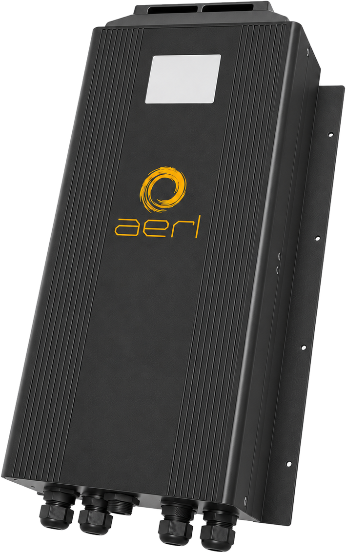
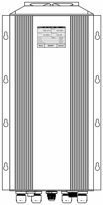
Figure 4.1 CoolMax SRX MV 300
Legacy product
The CoolMax SRX MV 300 is no longer manufactured. This manual is re-issued for systems already installed. For a new 48 V system, see the CoolMax SRX 600/70-48 at aerl.com.au, or contact AERL.
The CoolMax SRX MV 300 is an Australian engineered MPPT solar charge controller for 24 V and 48 V battery systems. It charges the battery efficiently and with a battery-specific charge profile, while making full use of the PV array.
4.1Features
CoolMax charge controllers use maximum power point tracking (MPPT) to draw the maximum power available from the PV array.
Peak conversion efficiency 98.3%
Low-heat thermal design, designed for long-term reliability
PV input up to 300 V open-circuit voltage
Built-in overload and thermal protection
Common-positive wiring
Master/slave operation
Touch-screen configuration
Multi-stage battery charging
4.2Firmware
This manual covers CoolMax SRX control firmware v4.08 and later and interface firmware v3.0 and later. For firmware updates, contact AERL support.
05
InstallationStandards and requirements, grounding, ground fault detection
Important
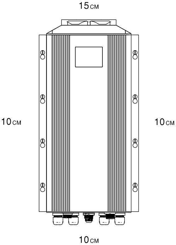
Install the CoolMax SRX in a clean, dry location away from direct sunlight. It cools best when mounted vertically. Keep at least 15 cm clear above the controller for air flow.
Caution — equipment damage
Do not connect a CoolMax SRX in parallel with third-party charge controllers. Doing so voids the warranty.
5.1Standards and Requirements
All installations must comply with national and local electrical standards and codes of practice. AERL recommends professional installation.
5.2Grounding
AERL charge controllers are designed to be installed in floating systems, but have provision for positive functional earthing for telecommunications applications if required.
Caution — hazard
DO NOT FUNCTIONALLY EARTH THE ARRAY if a negative earth is used for the batteries, load or DC system.
Important
The CoolMax ground (inside the enclosure) is marked with the protective earth symbol.
Caution — hazard
If the controller is damaged or malfunctioning, it may only be disassembled and repaired by a qualified service centre. Contact your installer or AERL. Incorrect reassembly risks malfunction, electric shock or fire.
5.3Ground Fault Detection
Important
Since 11 July 2015, solar PV installations in Australia and New Zealand have required an earth fault alarm on power conversion equipment (PCE), which includes solar charge controllers such as the CoolMax SRX (AS/NZS 5033:2014, clause 3.4.3, the edition current when this product was sold). Check the current edition of AS/NZS 5033 and local requirements for your installation.
Under AS/NZS 5033:2014 clause 3.4.3:
In systems where the PV array operates at LV, an earth fault alarm system shall be installed which, on an earth fault, causes an action to be initiated to correct the earth fault.
The alarm system is to repeat its operation at least hourly until the earth fault is corrected.
The alarm may be an audible signal or a visual indicator placed where operating staff or system owners will be aware of it, or another form of fault communication (for example email or SMS) shall be used to inform the system operator.
The system owner shall be given operating instructions that include the actions to take when the alarm operates.
Operating voltage below 120 Vdc. Equipment operated at ELV is not subject to AS/NZS 5033:2014 clause 3.4.3 and does not need a ground fault circuit or remote ground fault indicator.
Operating voltage 120 Vdc or higher. An external ground fault protection kit and a remote ground fault alarm are required. Recommended solutions are below.
Multiple controllers. When two or more charge controllers are installed on the same battery bank, disable all but one ground protection circuit. Only one ground fault indicator is required.
5.4Ground Fault Detection and Interruption Solutions
Negative grounded
Positive grounded
Floating
Ground fault protection circuit
AERL GFDI device, part no. AER-GFDI-N
AERL GFDI device, part no. AER-GFDI-P
AERL EarthGuard EG-600 (successor to the EG-300)
Remote ground fault indication (options)
System Information / Alarms screen; CoolMax Modbus RTU and CAN bus communications to external devices
System Information / Alarms screen; CoolMax Modbus RTU and CAN bus communications to external devices
EarthGuard alarm indication relay
The AER-GFDI-N and AER-GFDI-P kits were made for the CoolMax SRX 300; contact AERL for availability. Refer to the installation and operating manual of each device for installation and programming instructions.
5.5Mounting the Controller
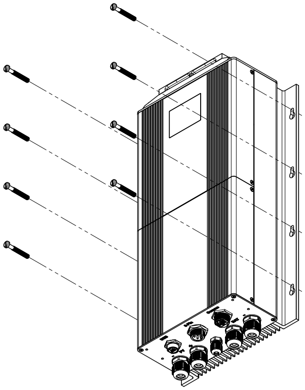
Fix the CoolMax SRX to a vertical surface with the M5 screws provided, through the eight mounting holes in the chassis flanges (Figure 5.1).
Figure 5.1 SRX MV 300 mounting hole locations
5.6Mounting Clearances
Keep the clearance zone in Figure 5.2 around the controller for cooling at full load: 15 cm above, and 10 cm to each side and below.
Figure 5.2 SRX MV 300 mounting clearances
5.7Wiring Information
Important
Wire sizes must comply with local and national standards. Input conductors and circuit breakers must be rated at 1.56 times the short-circuit current of the PV array.
Use copper wiring rated at 75 °C or higher.
SRX MV 300/50
The output current limit is 50 A.
Use at least #6 AWG (16 mm²) wire for the output between the controller and the battery bus bar or termination.
Fit a 63 A non-polarised DC circuit breaker between the controller output and the load. Recommended: NOARK Ex9BP 63 A 2-pole 300 Vdc circuit breaker.
Terminate both the input and output conductors with appropriately sized insulated crimp ferrules.
Torque all wire and ground terminals to 1.7 Nm (15 in-lb).
SRX MV 300/60
The output current limit is 60 A.
Use at least #4 AWG (25 mm²) wire for the output between the controller and the battery bus bar or termination.
Fit an 80 A non-polarised 2-pole DC circuit breaker, rated for at least 300 Vdc, between the controller output and the load. A 63 A breaker is too close to the 60 A output current and may trip in normal operation.
Terminate both the input and output conductors with appropriately sized insulated crimp ferrules.
Torque all wire and ground terminals to 1.7 Nm (15 in-lb).
Refer to the relevant IEC or AS/NZS wiring standard for PV array cable sizing, length and current-carrying capacity.
5.8Wiring Compartment
Caution — hazard
All wiring must enter the controller through the labelled cable glands in the base plate or the rear entry ports inside the enclosure. Never drill holes anywhere in the controller: metal swarf can enter the electronics and damage the unit once powered. Drilling any hole in the controller voids the warranty.
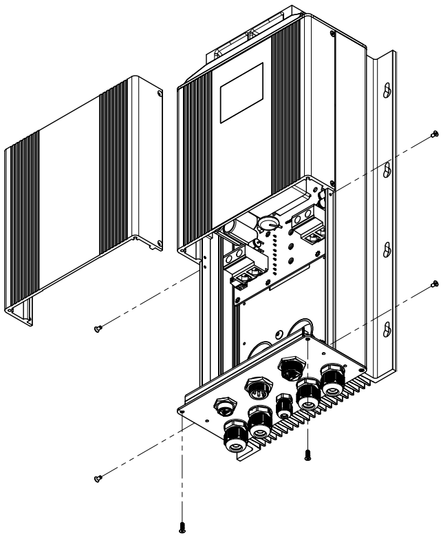
To install the cabling, remove the access panel: undo the two M4 countersunk Phillips screws on the bottom of the enclosure and the two M3 countersunk Phillips screws on each side of the access panel (Figure 5.3).
Figure 5.3 Access panel screw locations
5.9Wiring Polarity
Caution — equipment damage
Reversing the polarity of the input or output may damage the controller and voids the warranty. Confirm polarity with a multimeter before you close the input and output breakers.
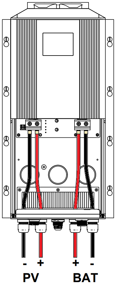
With the access panel removed, the input and output terminals are visible (Figure 5.4): PV input on the left, battery output on the right. If a ground fault device is fitted, its breaker sits between the input and output breakers.
OperationPowering up, programming the controller, battery charge profile
6.1Powering Up
The CoolMax SRX powers up when a PV or battery voltage is applied. The minimum voltage for start-up is 40 Vdc.
Close the PV breaker first.
Wait for the screen to start, then close the battery breaker.
Refit the access panel (the reverse of removal).
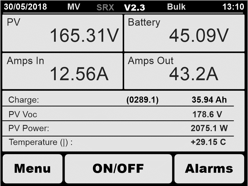
When the controller first powers up, the Real Time screen (Figure 6.1) appears. It shows live input and output measurements, the daily charge (and total charge in kWh), PV open-circuit voltage and PV power, and is the starting point for configuring the controller.
If battery temperature compensation is in use, (B) appears next to Temperature and the battery temperature is shown. Without a remote temperature sensor, (I) appears and the controller's internal core inductor temperature is shown.
Figure 6.1 Real Time telemetry screen
Power saving mode
After 30 minutes without a touch, the screen dims. Tap the screen to restore full brightness.
6.2Programming the Controller
The CoolMax SRX is configured from the touch screen on its front (Figure 6.2). The screen shows live measurements, the charge profile, and alarms, alerts and system information.
Figure 6.2 Touch screen location
6.3Battery Charge Profile
Important
The default charge profiles are for lead-acid batteries. The CoolMax SRX MV 300 charges to the set points in its charge profile. Other batteries, including some lithium batteries, can be used with a suitable charge profile. Contact AERL support to confirm compatibility before installation.
For safety, the charge output does not switch on by itself. Configure the charge profile for the battery before you enable the output.
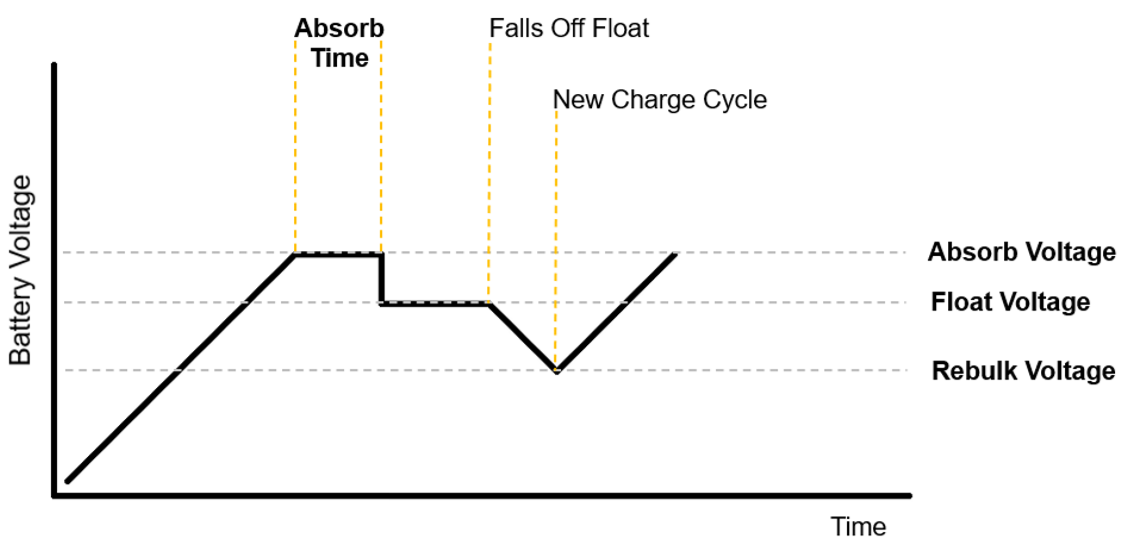
The controller uses a three-stage charge (Figure 6.3) and has preset charge voltages for each supported nominal battery voltage. Always check the battery manufacturer's charge voltages for the best battery life and performance; adjust them in the charge profile settings (Setting the Battery Charge Profile, below).
Figure 6.3 Battery charge profile: absorb, float and rebulk
Charge profile configuration
The charge profile sets the battery charge rate and the absorb, float and rebulk voltages. Equalisation is not supported.
Important
Equalisation is not supported on the CoolMax SRX. It is normally needed only for flooded lead-acid cells that have sulphated from poor charging. Equalisation is not required or recommended for LiFePO₄ or other lithium batteries, and is likely to damage them unless the battery manufacturer advises otherwise.
The default profile suits most applications; for the best profile for your battery, refer to its manufacturer's manual or datasheet. The SRX MV 300 default charge profile:
Setting
Default
Nominal battery voltage
48 V
Battery capacity
10 kWh
Setting
Default
Charge rate
1C
Absorb voltage
57.6 V
Absorb duration
120 minutes
Float voltage
55.2 V
Rebulk voltage
52.0 V
6.4Setting the Battery Charge Profile
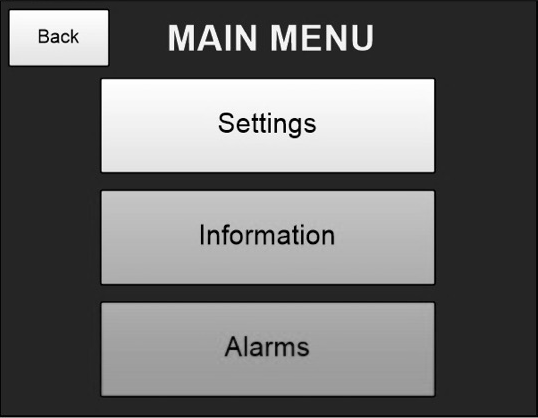
On the Real Time screen, tap Menu (bottom left).
On the MAIN MENU, tap Settings.
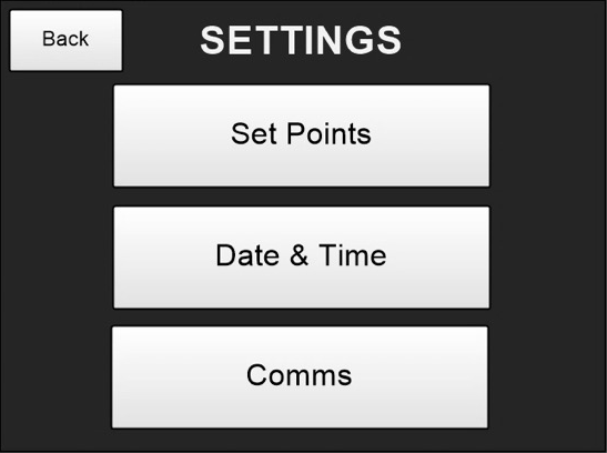
On the SETTINGS screen, tap Set Points.
Figure 6.4 Main menuFigure 6.5 Settings
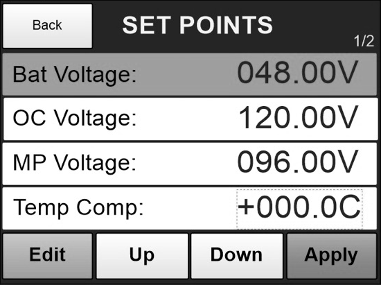
On the SET POINTS screen, the selected setting is highlighted. Tap Up or Down to move between settings and Edit to change the selected one.
Figure 6.6 Set points (page 1 of 2)
Important
There are two pages of charge profile settings (1/2 and 2/2). Selecting the nominal battery voltage and tapping Next fills the second page with the default profile for that voltage.
Caution — equipment damage
Set the charge profile to the battery manufacturer's recommendations. The default profile may not suit your battery; a wrong profile may damage the battery or shorten its life.
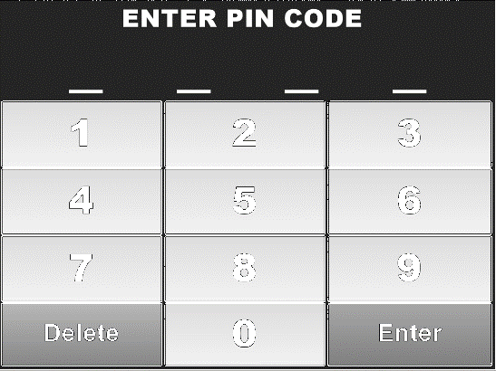
Enter the PIN to edit the setting (default 1111).
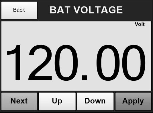
Adjust the value with Up and Down, then tap Apply.
Figure 6.7 PIN entryFigure 6.8 Editing a value
Save the charge profile by tapping Apply on the SET POINTS screen. The controller saves the settings and restarts.
Important
If a set point is outside the allowed limits for the nominal battery voltage, a warning appears and the profile cannot be saved. If you leave without tapping Apply, the new profile is not saved and you must enter it again.
6.5Enabling the Output
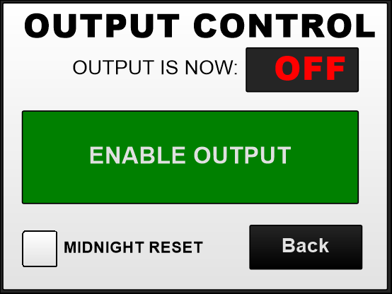
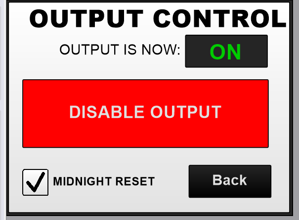
On the Real Time screen, tap ON/OFF to open the OUTPUT CONTROL screen, then tap Enable Output. Leave Midnight Reset ticked. After a few seconds the screen shows OUTPUT IS NOW: ON.
Once the output has been enabled, the controller remembers the output state through a loss of power.
6.6Setting the Time and Date
On the Real Time screen, tap Menu, then Settings, then Date & Time.
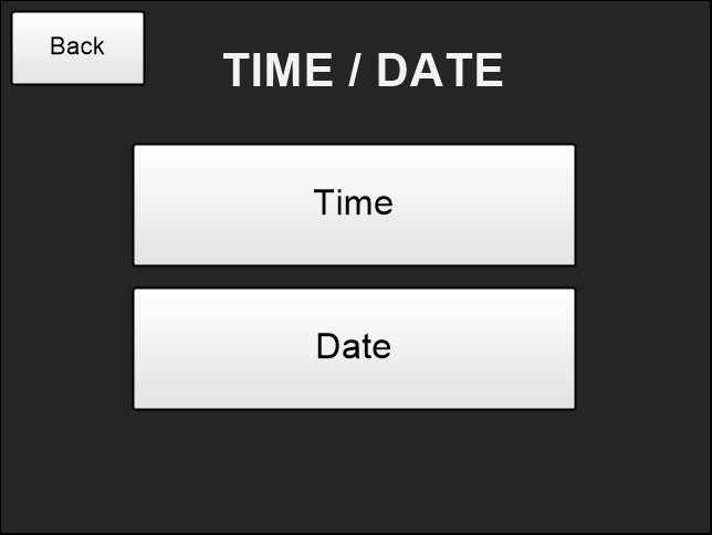
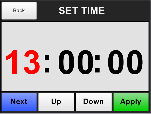
On the TIME / DATE screen, tap Time. Tap Next to move between digits and Up / Down to change them, then tap Apply. The TIME / DATE screen returns.
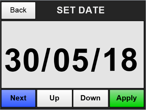
Tap Date and set it the same way, then tap Apply.
Figure 6.11 Time / dateFigure 6.12 Set timeFigure 6.13 Set date
6.7Battery Temperature Compensation
Important
Temperature compensation needs the AERL CoolMax SRX remote temperature sensor, part number SRX-RTS.
Temperature compensation measures the battery temperature and adjusts the absorb and float voltages to suit it. The controller adjusts its voltages by the factor set in the charge profile (Temp Comp, in mV/°C). The factor is per bank, not per cell.
Connecting the temperature sensor
Important
Set a temperature compensation value in the charge profile; the controller does not use the sensor until one is set.
Plug the sensor into the RJ45 port labelled RTS on the communications module at the base of the controller. Check the connector's orientation and do not force it; it clicks into place.
Sensor location
Place the sensor close to the battery cells, preferably centrally near the top of the bank.
Caution — equipment damage
Do not place the sensor where it may be exposed to water, moisture, direct sunlight or chemicals.
6.8Relay Alarms and Generator Control
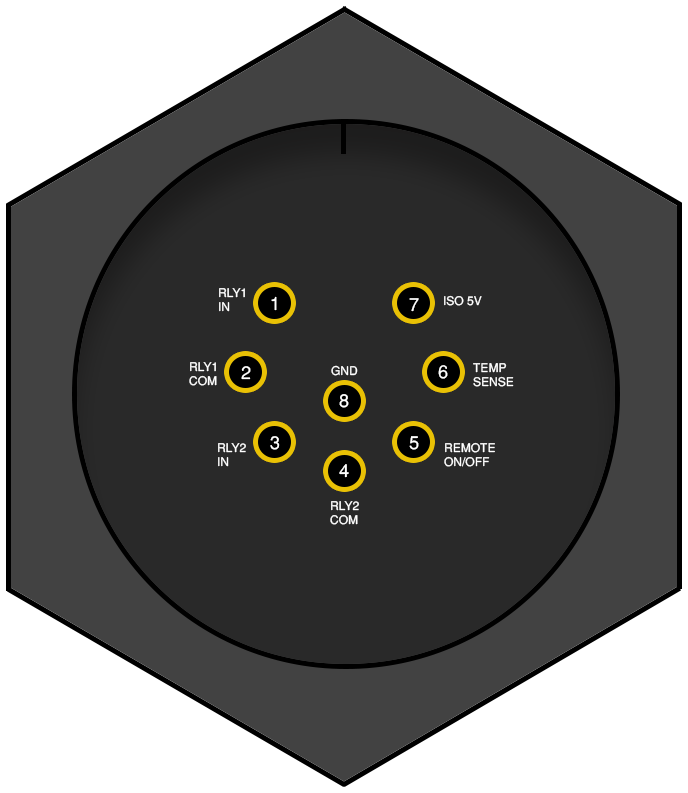
The CoolMax SRX has two relays for alarms and indication, rated 12 V / 1 A, on the 8-pin AUX connector (Figure 6.14).
Relay 1 (RLY 1), float indication. Closes when the battery bank reaches float. Use it to signal the battery's state of charge to a battery inverter.
Relay 2 (RLY 2), low battery voltage alarm. Commonly used to start a generator. Its settings are adjusted with the CoolMax Utility software (below).
Relay
NO
COM
RLY 1, float indication
Pin 1
Pin 2
RLY 2, low battery voltage alarm
Pin 3
Pin 4
When a relay activates, its contacts close. When it deactivates, the contacts are fully open, so an external alarm or generator control circuit can sense whether the relay is open or closed.
Figure 6.14 8-pin AUX connector: 1 RLY1 IN, 2 RLY1 COM, 3 RLY2 IN, 4 RLY2 COM, 5 remote on/off, 6 temperature sense, 7 isolated 5 V, 8 GND
Pins 5 to 8 carry remote on/off, temperature sense, isolated 5 V and ground. Contact AERL support before using them.
6.9CoolMax Utility Software
The CoolMax Utility (Windows) adjusts settings that are not on the touch screen, including the RLY 2 low battery voltage alarm. Download the CoolMax SRX 300 Utility from the documentation library at aerl.com.au.
Run Comms_Drivers_Setup (Install this first) to install the FTDI USB drivers.
Connect the PC to the controller's USB Mini-B port.
Run Coolmax.exe from the CoolMax Utility V1 folder.
6.10Communications
The CoolMax SRX supports CAN bus and Modbus RTU (RS485) for remote monitoring and control. Both are on the RJ45 comms socket at the bottom of the controller. The register and message maps are in the CoolMax SRX 300 Series Modbus and CAN Communications Protocol, at aerl.com.au.
Pin
Signal
1
+12 V (CAN)
2
+12 V (Modbus)
3
CAN-L
4
RS485-A
5
CAN-H
Pin
Signal
6
RS485-B
7
Not connected
8
Isolated GND
Master/slave operation
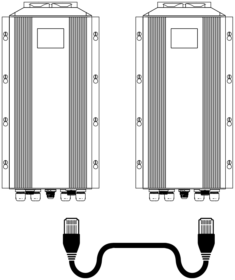
Two or more controllers can run as master and slave, linked by a patch cable between their comms sockets (Figure 6.15). Contact AERL support to set up master/slave operation.
Figure 6.15 Master/slave connection between two controllers07
TroubleshootingWarning codes, fault codes
When the CoolMax SRX detects a warning or fault, it raises an alarm in Alarms on the Real Time screen. Warning codes start with W and fault codes with F.
7.1Warning Codes
Code
Warning
Description
W001
Low input voltage detected
The PV input voltage is not high enough for the selected battery voltage.
W002
Temperature sensor not detected
The temperature sensor is unplugged or faulty.
W003
Low genset voltage detected
Low voltage detected on the genset line.
W004
Datalog full
The internal datalog is full and can no longer log data.
W005
PV array not detected
The PV array is not detected.
W006
Set points out of bounds
The set point configuration is outside its limits and may be dangerous for the selected nominal battery voltage.
7.2Fault Codes
Code
Fault
Description
F001
Low output voltage detected
Low output voltage detected. Confirm the battery is connected to the controller.
F002
High output voltage detected
High output voltage detected.
F003
High output current detected
High output current detected.
F004
Reserved
Reserved.
F005
High discharge current detected
The battery bank is discharging at an abnormally high rate.
F006
High battery temperature detected
The battery temperature sensor has detected a high battery temperature. Operating the battery at a high temperature greatly reduces its life.
F007
Input breaker open
The PV input breaker is open.
F008
Output breaker open
The battery output breaker is open.
F009
System power overload
System power overload.
F010
Negative PV current detected
Negative PV current detected. The controller has shut down to prevent damage.
Code
Fault
Description
F011
High PV current critical
High PV input current detected. The controller has shut down to prevent damage.
F012
High PV voltage critical
High PV voltage detected. The controller has shut down to prevent damage.
F013
High output current critical
High output current detected. The controller has shut down to prevent damage.
F014
Output voltage out of range
The battery voltage is outside the operating range for the selected nominal battery voltage (upper limit: absorb voltage + 3 V; lower limit: absorb voltage ÷ 1.4). Check the nominal voltage set point.
F015
Active cooling failure
The controller has detected a fault in its active cooling. Contact AERL for help or a replacement fan module.
F016
Internal temperature critical
The controller's internal temperature has reached a critical level and it has shut down to prevent damage.
If your situation is not covered here, contact AERL support on 1800 950 865 or at [email protected].
Australian Energy Research Laboratories
Address
1/75 Bluestone Circuit Seventeen Mile Rocks QLD 4073 Australia
 Download PDF· Rev 10.0
Installation and Operation User Manual