Rev 2.2.3 gives the first firmware release for every message, command and flag, back to 2.0.1. Working from an earlier revision, re-check remote frames (§2), master IDs and ID assignment (§3), the Active Flags and Inhibit Reason (§5.1), Shutdown recovery (§6.3), Power Target clamping (§6.4) and the battery BMS frames (§7).
Chapter 01
Network Topology & Pinout
Scope. This document is for integrating a master controller with the CoolMax SRX and compatible SRX-family slaves over CAN: topology, pinout, identifier format, and every broadcast and command frame the slave emits or accepts.
Firmware. Applies to CoolMax SRX and SRX-R firmware 2.0.1 and later. The Min FW column (or tag) gives the first release with each item. Releases 2.6.9 and 2.8.4 were for the SRX-R only, so an item they introduced reads 2.8.4 (SRX-R) / 2.9.4 (SRX), shortened to 2.8.4 R / 2.9.4 in narrow tables. Releases 2.6.6 to 2.8.4 have been withdrawn; update units on them to 2.17.9.
The CAN bus is structured as a linear network, with short stubs branching from ‘T’ connectors on the main bus backbone to each device. The CAN bus data lines must be terminated at each end of the main bus with 120 Ω resistors between the CAN-H and CAN-L signals.
SRX CAN Pin-Out
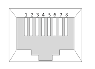
Pin-out is shown on an 8-position modular (RJ-style) connector with pins numbered 1–8 from left to right. The SRX presents two paralleled CAN sockets so units can be daisy-chained; both carry the same four signals.
Pin
CAN connector
3
+5 V
4
CAN High (CAN-H, non-inverting)
5
CAN Low (CAN-L, inverting)
6
GND
Pins 1, 2, 7 and 8 are unused. RS485 (Modbus) has its own pair of sockets, labelled MODBUS, with a different pin-out: pin 6 is RS485-B there, not GND. Do not plug a CAN cable into a MODBUS socket.
Figure 1 · RJ-style connector pin numbering
Isolation: pins 3 and 6 bring the SRX’s internal +5 V rail and signal ground out on the connector. If the bus crosses an isolation barrier, do not carry pins 3 and 6 through it.
CoolMax SRX
CAN ProtocolRev 2.2.316 November 2026
Chapter 02
Hardware & Software Overview
Hardware
The CAN hardware interface used is compatible with the CAN 2.0B standard. Three bit rates are selectable:
Default500 kbps
2.8.4 R / 2.9.4250 kbps
2.8.4 R / 2.9.4125 kbps
500 kbps is available on every release from 2.0.1. 250 and 125 kbps need 2.8.4 (SRX-R) / 2.9.4 (SRX); earlier releases run at 500 kbps only.
Software
The CAN protocol uses data frames for all communication. The SRX transmits standard (11-bit) data frames only and ignores every extended-identifier frame on the bus. Do not send remote frames. All measurement data is transmitted using 32-bit integers with the most significant byte (MSB) sent first.
CAN data frame
The protocol uses the standard CAN 2.0B data frame layout: 11-bit identifier (see §3), DLC, and up to 8 bytes of payload. The SRX populates each payload as one or two 32-bit integers, or as individually addressed bytes, as detailed per-message in §4–§6.
Chapter 03
Identifier, Addressing & Data Field
Identifier
The identifier field has been split into two sections for the CoolMax SRX. Bits 10–5 contain the device identifier and bits 4–0 contain the message identifier associated with that device.
Role
Device ID range
Min FW
MASTER ID
0 to 8
2.0.2 (see §3 below)
RESERVED
9
2.19.5
OPERATIONAL SLAVE ID
10 to 60
2.0.1
UNASSIGNED SLAVE ID (START-UP)
62
2.0.1 (nothing is sent on it)
CAN device IDs (6 bits)
CoolMax SRX
CAN ProtocolRev 2.2.316 November 2026
Use master IDs 0 to 8
Give a master a device ID from 0 to 8. Firmware 2.0.2 to 2.17.9 accepts commands from IDs 0 to 9; from 2.19.5 ID 9 is reserved and a master on ID 9 has its commands ignored. 2.0.1 accepts commands from any identifier, so a battery’s Pylontech-style frames can be taken as commands: update 2.0.1 units before they share a bus with a battery.
From 2.0.2, a slave only acts on a command whose device identifier is in the master range. Units also exchange coordination frames with each other; a master does not need to act on them.
Device ID Assignment
Units ship configured to CAN ID 10. Where several units share a bus, each one self-assigns a free identifier in the range 10 to 60 (2.0.1). From 2.4.2 a unit reuses its stored identifier across restarts; 2.0.x self-assigns on every start. From 2.19.6 self-assignment skips 24 and 56, whose frames would alias battery identifiers. A unit that has not yet settled on an identifier transmits nothing.
A rack powering up together takes a few seconds to settle. Do not treat identifiers as stable addresses across a re-index; key on the serial number in §4.1 instead.
Data Field
The data field in all frames is fixed at 8 bytes (64 bits), with the following exceptions:
Enable (§6.1) and Reset (§6.2) carry no data (DLC 0).
Shutdown (§6.3) accepts DLC 0 or 8 bytes.
The data field is sent and received in MSB-first order. Two messages are exceptions and are packed little-endian; both are called out where they are defined: Hardware Information (§4.5) and Remote Temperature (§6.6).
CoolMax SRX
CAN ProtocolRev 2.2.316 November 2026
Chapter 04
Broadcast Messages — Telemetry
Data frames containing telemetry values are periodically broadcast onto the bus by the CoolMax SRX slave. Unless noted, the message ID is the slave’s base address plus the offset shown.
Message
ID offset
Period
Min FW
Identification Information (§4.1)
Slave base + 0
2 s (3 s on 2.0.x)
2.0.1
PV Voltage / Current (§4.2)
Slave base + 1
1 s
2.0.1
Output Voltage / Current (§4.3)
Slave base + 2
1 s
2.0.1
Output Power / Device Temperature (§4.4)
Slave base + 4
1 s
2.0.1
Active Flags (§5.1)
Slave base + 5
1 s
2.0.1 (byte 3: 2.19.5)
General ACK (§5.3)
Slave base + 6
on demand
2.8.4 (SRX-R) / 2.9.4 (SRX)
Hardware Information (§4.5)
Slave base + 10
2 s
2.0.1
Firmware Version (§4.6)
Slave base + 11
2 s
2.0.1
GF Status (§5.4)
Master base + 12
500 ms, during a GF test only
2.0.2
Charge State (§5.2)
Slave base + 14
30 s
2.8.4 (SRX-R) / 2.9.4 (SRX)
CoolMax SRX
CAN ProtocolRev 2.2.316 November 2026
Broadcast Messages — Telemetry
§4.1
Identification information
Slave Base + 0Min FW 2.0.1DLC 8
Variable
Bits
Type
Description
Serial Number
63…32
Uint32
Device serial number, allocated at manufacture.
Device Status
31…0
Uint32
See enum below.
Device Status enum values:
Value
Name
Description
Min FW
0
Slave Un-Assigned
No operational ID yet.
2.0.1
1
Starting
Startup / initialisation in progress.
2.19.5
2
Output Enabled
Converter output is actively enabled.
2.0.1
3
Restricted
Thermal derating or other power limitation active.
2.19.5
4
Output Disabled
Converter output has been explicitly disabled.
2.0.1
5
Standby
Ready but not outputting.
2.19.5
6
Fault Detected
A fault has shut the converter down.
2.0.1
7
Minimum Power Idle
Demand below the minimum the unit can deliver. Benign: a full battery or low irradiance.
2.19.5
8
Output Unreachable
The unit could not settle at a usable operating point. Check load and configuration.
2.19.5
Decode any unrecognised value as “ready, not outputting”: new codes may be added.
§4.2
PV voltage / current measurement
Slave Base + 1Min FW 2.0.1DLC 8
Variable
Bits
Type
Description
PV Current
63…32
Int32
PV Current (mA)
PV Voltage
31…0
Int32
PV Voltage (mV)
CoolMax SRX
CAN ProtocolRev 2.2.316 November 2026
Broadcast Messages — Telemetry (Cont.)
§4.3
Output voltage / current measurement
Slave Base + 2Min FW 2.0.1DLC 8
Variable
Bits
Type
Description
Output Current
63…32
Int32
Output Current (mA)
Output Voltage
31…0
Int32
Output Voltage (mV)
§4.4
Output power / device temperature measurement
Slave Base + 4Min FW 2.0.1DLC 8
Variable
Bits
Type
Description
Device Temperature
63…32
Int32
Heatsink temperature, millidegrees Celsius
Output Power
31…0
Int32
Output Power (W)
Output power is derived from the output voltage and current in §4.3 and reads 0 whenever either of them is at or below zero. It is output power, not input power.
§4.5
Hardware information
Slave Base + 10Min FW 2.0.1DLC 8
This frame is little-endian. Unlike every other broadcast, its three fields are sent least significant byte first.
Bytes
Field
Type
Description
0–1
Hardware Revision
Uint16 LE
Control board hardware revision.
2–5
Manufacture Date/Time
Uint32 LE
Manufacture date and time stamp.
6–7
Check Value
Uint16 LE
Check value. Ignore.
Corrected in Rev 2.2.0: earlier revisions described this frame as [HW Rev][Batch][Manufacturer][Device Type], four Int16 values MSB-first. Batch ID, Manufacturer ID and Device Type are not available over CAN; read them over Modbus RTU or through AERL Link.
§4.6
Firmware version
Slave Base + 11Min FW 2.0.1DLC 8
Bytes
Field
Type
Description
0–3
Reserved
—
Ignore these bytes.
4
Major
Uint8
Firmware major version.
5
Minor
Uint8
Firmware minor version.
6
Patch
Uint8
Firmware patch version.
7
Reserved
Uint8
Reserved, 0.
CoolMax SRX
CAN ProtocolRev 2.2.316 November 2026
Chapter 05
Broadcast Messages — Status
§5.1
Active flags — faults
Slave Base + 5Min FW 2.0.1DLC 8
Bytes
Field
Type
Description
0–2
Reserved
—
Ignore (not zero-filled on 2.17.9 and earlier).
3
Inhibit Reason
Uint8
§5.1.1. From 2.19.5; ignore it before.
4–7
Fault Flags
Uint32
Bit field, MSB-first. Bit 0 is the LSB of byte 7.
Bit
Flag
Description
Min FW
0
Hardware Fault (Generic)
Generic hardware fault; battery BMS alarm (§7)
2.0.1
1
No Config Data
No configuration data set
2.0.1
2
Config Data Out of Range
Configuration out of range; BMS limit (§7) from 2.19.5
2.0.1
3
Battery Sense Lost
Battery Sense no longer responding
2.0.1
4
CAN Master Lost
CAN master lost (Note 1)
2.0.1
5
Internal Over Temp
Internal temperature fault
2.0.1
6
Vin Low Fault
Input voltage too low
2.0.1
7
Vout Low Fault
Output voltage too low
2.0.1
8
Vout High Fault
Output voltage too high
2.0.1
9
Vin High Fault
Input voltage too high
2.0.1
10
High PV Current
PV input current too high
2.0.1
11
Over Temp Fault
Device temperature exceeds maximum
2.0.1
12
Low Battery Temp
Low battery temperature
2.0.1
13
Earth Fault Positive
Earth fault on positive conductor
2.0.1
14
Earth Fault Negative
Earth fault on negative conductor
2.0.1
15
Active Cooling Fault
Fan fault
2.0.1
Bit
Flag
Description
Min FW
16
Output Over-current
Output over-current; on bit 24 from 2.19.5
2.0.1
17
Iin High Fault
Input current too high
2.0.1
18
Cross Check Fault
Cross-check failed
2.0.1
19
Temp Sensor Timeout
Temperature sensor unresponsive
2.0.1
20
Earth Fault
Low isolation resistance (see below)
2.0.1
21
No Output Fault
No output detected
2.0.1
22
Low Bat Temp Cut-off
Low battery temperature cut-off active
2.0.1
23
High Bat Temp Cut-off
High battery temperature cut-off active
2.0.1
24
Current Flow Disrupted
Charging interrupted (see below)
2.0.1
25
Pre-charge Failure
Pre-charge failure
2.0.1
26
PV Pre-charge Failure
PV input pre-charge failure
2.8.4 R / 2.9.4
27
PWM Regulation Failure
Current flowing while PWM is disabled
2.19.5
28
PWM Corruption
PWM state corruption detected
2.19.5
29
Stack Overflow
Internal stack overflow detected
2.19.5
30
Clock Failure
Clock failure (CSS/drift) detected
2.19.5
31
Brownout
Brown-out detected
2.19.5
2.8.4 R / 2.9.4 is 2.8.4 on the SRX-R and 2.9.4 on the SRX. Bit 16: output over-current before 2.19.5; from 2.19.5 it reports on bit 24 instead. Bit 20: clears itself after about 30 min from 2.6.6; held until the unit resets from 2.19.6. On 2.17.9 and earlier the flags are a latched snapshot, updated when a fault is raised or cleared. Some bits cover more than one underlying condition. Use AERL Link or the unit’s event log to identify the specific cause, or contact AERL.
CoolMax SRX
CAN ProtocolRev 2.2.316 November 2026
§5.1.1
Inhibit reason (byte 3)
Min FW 2.19.5
Undefined before 2.19.5: ignore it. From 2.19.5 byte 3 names why a healthy unit is deliberately delivering no output, so it can be told apart from an idle unit.
Value
Name
Clears on
Min FW
0
None
—
2.19.5
1
Shutdown Latch
Latched off by a fault elsewhere on the bus. Reset or power cycle.
2.19.5
2
Input Protection Lockout
Reset or power cycle.
2.19.5
3
Version Gate
Every unit on the bus on 2.19.6 or later. A unit holds off while it hears older firmware: update the whole bus.
2.19.6
4
BMS Envelope
Charge target back inside the battery’s limits (§7).
2.19.5
5
Isolation Lockout
Reset or power cycle.
2.19.5
§5.2
Charge state
Slave Base + 14Min FW 2.8.4 R / 2.9.4DLC 8
Bytes
Field
Type
Description
0–5
Reserved
—
Reserved, zero-filled.
6
Reserved
Uint8
Advisory status flags. Do not parse.
7
Charge State
Uint8
0 = Bulk · 1 = Absorb · 2 = Equalise · 3 = Float
Do not read bytes 4–7 as a single Int32. Byte 6 is zero before 2.19.5 and carries flag bits from 2.19.5, so a 32-bit read of that field returns, for example, 0x0303 instead of 3. Read byte 7 alone.
§5.3
General ACK broadcast
Slave Base + 6Min FW 2.8.4 R / 2.9.4DLC 8
Variable
Bits
Type
Acknowledged
63…56
Uint8
Reserved
55…0
—
1 = Acknowledged, 0 = Not Acknowledged (data byte 0); reserved bits zero-filled. Sent only in reply to Change State (§6.5).
Not acknowledged: Enable, Reset, Shutdown and Power Target. Confirm those from the telemetry.
§5.4
GF status broadcast
Master Base + 12DLC 8Min FW 2.0.2
Variable
Bits
Type
Reserved
63…0
—
Broadcast every 500 ms while a ground-fault test is in progress, to signal that a GF test is active.
Note: sent with the Master base address, not the slave’s own. Subscribe on the master ID range. The frame carries no source identity.
CoolMax SRX
CAN ProtocolRev 2.2.316 November 2026
Chapter 06
Command Messages
Commands are sent by the master, at the master’s base address plus the offset shown. From 2.0.2 a slave acts only on commands from the master range (use 0 to 8; §3).
Command
ID offset
DLC
ACK
Min FW
Enable (§6.1)
+22
0
no
2.0.1
Reset (§6.2)
+23
0
no
2.4.2
Shutdown (§6.3)
+24
0 or 8
no
2.0.1
Power Target (§6.4)
+25
8
no
2.0.1 (clamping: see §6.4)
Change State (§6.5)
+30
8
yes
2.8.4 (SRX-R) / 2.9.4 (SRX)
Remote Temperature (§6.6)
+31
8
no
2.0.1
GF Status Hold (§6.7)
+12
8
no
2.0.2
§6.1
Enable
ID Master Base + 22DLC 0Min FW 2.0.1
Enables the output. A valid Power Target (§6.4) must have been received first: Enable is ignored by a unit that has never had a target, or whose target has timed out (Note 1). Send the target, then the enable.
§6.2
Reset
ID Master Base + 23DLC 0Min FW 2.4.2
Restarts the module, staggered by serial number so units on a shared bus do not reboot together; allow a few seconds. On 2.0.1 to 2.0.3, Reset does not work as described: update those units first.
§6.3
Shutdown
Master Base + 24DLC 0 or 8Min FW 2.0.1
Disables the output of the charger. Send DLC 0, or 8 bytes with byte 0 = 0x00. This is a recoverable stop: the unit disables its output and stays off until it receives Enable (§6.1). A Power Target alone does not restart it. A unit reporting Inhibit Reason 1 (§5.1.1; 2.19.5) has been latched off by a fault elsewhere on the bus: reset or power-cycle it.
§6.4
Power target
Master Base + 25DLC 8Min FW 2.0.1
Variable
Bits
Type
Description
Voltage
63…32
Uint32
Output Voltage Target (mV), e.g. 57600
Current
31…0
Uint32
Maximum Output Current (mA), e.g. 70000
Not acknowledged. At most one target is accepted every 250 ms (100 ms before 2.4.2); targets sent faster than that are discarded.
From 2.8.4 (SRX-R) / 2.9.4 (SRX), targets are clamped: current to the configured limit; voltage only above the configured absorb (or equalise) voltage + 5 V; a low non-zero target is raised to the minimum. If the unit regulates below the commanded value, check its configured set points before treating it as a fault. Earlier releases reject an out-of-range target (event −1302) and disable the output.
CoolMax SRX
CAN ProtocolRev 2.2.316 November 2026
§6.5
Change state
Master Base + 30DLC 8Min FW 2.8.4 R / 2.9.4
Variable
Bits
Type
State
63…56
Uint8
Reserved
55…0
—
State (data byte 0): 0 = Bulk · 1 = Absorb · 2 = Equalise · 3 = Float. Acknowledged with §5.3. A request for Equalise is rejected with a NACK when equalisation is disabled in the unit’s charge configuration; any value above 3 is also NACKed.
§6.6
Remote temperature
Master Base + 31DLC 8Min FW 2.0.1
Variable
Bits
Type
Battery Temperature
63…32
Int32 LE
Reserved
31…0
—
Battery temperature in millidegrees Celsius (°C × 1000), packed in data bytes 0–3 little-endian. Bytes 4–7 are ignored entirely. Values outside −10 to 100 °C are ignored. Used for temperature-compensated charging. Not acknowledged.
§6.7
GF status hold
Master Base + 12DLC 8Min FW 2.0.2
Sent by a device about to perform a ground fault test, so units sharing the array hold their startup until the test finishes. Payload ignored. Same message identifier as the GF Status broadcast (§5.4): the SRX treats the frame as a command when it arrives from a master identifier and as telemetry otherwise. Not acknowledged.
§6.8
Reserved message identifiers
All other message identifiers are reserved. Do not transmit them on a bus carrying SRX units, and ignore any frame seen on them.
Chapter 07
Battery BMS Frames Consumed by the SRX
Where an SRX shares a CAN bus with a battery that publishes the Pylontech-style frame set, it listens to the frames below. No configuration is required.
ID
Use
Min FW
0x359
Alarm flags. A high voltage, high temperature, high charge current, BMS internal or cell imbalance alarm stops charging. Logged as event −1305.
2.4.2
0x351
Charge voltage limit and charge current limit, both in 0.1 unit steps, little-endian. Used as a ceiling to cross-check the SRX’s own charge target.
2.19.5
On firmware 2.17.9 and earlier the SRX charges to its own configuration and ignores 0x351 and 0x356. From 2.19.5, if the SRX’s charge target stays outside the limits published on 0x351, the unit stops and raises fault flag bit 2 with Inhibit Reason 4 (§5.1.1), and resumes when the target is back inside the published envelope.
Releases 2.0.1 to 2.6.7 transmit frames on 0x305 and 0x307 every 2 s (vendor identification), which can conflict with a battery that uses those identifiers. 2.6.9 (SRX-R), 2.9.4 (SRX) and later do not transmit them.
CoolMax SRX
CAN ProtocolRev 2.2.316 November 2026
Implementation Notes
Note 1 · Keep-alive
Under a CAN master, the CoolMax slave must receive a Power Target command at least every 32 seconds (the timeout is about 32–34 s). If it does not, it reverts to its own stored charge configuration and disables its output (2.0.1). This is the CAN Master Lost condition (bit 4). The next valid Power Target clears the condition and re-enables the output, provided no other fault is active. Send a target every 1 to 5 seconds in normal operation.
Note 2 · Auto-start
The CoolMax slave will automatically begin charging after receiving a valid voltage target from the master device, provided no fault flags are set. An explicit Enable (§6.1) is only needed after a Shutdown.
Note 3 · Bus loading
Keep the SRX on a bus segment with minimal unrelated traffic. Heavy third-party traffic costs the SRX processing time.
Revision History
Revision
Date
Change
Earlier revisions: see previous editions.
2.1.0
09/09/26
Corrected bit rates, master ID range (0–8, 9 reserved), Hardware Information, Firmware Version and Charge State layouts and the keep-alive interval. Added device status 7 and 8, the inhibit reason byte, Power Target clamping, the GF Status hold command, the reserved identifier list, the battery BMS frames and ID self-assignment.
2.2.0
10/09/26
Reorganised for integrators.
2.2.1
08/11/26
Updated for firmware 2.19.6: inhibit reason 3, flag notes, reserved identifiers, IDs 24 and 56; MODBUS sockets have their own pin-out; contents page corrected.
2.2.2
09/11/26
Minimum firmware marked on items that need firmware later than 2.17.9; device status 7 and 8 need later firmware.
2.2.3
16/11/26
Minimum firmware for every message, command and flag, from 2.0.1; corrections for firmware 2.17.9 and earlier; internal identifiers removed.
 CoolMax SRX