AudienceSystem designers, installers and integrators
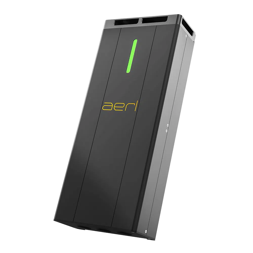
ControllersSRX and SRX-R, 48 V and 120 V
FormatA4 · 16 pages
About This Guide
This guide is for designing DC-coupled systems with CoolMax SRX and SRX-R charge controllers and a battery inverter that is not a Selectronic SP PRO: Victron Energy, Deye and other battery inverters. It covers the communication options, the PV array design, the battery charge profile and systems with several controllers. For the Selectronic SP PRO, the AERL documents named in chapter 03 apply.
Installation, wiring and settings are in the CoolMax SRX and SRX-R user manuals. The system design is the designer's responsibility: check it against AS/NZS 5033, AS/NZS 5139, AS/NZS 3000 and the inverter and battery manufacturers' requirements.
Victron Energy, Deye, Selectronic, SP PRO and other third-party names are trademarks of their respective owners. They are used here only to identify compatible equipment.
01
DC Coupling With the CoolMax SRXHow it works, the controllers
1.1How It Works
In a DC-coupled system the CoolMax SRX converts PV power straight to battery charge current. The battery inverter is a separate device on the same battery: it supplies the AC loads from the battery and can also charge it from the grid or a generator. The SRX and the inverter do not need to communicate for the system to work: each follows its own charge settings, and the battery is shared.
One type of charge controller
Do not connect CoolMax controllers in parallel with third-party charge controllers. Several SRX or SRX-R controllers can share a battery (chapter 06).
1.2The Controllers
Parameter
SRX 600/70-48
SRX-R 600/60-48
SRX 600/30-120
SRX-R 600/30-120
Format
Wall mount
2U rack module
Wall mount
2U rack module
Nominal battery voltage
24 V / 48 V
24 V / 48 V
120 V
120 V
Battery voltage range
18–30 Vdc / 40–60 Vdc
18–30 Vdc / 40–60 Vdc
90–170 Vdc
90–170 Vdc
Max. charge current
70 A
60 A
30 A
30 A
Nominal charge power
2016 W / 4032 W
1728 W / 3456 W
4320 W
4320 W
MPP voltage range (Vmp)
170–540 V
170–540 V
215–540 V
215–540 V
Min. PV voltage (MPPT)
100 V
100 V
200 V
200 V
Max. PV input voltage (Voc)
600 V
600 V
600 V
600 V
Max. PV input current (Imp)
18 A
18 A
18 A
18 A
Max. PV short-circuit current (Isc)
25 A
25 A
25 A
25 A
Max. PV array power
200% at 48 V, 130% at 24 V
200%
200%
200%
The SRX starts once the PV voltage is above 60 V and at least 10 V above the battery voltage. It does not power up from the battery.
02
Communication OptionsChoosing a mode, what the SRX does not do
2.1Choosing a Mode
Mode
What it does
Use it when
Standalone
The SRX charges to the profile set in AERL Link.
Any battery and inverter. The default for Victron, Deye and other inverters.
On the battery's CAN bus
The SRX charges to its own profile and also stops charging when the battery reports an alarm (Pylontech-style frames).
The battery publishes those frames and the bus can take the SRX (section 2.3).
Under a CAN master (EMS)
A controller sends the SRX its charge targets (Power Targets) over CAN.
An AERL Nexus with AERL's EMS firmware (Kakadu 120 systems), or a third-party controller written to the SRX CAN protocol (section 2.4).
Monitoring only
Read-only Modbus RTU over RS485, or AERL Cloud through a Nexus Gateway on the SRX CAN bus.
Any mode, to monitor the SRX.
2.2What the SRX Does Not Do
The SRX does not communicate with Victron (VE.Can, VE.Direct, DVCC), Deye or other third-party inverters. A Victron GX device does not see or control it.
It does not take its charge settings from the battery. It charges to its own configuration, set in AERL Link.
Its RS485 Modbus interface is read-only: it cannot be controlled over Modbus.
Because the inverter does not see the SRX, check how the inverter measures the battery's state of charge (chapter 03).
2.3On the Battery's CAN Bus
Where an SRX shares a CAN bus with a battery that publishes the Pylontech-style frame set, it listens for the battery's alarms (frame 0x359). A high voltage, high temperature, high charge current, BMS internal or cell imbalance alarm stops charging (fault −1305, Battery BMS fault). No configuration is needed and the SRX sends nothing in reply. It still charges to its own profile: set the profile within the battery manufacturer's charge settings (chapter 05).
The bus speed must match: the SRX runs at 500 kbps by default (250 and 125 kbps selectable). Keep the SRX on a bus segment with little unrelated traffic. Before you put an SRX on the CAN bus between a battery and a third-party inverter, check that the inverter's battery port accepts other devices on the bus: a Victron GX device's BMS-Can port, for example, is for the battery. If in doubt, run the SRX standalone and contact AERL.
2.4Under a CAN Master
A CAN master (an EMS) controls every SRX on the bus with Power Targets (a voltage target and a current limit). AERL's Nexus with EMS firmware does this in the Kakadu 120 system (Kakadu Commissioning Guide). A third-party controller must be written to the CoolMax SRX CAN Bus Communications protocol and the CoolMax SRX CAN Integration Guide, available from AERL on request: contact AERL before you design one.
AERL documents two ways to DC-couple the SRX with an SP PRO:
48 V systems: a current shunt (typically 100–200 A) in the SRX output feeds an SP PRO shunt input, so the SP PRO measures the solar charge current; the SP PRO's SOC resets to 100% on a voltage offset (SP PRO with CoolMax SRX Integration Guide; Selectronic DC Coupled Example System).
120 V systems with the Kakadu 120: the Nexus EMS directs the SRX (Kakadu Commissioning Guide).
3.2Victron Energy
The SRX runs standalone; the Victron inverter/charger and the battery are set up as Victron and the battery manufacturer instruct.
Managed battery (for example the LiFe² 5120S through a GX device): the GX device uses the battery's own SOC, so the solar current from the SRX is counted. The battery's charge limits control the Victron chargers only: set the SRX profile within the battery's charge settings (chapter 05).
Battery without communication: Victron's GX documentation says that DC chargers not integrated with the GX make the inverter/charger's SOC inaccurate, and that such systems need a dedicated battery monitor (BMV, SmartShunt or Lynx Shunt VE.Can). Fit one, so that the SRX's current is measured.
Do not use Victron solar charge controllers on the same battery as CoolMax controllers.
3.3Deye
The SRX runs standalone. With a managed battery in Lithium mode (for the LiFe² 5120S, Lithium Mode 00), the Deye takes the battery's SOC from its BMS, so the SRX's charge is counted. Set the SRX profile within the battery's charge settings.
3.4Other Battery Inverters
Any battery inverter that shares a battery with a charge controller can be DC-coupled with the SRX standalone, within the battery voltage range of the SRX model. Check that the inverter's SOC accounts for current it does not measure itself: a managed battery's own SOC, or a battery monitor in the battery circuit.
3.5Charge Voltages of Two Charge Sources
When the inverter also charges the battery (from the grid or a generator), its charge voltages and the SRX's must not work against each other. The rule AERL publishes for the SP PRO: decide which source has charging priority. If the system is mainly DC-coupled, set the inverter's charge voltages (absorb, float) 0.2 V below the SRX's; if it is mainly AC-charged, set the SRX's 0.2 V below the inverter's. For other inverters, apply the same principle within the battery manufacturer's limits, or contact AERL.
04
PV Array DesignLimits, string sizing, isolators, breakers and cables
4.1Limits
Limit
48 V models
120 V models
String Vmp at the hottest cell temperature
At least 170 V
At least 215 V
String Vmp at the coldest cell temperature
At most 540 V
At most 540 V
String Voc at the lowest cell temperature
At most 600 V
At most 600 V
Array Imp per controller
At most 18 A
At most 18 A
Array Isc per controller
At most 25 A
At most 25 A
Array power per controller
SRX: 8064 W at 48 V (200%), 2621 W at 24 V (130%). SRX-R: 6912 W at 48 V (200%)
8640 W (200%)
The array power limit is the controller's nominal charge power times its oversizing ratio. When the array delivers more than the nominal power, the controller limits its output.
4.2String Sizing
Maximum modules in series:Vmax = N × Voc × [1 + βVoc × (Tmin − 25 °C)] must not exceed 600 V, where βVoc is the module's (negative) Voc temperature coefficient and Tmin the lowest expected cell temperature (the site's record low). A string above 600 V on a cold morning stops the SRX (fault −1152, High PV voltage).
Minimum modules in series: the string's Vmp at the hottest expected cell temperature must stay above 170 V (48 V models) or 215 V (120 V models).
Parallel strings: the strings' combined Imp must not exceed 18 A and their combined Isc must not exceed 25 A. With most current modules this means one string per controller.
Each controller has its own array: never connect one string to two controllers.
4.3Isolators, Breakers and Cables
PV conductors, isolators and breakers: rated for at least 1.56 × the array's short-circuit current. For example, a 25 A PV isolator suits an array with an Isc of 16 A or less; for an Isc up to 25 A, fit an isolator of at least 40 A.
Copper wiring rated for 75 °C or more. Keep the voltage drop to 2% or less.
Output to the battery:
Controller
Output cable (minimum)
Output breaker (non-polarised DC)
SRX 600/70-48
16 mm² (#5 AWG)
80–125 A (Beny BDM-125 recommended)
SRX 600/30-120
16 mm² (#5 AWG)
40 A
SRX-R 600/60-48
50 mm² (1/0 AWG) per 2U shelf
160 A per shelf of two modules (Noark Ex9MD 160 A recommended)
SRX-R 600/30-120
16 mm² (#5 AWG)
40 A
4.4Example: SRX 600/70-48
An example module (use your module's own datasheet): 550 W, Voc 49.6 V, Vmp 41.6 V, Isc 14.0 A, Imp 13.2 A, βVoc −0.25%/°C, βPmax −0.35%/°C. Site record low −5 °C; hottest cell temperature 70 °C.
Check
Working
Voc at −5 °C, per module
49.6 × [1 + (−0.0025 × −30)] = 53.3 V
Maximum in series
600 ÷ 53.3 = 11.3, so up to 11 modules (586 V at −5 °C)
One string: Imp 13.2 A (limit 18 A), Isc 14.0 A (limit 25 A). A second string in parallel would exceed 25 A Isc.
Array power
11 × 550 W = 6050 W, within 8064 W (200% of 4032 W)
PV isolator
At least 1.56 × 14.0 A = 21.8 A: a 25 A isolator
The Vmp line uses the power coefficient as an estimate of the voltage coefficient; use the module's Vmp coefficient where its datasheet gives one.
05
Battery Charge ProfilesThe profile, profiles for shared batteries, lead-acid batteries
5.1The Profile
The SRX charges in three stages (constant current, then constant voltage: bulk, absorb, float). It does not charge until a profile is set for the connected battery. Set it in AERL Link (OUTPUT tab):
Setting
What it does
Battery charge rate
The SRX's maximum charge current
Absorb voltage and absorb time
The constant-voltage stage
Tail current
The current at which absorption ends
Float voltage
The voltage held once the battery is full
Re-bulk voltage
The voltage at which a new charge cycle starts
Equalisation
Only for flooded lead-acid batteries with sulfation. Not for LiFePO4 or other lithium batteries
Temperature compensation
Default 50 mV/°C. Needs a battery temperature, from an AERL Battery Sense
Low-temperature charge cutoff
Stops charging below a set temperature. Disabled by default; needs a battery temperature
The Battery Preset list holds AERL's recommended profiles for common batteries. The default profile suits a generic LiFePO4 battery. For any other battery, use the battery manufacturer's charge settings.
5.2Profiles for Shared Batteries
Charge voltage: the SRX's absorb and float voltages must not exceed the battery manufacturer's charge voltage. For the LiFe² 5120S that is 56 V (LiFe² PCE Integration Guide, §2.1).
Charge current: set each SRX's charge rate so that all charge sources together stay within the battery's charge current limit. For the LiFe² 5120S in Self-Managed operation that is 70 A per module; in Managed operation the battery's own limit (up to 100 A per module at 25 °C, less in the cold) also caps the inverter's charging.
5.3Lead-Acid Batteries
Lead-acid banks do not report their temperature: fit an AERL Battery Sense to the SRX's CAN port (with the SRX's CANBUS 5 V switch on). It gives the SRX the battery temperature and voltage for temperature compensation and the low-temperature cutoff.
06
Several ControllersSharing one battery, CAN bus, RS485 Modbus
6.1Sharing One Battery
Several SRX or SRX-R controllers can charge one battery. Each has its own PV array, its own PV isolator and its own output breaker to the battery bus. Set the same charge profile on every controller.
For SRX-R modules, the recommended setup in the SRX-R manual is two modules in one 2U shelf as the only charge controllers on the battery bus, with a 160 A breaker on the shelf output (48 V). For several shelves or mixed controllers, contact AERL.
6.2CAN Bus
Item
Rule
Topology
Daisy-chain the controllers through their two CANBUS sockets. A Nexus or a battery can sit on the same bus.
Termination
120 Ω at each end of the bus only. Each SRX and each SRX-R shelf has a CANBUS 120 Ω switch: on at an end of the bus, off in the middle. The Nexus has no built-in termination: at an end, fit a 120 Ω plug in its spare socket.
CAN IDs
Units ship at CAN ID 10. On a shared bus each unit takes a free ID from 10 to 60 automatically, skipping 24 and 56 (their frames would alias battery identifiers); 62 means not yet assigned. Identify units by serial number, not by ID.
Speed
Every device on the bus at the same speed: 500 kbps default. The Nexus runs only at 500 kbps.
6.3RS485 Modbus
Each SRX on a Modbus segment needs its own Modbus ID (1–90, default 20), and every device on the segment the same speed (9600 baud default). Daisy-chain the controllers through their MODBUS sockets, with the master at one end; terminate both ends with 120 Ω (the last SRX's termination switch on).
07
Worked ExamplesExample 1: Victron with a Managed LiFe² battery
The loads and module values in these examples are illustrative.
7.1Example 1: Victron With a Managed LiFe² Battery
A single-phase off-grid site: a Victron MultiPlus-II 48/5000/70-50 with a GX device, and LiFe² 5120S batteries in Managed mode (LiFe² Managed Battery Integration Guide, chapter 03). Two SRX 600/70-48 controllers, each with the 11-module string of chapter 04.
Item
Design
PV
2 × 6050 W = 12.1 kWp, one string per SRX
Charge current
SRX: up to 2 × 70 A = 140 A. MultiPlus-II charger: 70 A. Together 210 A
Battery
At least 3 LiFe² 5120S modules to take 210 A at 100 A per module (more for a cold site), and at least the MultiPlus-II's minimum (single-phase off-grid: 2). Energy decides the rest (LiFe² System Sizing Guide)
SRX mode
Standalone: profile set within the LiFe² 5120S charge voltage (56 V)
GX device
Battery monitor set to the LiFe² battery, so the GX uses the battery's SOC
Monitoring
An AERL Nexus on the two SRX controllers' CAN bus (SRX at one end with its 120 Ω switch on; Nexus at the other with a termination plug) for AERL Cloud
7.2Example 2: Deye With a Managed LiFe² Battery
A Deye SUN-8K-SG05LP1-EU with LiFe² 5120S batteries in Managed mode (Lithium Mode 00), and one SRX 600/70-48.
Item
Design
Battery
At least 3 modules (the SUN-8K-SG05LP1-EU minimum, LiFe² System Sizing Guide)
SRX mode
Standalone: profile within the LiFe² 5120S charge voltage (56 V); charge rate 70 A
Item
Design
Charge current
The SRX (up to 70 A) and the Deye's battery charging (its maximum charge current, from the Deye datasheet) can charge at the same time: together they must stay within the battery's limit, 3 × 100 A = 300 A at 25 °C and less in the cold (LiFe² System Sizing Guide, Step 3). The BMS limit caps the Deye's charging only: set the SRX charge rate and the Deye's battery charge current so that the total fits
SOC
The Deye reads the battery's SOC from its BMS (Li-BMS page), which includes the SRX's charge
7.3Example 3: Generic 48 V Inverter, Lead-Acid Battery
A battery inverter with no battery communication, a 48 V flooded lead-acid bank and one SRX 600/70-48.
Item
Design
SRX mode
Standalone, with the battery manufacturer's absorb, float and equalisation settings
Battery temperature
An AERL Battery Sense on the SRX's CAN port, for temperature compensation
SOC
A battery monitor or shunt in the battery circuit, so that the inverter or monitor sees the SRX's charge current
Charge voltages
Decide which source has priority and offset the other by 0.2 V (section 3.5)
08
Firmware and SupportFirmware, warranty, support, change log
8.1Firmware
Version
Needed for
v2.15.8 or later
The SRX and SRX-R user manuals
Install the current firmware release with the latest AERL Link, from aerl.com.au/professionals.
8.2Warranty
The CoolMax SRX and SRX-R warranty is 2 years, or 5 years when registered within 60 days of installation, with an optional Plus 5 extension to 10 years. Register at aerl.com.au/warranty-registration. Conditions apply: see the CoolMax SRX and SRX-R warranty statements, at aerl.com.au.
8.3Support
For a design this guide does not cover, contact AERL support on 1800 950 865 or [email protected] with the inverter, battery and PV module details.
8.4Change Log
Revision
Date
Change
1.0.0
11 / 2026
First issue.
Thank You for Choosing AERL
If you have any questions or need support, contact AERL.
 Download PDF· Rev 1.0.0
DC-Coupling Design Guide