 Download PDF· Rev 2.0.4
CoolMax User Manual
SRX-R
MPPT Solar Charge Controller
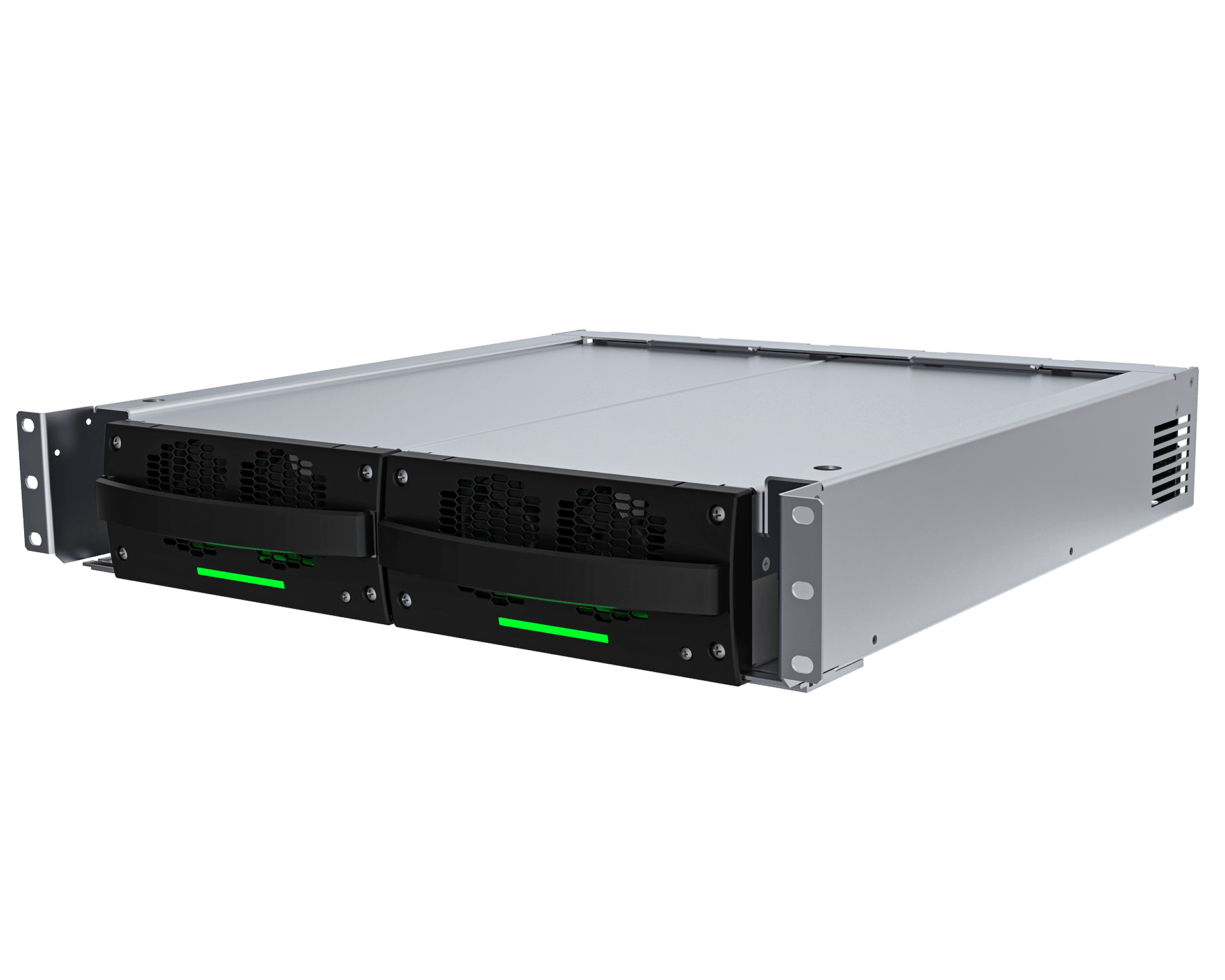
SRX-R 600/30-120
Installation & OperationAER09 Rev 2.0.4, 9 Nov 2026
Download PDF· Rev 2.0.4
CoolMax User Manual
MPPT Solar Charge Controller
Australian Energy Research Laboratories (AERL) was founded in 1985 by Stuart Watkinson to commercialise the Power Optimizer, which he developed while studying at the University of Queensland. It became the AERL MAXIMIZER™, a universal maximum power point tracker (MPPT).
Today AERL designs, integrates and supports power conversion, lithium energy storage, monitoring and earth-fault detection products for commercial, industrial and off-grid energy systems, including oil and gas, mining and telecommunications sites.
Australian Energy Research Laboratories
1/75 Bluestone Circuit
Seventeen Mile Rocks QLD 4073
Australia
Unless specifically agreed to in writing, AERL Pty Ltd:
(a) Makes no warranty as to the accuracy, sufficiency or suitability of any technical or other information provided in its manuals or other documentation.
(b) Assumes no responsibility or liability for loss or damage, whether direct, indirect, consequential, or incidental, which might arise out of the use of such information.
The use of any such information will be entirely at the user’s risk.
AERL and the AERL logo are trademarks owned by AERL Holdings Pty Ltd and used by AERL Pty Ltd under licence. These trademarks may be registered in Australia and other countries.
CoolMax SRX-R Charge Controller User Manual © 2026 AERL Pty Ltd. All rights reserved. Effective November 2026.
This installation manual contains important safety information and installation instructions for the AERL CoolMax SRX-R MPPT Solar Charge Controller. The following symbols indicate ideal installation methods, potentially dangerous conditions, and important operational information.

Information that must be followed to ensure proper installation or operation of the CoolMax SRX-R.

Indicates a critical procedure for the safe installation or operation of the CoolMax SRX-R.
| Warranty | Duration |
|---|---|
| Standard warranty | 2 years |
| Registered within 60 days of installation at aerl.com.au/warranty-registration (or connected to AERL Cloud within 60 days) | 5 years |
| Plus 5, bought from AERL within 60 days of installation | 10 years |
| SRX-R rack shelf | 2 years |
The warranty starts 30 days after AERL dispatches the controller, whether to you, your installer or the business you bought it from. If the controller connects to AERL Cloud before then, the warranty starts on the day it first connects instead.
Our goods come with guarantees that cannot be excluded under the Australian Consumer Law.
Full terms: AERL warranty statement for CoolMax SRX-R, aerl.com.au.
| Weight | 6.2 kg |
| Dimensions (W × H × D) | 192 × 78 × 432 mm |
| Enclosure type | Indoor Type 1 / IP20 |
| Mounting method | 2U Rack |
| Power connectors | Backplane Connector |
| Communications | RS485 / CAN Bus / USB |
| Cooling method | Active (user serviceable) |
| Cabinet air exchange (40 °C intake) | 25 m³/hour |
| Ambient operating temperature* | −20 to 50 °C |
| Storage temperature | −30 to 70 °C |
| Relative humidity | 4–95% non-condensing |
| Max altitude rating | 2000 m |
| Pollution degree (Int & Ext) | II |
| Self-consumption @ idle | 3.5 W |
| Max conversion efficiency | 96% |
| Overvoltage category / protection | DC II / DC Type II |
| Safety protection class | I |
| Nominal battery voltage / range | 120 V / 90–170 |
| Max charge current | 30 A |
| Nominal charge power | 4320 W @ 120 V |
| Max PV input power | Nominal × 2.0 |
| Max PV input voltage (Voc) | 600 V |
| Nominal device voltage | 336 V |
| MPP voltage range (Vmp) | 215–540 V |
| Min PV voltage (MPPT) | 200 V |
| Max PV input current (Imp) | 18 A |
| Max PV short circuit current (Isc) | 25 A |
| Device startup voltage | 60 V (and ≥ Vbat + 10 V) |
| Total backfeed current (Ibf) | 0 A |
| Overload behaviour | Power limitation |
| PV reverse polarity protection | Yes |
| Reverse current protection | Yes |
| Over-temperature protection / derating | Yes |
| Over-voltage / over-current protection | Yes |
| Pre-charge protection | Yes |
| Earth leakage current detection | Yes |
Designed to meet: IEC 62109-1:2010 (safety) · EN 61000-6-3 & EN 61000-6-4 (EMC). *Charge current derates up to 10% per °C above 80% of the upper ambient limit.
Thank you for purchasing an Australian engineered CoolMax SRX-R Series Charge Controller.
CoolMax Charge Controllers deliver an efficient, reliable charging process that maintains battery life while maximising generation from your PV array.
CoolMax Charge Controllers use advanced Maximum Power Point Tracking (MPPT) to extract the maximum power available from your PV array.
AERL’s MPPT algorithm does not lock onto local power peaks, and its tracking losses stay under 0.5% across the array’s full operating temperature range.
This user manual covers CoolMax SRX-R Control Firmware Revisions v2.17.9 and later.
All installations must comply with national and local electrical standards and codes; AERL recommends professional installation. No ongoing maintenance is required.
Installation must comply with the electrical standards, codes, and wiring rules at the site; only an installer accredited or licensed in your jurisdiction should perform the work. Install in a clean, dry location away from direct sunlight. Standards cited elsewhere reflect design intent at publication; refer to current local standards.
Ensure the SOLAR ISOLATOR / BREAKER is in the OFF position before connecting or disconnecting the controller. Do not connect CoolMax controllers in parallel with third-party charge controllers.
CoolMax controllers are designed for floating systems but include provisions for positive functional earthing for telecom applications if required. The chassis ground is marked with the standard earth symbol.
If a negative earth is used for the batteries, load, or DC system, do not functionally earth the array. If damaged, the controller should only be repaired by a qualified service centre; incorrect reassembly risks electric shock or fire.
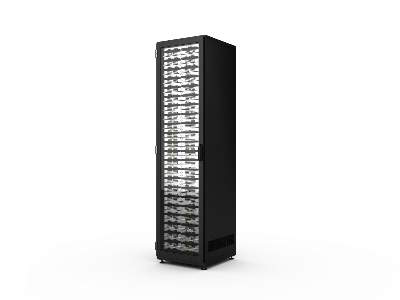
The SRX-R shelf must be mounted horizontally in a suitably ventilated lockable IP5X cabinet, ensuring the backplane area is restricted to licensed electricians and qualified technicians. A representative rack-cabinet installation populated with multiple SRX-R shelves is shown in Figure 1A.
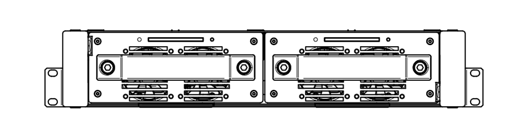
Wire sizes must comply with local and national standards. Input conductors and circuit breakers must be rated at 1.56 × the short-circuit current of the PV array. Copper wiring must be rated at 75 °C or higher.
Use a minimum of #5 AWG (16 mm²) cable for the output between the backplane and the battery bus bar or termination, and use an appropriately sized insulated crimp ferrule when terminating both input and output connections.
Size the protective earth conductor between the SRX-R shelf and the installation’s main earthing system per AS/NZS 5033 Figure 4.13 (earthing-conductor sizing decision tree) or the equivalent installation standard in your jurisdiction. #12 AWG (4 mm²) is the minimum cross-section acceptable at the SRX-R earth stud — it is not a default. Many installations require larger: for example, arrays exposed to lightning-protection requirements (LPS) or installations without DC overcurrent protection typically require 16 mm², or the earth conductor sized to the array cable, whichever is greater. The installer is responsible for the final selection.
Backplane terminations on the shelf use studded connections. Apply the torque values below, using the provided nut and spring washer for each terminal:
| Terminal | Stud | Current rating | Torque |
|---|---|---|---|
| Battery (+ / −) | M10 | 350 A | 17 Nm |
| PV+, PV−, Earth | M5 | 180 A | 2.2 Nm |
For the example scenario of a single SRX-R MPPT module installed in a 2U shelf as the only charge controller on the battery bus, the breaker and configuration below are the recommended setup for that scenario. The breaker below is sized for one module — for other scenarios (a shelf populated with two modules, multi-shelf installations, mixed-controller systems, etc.) contact AERL for guidance on multi-shelf or mixed-controller systems.
Reversing the polarity of either the input or output may damage the CoolMax SRX-R and void product warranty. Confirm polarity with a multimeter prior to closing the input and output circuit breakers.
All SRX-R wiring must enter through the designated backplane entry points. Under no circumstances should holes be drilled into the chassis to make other cable entry points; metal swarf can enter the internal electronics and damage the unit once powered up.
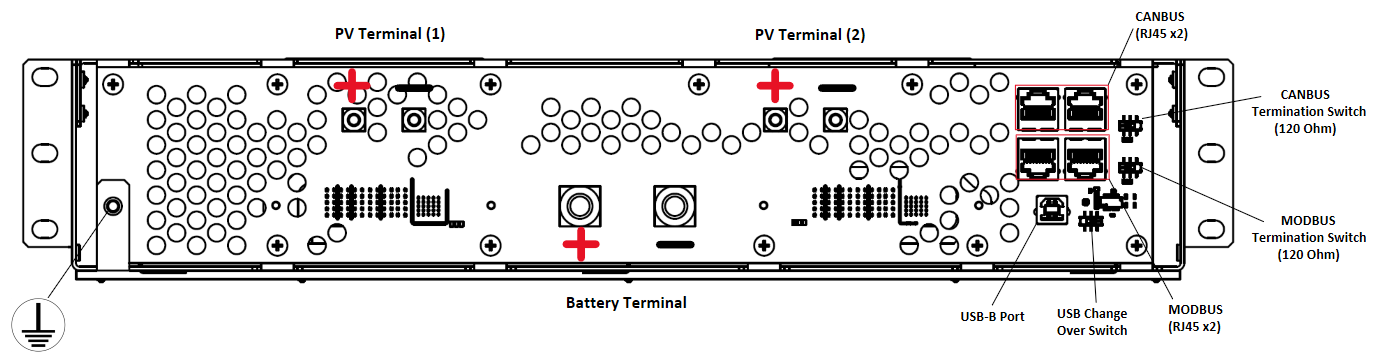
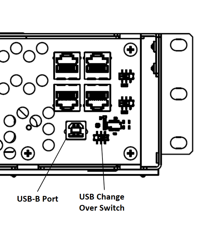
The backplane exposes the following user controls:

The CAN and Modbus buses are shared internally between both module slots, so each switch above is a single shared control that applies to both modules in the shelf. The USB Change-Over switch is the only per-module selector.
The CoolMax SRX-R starts up once the PV input is above 60 Vdc and at least 10 Vdc higher than the connected battery voltage; the device will not power up from the battery terminal. To start: connect the battery first, then turn the PV isolator / breaker on; the LED flashes blue for about 60 seconds, then begins to charge. To shut down: turn the PV isolator off, wait for the LED to turn off, and disconnect the battery breaker.
Do not disconnect the battery fuse / breaker under load. Turn off the PV isolator first per the procedure above.
Do not remove an SRX-R MPPT module from the backplane while charging — turn off the PV isolator first to prevent equipment damage.
When the CoolMax SRX-R is first powered on, the device runs a self-test and the LED indication strip flashes orange to indicate that no charge profile has been configured.
The CoolMax SRX-R is programmed via the USB-B port on the backplane board (Figure 3). Set the USB Change-Over Switch to the module you intend to program (MPPT 1 / MPPT 2) — only one module communicates over USB at a time. The AERL Link software for Windows 10/11 can be downloaded from aerl.com.au/professionals.
The CoolMax SRX-R uses an advanced three-stage charging process with pre-set voltage profiles for each supported nominal battery voltage. The controller does not charge until a charge profile is configured for the connected battery.
The CoolMax SRX-R default charge profile is intended for a generic LiFePO4 battery solution. AERL supports most other chemistries that do not require external BMS communications; always refer to the battery manufacturer’s specifications.
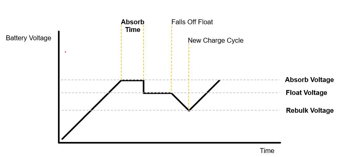
The programmable profile exposes Battery Charge Rate, Tail Current (end-of-absorption threshold), and the Absorb, Float, Re-Bulk, and Equalisation voltage points. Refer to your battery manufacturer’s specifications for the optimal profile; configuration with AERL Link is covered on the next page.
Equalisation is only required for flooded lead-acid cells with sulfation. It is not recommended for LiFePO4 or other lithium-based solutions and will likely cause damage unless advised by the battery manufacturer.
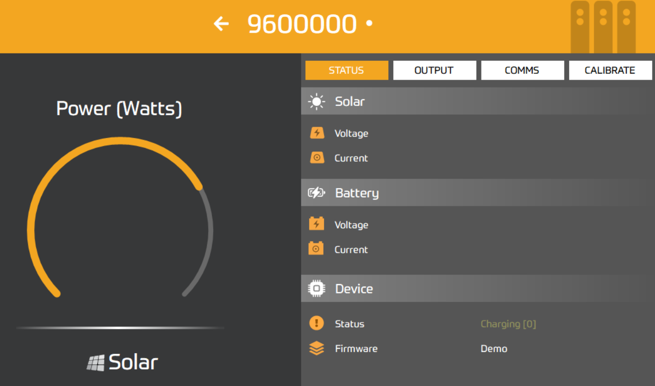
Once the SRX-R is connected over USB, AERL Link opens to the device’s Status tab, the default view for any selected device, providing a live, read-only view of operating values:
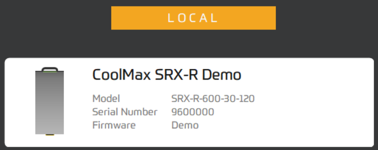
Connect over USB with the USB Change-Over Switch set to the module you wish to program. Within a few seconds the controller registers in AERL Link’s LOCAL devices list. Figure 7 shows the device tile that appears; click its tile to open the device page, then select the OUTPUT tab to adjust the charge profile (Figure 8).
Click the device tile to open its page. On the OUTPUT tab, change values with the +/− arrows or the keyboard, then Apply to commit them to the controller.
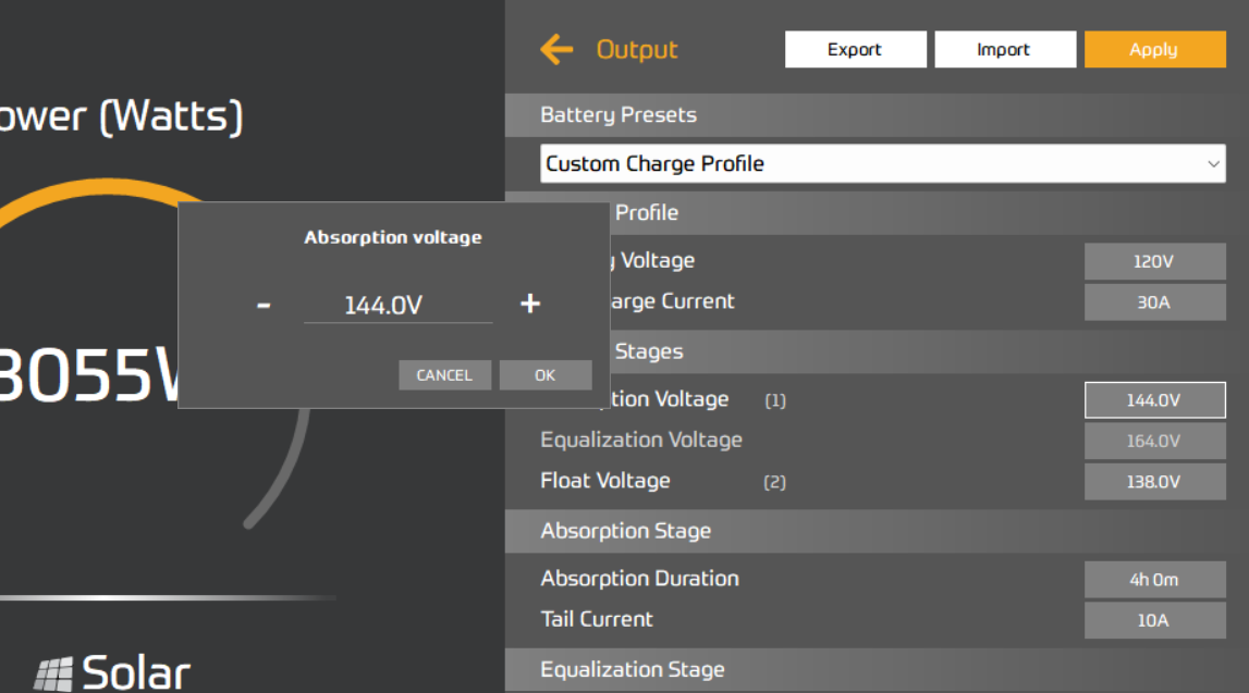
The Battery Preset dropdown on the OUTPUT tab lists pre-tuned profiles for common battery products. Selecting a preset populates the absorption, float, and re-bulk voltages, the absorption time, and the temperature-compensation factor with AERL’s recommended values; presets refresh from AERL HQ on each AERL Link launch with an internet connection. Export saves the current profile to a JSON file and Import applies a saved profile; AERL Link verifies the saved profile’s nominal voltage matches the connected device, and warns before applying a mismatch.
Always cross-check the applied values against your battery manufacturer’s published charge specification before relying on them in a production system.
The CoolMax SRX-R includes a configurable Blackstart Guard that lets the converter begin charging into a battery bank whose voltage is below the controller’s normal “no battery detected” safety threshold (for example, a deeply discharged lithium bank that has been left flat for an extended period and now reads well below its nominal range).
Blackstart Guard is disabled by default. With it disabled, the controller performs its standard start-up safety check: if the output voltage is implausibly low, it refuses to enable and reports a Low Output Voltage / No Battery fault. Enabling Blackstart Guard from the Settings panel in AERL Link bypasses that check, allowing the controller to start charging the depleted bank from a black state.
Leaving Blackstart Guard permanently enabled defeats a key safety check; the controller will no longer refuse to operate into a disconnected or faulty battery.
Temperature compensation measures the temperature of the batteries and adjusts the float and absorb voltage set points by a user-specified factor (mV/°C, per bank). The factory default is 50 mV/°C. Compensation needs a battery temperature reading (see below); without one, the controller charges to the uncompensated set points.
Battery temperature compensation needs a battery temperature reading. The current firmware release does not use a temperature reported by the battery’s BMS over CAN; contact AERL support before relying on temperature compensation.
Many lithium chemistries are damaged by charging below freezing. The SRX-R can be configured to inhibit charging when the remote battery temperature falls below a user-specified threshold. When the Low-Temperature Charge Cutoff is enabled in AERL Link, the controller suspends charging when battery temperature falls below the configured set point and resumes once it rises back above. Both the cutoff temperature and the enable toggle are configured from the Settings panel; the cutoff is disabled by default.
The cutoff only operates when a battery temperature reading is available to the controller; contact AERL support before relying on it. Without a temperature source, the controller cannot enforce the cutoff and charging will proceed regardless of battery temperature.
The CoolMax SRX-R supports field firmware updates over USB via AERL Link. Updates are signed and encrypted; the bootloader will reject a corrupted or unauthorised image.
Before you begin: install the latest AERL Link from aerl.com.au/professionals, ensure the unit is connected to a battery and powered up, and use a stable PC. Do not disconnect USB, kill power, or open the PV / battery isolators during the update.
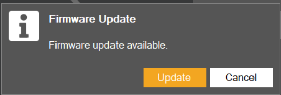
AERL Link refreshes its firmware repository from AERL HQ each time it starts; allow the PC to reach the internet briefly before connecting if it has been offline for a while. If an update fails partway through (e.g. the cable was disconnected or the toggle switch was flipped mid-transfer), retry. The bootloader retains the previous valid image and the controller will continue operating normally until a complete, signed update is received.
Each CoolMax SRX-R is factory calibrated, but field re-calibration can correct for sensor drift or be requested as part of a firmware update. AERL Link guides you through the procedure step by step.
Before you begin: have a multimeter that reads DC to ≥ 0.1 V resolution, a connected battery with output voltage in the normal operating range, a stable DC bus (isolate other charge sources, inverters, and large loads on the same battery), and the MPPT 1 / MPPT 2 toggle switch set to the module being calibrated.
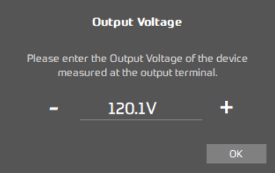
Do not disconnect USB, flip the MPPT toggle switch, or interrupt power during calibration. The output is automatically re-enabled at the end of the procedure; allow it to complete cleanly. AERL Link re-prompts for calibration on first connect after install, and after a calibration-required firmware update; you can also re-run it manually at any time.
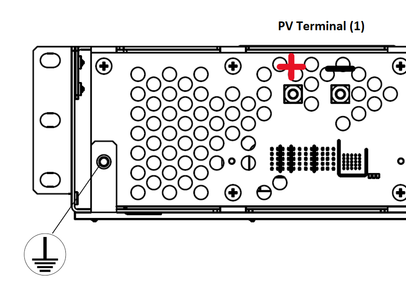
The CoolMax SRX-R features onboard PV and battery system ground-fault detection. All connected poles are checked for insulation degradation during start-up. The device chassis must be connected to the same earth as the PV array for ground-fault detection to function; the chassis earth point is the earth stud on the 2U shelf, at the end of the shelf beside the module terminals, marked with the standard earth symbol (Figure 11).
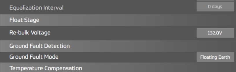
The system earth-type configuration (Ground Fault Mode) must be adjusted in AERL Link for use with functionally earthed systems; otherwise an earth fault will be detected on the earthed pole. The SRX-R supports four mode configurations:
| Mode | Use case |
|---|---|
| Disabled | Ground fault detection is turned off. Not recommended outside of commissioning or test environments. |
| Floating | Default for solar-plus-battery systems with no functional earth on the DC side. Both PV and battery poles are monitored against chassis earth. |
| Positive Earth | The positive PV pole is intentionally bonded to chassis earth, common in some telecommunications applications. Fault detection on the earthed pole is suppressed. |
| Negative Earth | The negative PV pole is intentionally bonded to chassis earth. Fault detection on the earthed pole is suppressed. |
Mis-configuring this setting will either mask a genuine earth fault or trigger a false fault on the intentionally-earthed pole.
The SRX-R trips a ground fault when the insulation resistance of a monitored pole falls below a fixed 50 kΩ. Check that 50 kΩ meets your local standards. Firmware 2.0.1 (February 2024) and later trips at this fixed threshold. Earlier firmware offered a Low/Mid/High setting; update the firmware with AERL Link to get the fixed threshold. The Ground Fault Mode is set in AERL Link (Figure 12).
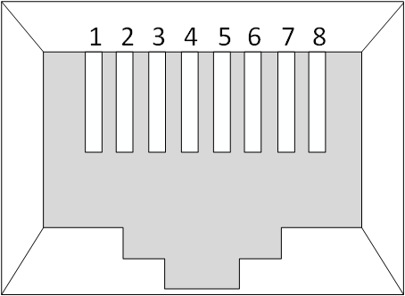
The CoolMax SRX-R supports CAN bus and Modbus RTU (RS485) for remote monitoring; device control (enable/disable, setpoints, firmware updates) is available via CAN only. RS485 and CAN use separate RJ45 sockets on the backplane, two labelled MODBUS and two labelled CANBUS (Figure 2); their pin-outs are below (Figure 13). The register maps are in the CoolMax SRX Modbus RTU and CAN bus protocol documents, available from AERL.
| Pin | MODBUS port (RS485) | CANBUS port |
|---|---|---|
| 3 | RS485-A (non-inv.) | — |
| 4 | — | CAN High |
| 5 | — | CAN Low |
| 6 | RS485-B (inv.) | GND |
| 8 | GND | — |
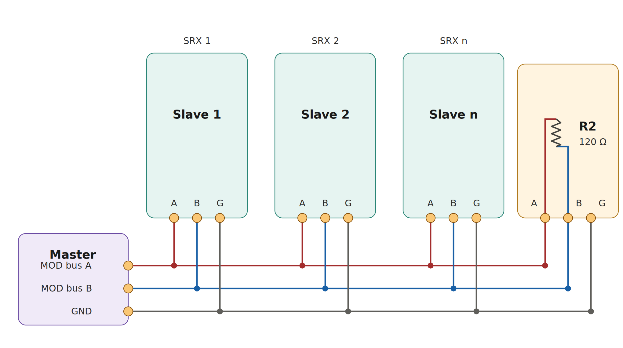
On a Modbus RS485 segment, each SRX-R module sits as a slave on a daisy-chained two-wire bus, with the master at one end. Terminate the bus at both ends with 120 Ω: at the master (many masters have a built-in or switchable terminator) and at the far end, by enabling the 120 Ω termination switch on the last module only.
Bus ID and speed are configured via AERL Link. With the device connected over USB (USB Change-Over switch set to the module being configured), open the Device page, select the COMMS tab, set the fields below (Figure 15), and click Apply Settings. The controller resets briefly when settings are applied. A changed RS485 or CAN bus speed cuts the controller off from any master still using the old speed: update the master to match before you leave the site.
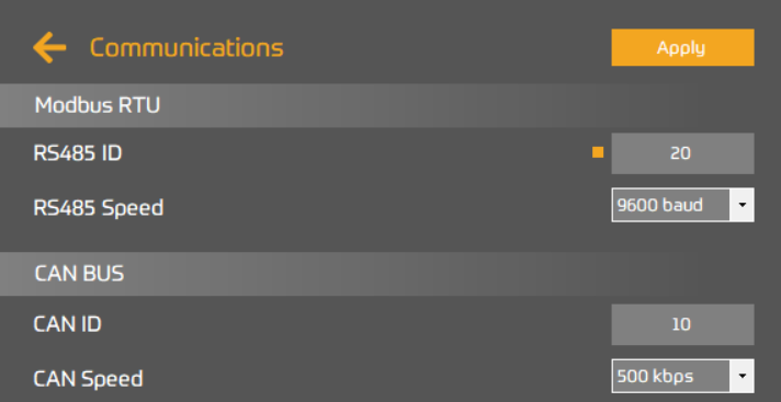
| Field | Range | Default | Notes |
|---|---|---|---|
| Modbus ID | 1–90 | 20 | Unique slave address on the RS485 segment. |
| RS485 speed | 9600 / 19200 / 38400 / 57600 / 115200 baud | 9600 baud | Must match every device on the segment, including the master. |
| CAN ID | 10–60 | 10 | Unique address on the CAN segment. Units on a shared bus take a free ID automatically, skipping 24 and 56 (their frames would alias battery identifiers); 62 means not yet assigned. |
| CAN bus speed | 125 / 250 / 500 kbps | 500 kbps | Must match every device on the CAN segment. |
Each module in a shelf is configured independently; flip the USB Change-Over switch and repeat for the second module.
If the CoolMax SRX-R detects an issue, a warning or fault code is triggered; refer to the tables below.
| Code | LED | Warning | Description | Recommended action |
|---|---|---|---|---|
| −1153 · −1158 | Solid blue | Low input voltage (sleep) | PV voltage below minimum or below battery voltage; device cannot charge. | Confirm PV string configuration is appropriate. May appear at sunrise / sunset. |
| −1162 | Flashing blue | Current flow interrupted | Charge current stopped abruptly, for example a breaker opened or a cable was disconnected. Restarts automatically. | Check PV and battery breakers, fuses and terminations. If recurring, contact AERL. |
| −1400 | Flashing blue | Possible earth fault | An earth-leakage reading at start-up was outside limits; the device re-tests before confirming. Charging continues. | If it recurs or becomes −1401 · −1403, inspect the wiring insulation. |
| −26 | Flashing orange | Device not configured | Initial setup not completed; device will not begin charging. | Connect and configure the device with AERL Link. |
| −1160 | Flashing orange | Configuration out of range | Set-point configuration outside limits for the detected nominal battery voltage. | Confirm the charge profile is appropriate for the battery. Refer to manufacturer recommendations. |
| Code | LED | Warning | Description | Recommended action |
|---|---|---|---|---|
| −1301 | Flashing orange | CAN master lost | Was communicating with the CAN master but has not received a setpoint update within the allowed time-out. | Confirm the RJ45 connection is secure and the master is still active. |
| −1303 | Flashing orange | Waiting for CAN master | CAN-controlled mode, no commands from master yet; charger appears disabled until the master connects. | Check CAN master is powered and sending commands. If standalone is intended, disable CAN control in AERL Link. |
| −1306 | Flashing orange | Charge held: battery voltage limit | Reported by some pre-release firmware: the charge voltage set point is above the maximum charge voltage the battery’s BMS requests over CAN. Charging stops and retries automatically. | Set the absorption and float voltages at or below the battery’s requested charge voltage. |
| −1307 | Flashing orange | Charge held: battery current limit | Reported by some pre-release firmware. | Contact AERL support. |
| 110 | Flashing orange | Firmware update in progress | A firmware update is being installed over CAN; charging is paused. | Wait for the update to finish. Do not remove power or the communications cable. |
| Code | LED | Fault | Description | Recommended action |
|---|---|---|---|---|
| −1 to −99 | Solid red | Generic hardware fault | Any code from −1 to −99 other than −26: a hardware fault found at start-up or during operation. | Power cycle. If persistent, contact AERL for warranty replacement. |
| −150 | Solid red | Measurement fault | The internal measurement circuit stopped providing fresh readings; the converter is stopped. | Power cycle. If persistent, contact AERL. |
| −350 · −1055 · −1161 | Solid red | Temperature sensor fault | Internal or remote temperature sensor missing or unresponsive. | Check communications wiring configuration and ensure connected devices are functioning as expected. If persistent, contact AERL. |
| −365 · −370 · −380 · −390 | Solid red | Startup / precharge fault | Issue during startup or precharge prevented safe converter online. | Power cycle. Check PV / battery isolators, breakers, wiring. If persistent, contact AERL. |
| −367 · −368 · −369 · −371 · −372 · −400 · −401 | Solid red | Critical system fault | Critical system integrity fault; converter locked out for safety. | Power cycle; check comms wiring and power-supply integrity. If persistent, contact AERL. |
| −1050 · −1051 · −1052 · −1053 · −1054 | Solid red | Active cooling fault | An active cooling fan has failed or is operating outside expected parameters. | Check the fan for blockages then power cycle the device. If persistent, contact AERL. |
| −1100 | Solid red | Internal temperature critical | Internal temperature has reached a critical level; device has shut down to prevent damage. | Auto-restart when safe. Ensure adequate clearance and ventilation. |
| −1163 | Solid red | Current sensor fault | A current measurement is outside its physical range; the converter is held off. | Power cycle. If persistent, contact AERL. |
| −360 | 1 flash red | No output detected | Converter enabled but no output current is flowing. | Power cycle. If recurring, contact AERL. |
| Code | LED | Fault | Description | Recommended action |
|---|---|---|---|---|
| −1159 | 2 flashes red | Low output / no battery | No battery detected or output voltage implausibly low. | Confirm battery is connected and output breaker is closed. |
| −1154 | 3 flashes red | High output voltage | Output voltage exceeds the configured maximum. | Battery may be getting charged from a secondary source. Confirm charge parameters across the system. |
| −1155 | 3 flashes red | High battery voltage | Battery voltage exceeds maximum permitted for detected nominal voltage. | Verify battery nominal voltage matches the configured profile. |
| −1305 | 3 flashes red | Battery BMS fault | Fault / alarm received from the battery’s BMS over CAN (e.g. AERL LiFe² battery). | Refer to the battery manufacturer’s manual for BMS troubleshooting. |
| −1157 | 4 flashes red | High output current | Output current exceeds the configured maximum. | Confirm no short on the output; load within device current limit. |
| −1152 | 5 flashes red | High PV voltage | PV input voltage exceeds rated maximum; device shut down to prevent damage. | Confirm string Voc at record-low ambient is within the device’s rating. |
| −1156 | 6 flashes red | High PV current | PV input current exceeds rated maximum. | Confirm string configuration is appropriate for the device. |
| −1102 | 8 flashes red | High battery temperature | Battery temperature sensor over-temperature; high temperatures reduce battery life. | Increase temperature-compensation factor in AERL Link or reduce ambient. |
| −1103 | 9 flashes red | Low battery temperature | Battery temperature sensor under-temperature; low temperatures reduce battery life. | Consider a temperature-controlled battery environment. |
| −1401 · −1402 · −1403 | 10 flashes red | Earth fault detected | Earth fault detected on the input or output. | Isolate the controller, confirm the fault with an insulation resistance tester, and repair it before recommissioning. |
If your situation is not covered here, contact AERL on 1800 950 865 or [email protected].
Australian Energy Research Laboratories
1/75 Bluestone Circuit
Seventeen Mile Rocks QLD 4073
Australia