05Data MappingsDiscrete inputs and Status Flags bit field, Active Event code07
06Data EncodingByte order, signed values, milliunit scaling, worked CRC-1608
07Revision HistoryDocument revision log08
Firmware
Applies to CoolMax SRX and SRX-R firmware 2.0.1 and later. The Min FW column gives the first release with each item.
2.6.9 and 2.8.4 were SRX-R releases only, so an item first released in 2.8.4 reaches the SRX in 2.9.4. 2.6.6 to 2.8.4 have been withdrawn; update units on them to 2.17.9.
CoolMax SRX
Modbus RTU ProtocolRev 2.0.516 Nov 2026
Chapter 01
Bus, Connection and Settings
The CoolMax SRX and SRX-R (firmware 2.0.1 and later) provide read-only access to real-time measurements, fault flags and device information via the standard Modbus RTU protocol over RS485.
Communication Parameters
Parameter
Value
Min FW
Baud rate
9600, fixed
2.0.1
Configurable baud rate
9600 (default) / 19200 / 38400 / 57600 / 115200; set by AERL, as AERL Link cannot change it on 2.17.9 and earlier
2.8.4 (SRX-R) / 2.9.4 (SRX)
Data bits
8
2.0.1
Stop bits
1
2.0.1
Parity
None
2.0.1
Device address
20 (default); configurable 1–90 with AERL Link; a setting outside 1–90 is used as 20
2.0.1
CRC
Modbus CRC-16 (transmitted LSB first)
2.0.1
The broadcast address 0 is not supported; every request is addressed to one unit. Only the function codes in Chapter 02 are supported.
Frame Timing
Modbus RTU frames are delimited by idle time on the bus: a frame is treated as complete once the bus has been silent for the inter-frame gap period.
Firmware before 2.19.6 uses an inter-frame gap of about 8 ms at every baud rate. From 2.19.6 the gap follows the rate: 8 ms at 9600 baud, 4 ms at 19200 and 3 ms at 38400 baud and above. Allow for that gap, a short processing delay, and the transmission time of the response, which at 9600 baud is 126 ms for a full 58-register read.
Set the response timeout to at least 250 ms at 9600 baud, and wait for the response, or for the timeout to expire, before sending the next request. Requests must not be overlapped: a second request that arrives before the first has been answered is discarded along with it.
CoolMax SRX
Modbus RTU ProtocolRev 2.0.516 Nov 2026
Chapter 01 · continued
Physical Connection
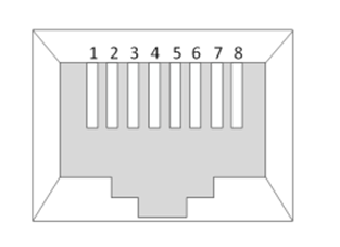
RS485 uses the two paralleled RJ45 sockets labelled MODBUS, separate from the two CAN sockets. The pin-out differs: pin 6 is RS485-B here and GND on a CAN socket, so do not plug a CAN cable into a MODBUS socket.
RJ45 connector viewed from the front: contacts numbered 1 to 8, left to right.
Pin
Signal
3
RS485-A (non-inverting)
6
RS485-B (inverting)
8
GND
All other pins are unused.
Network Topology
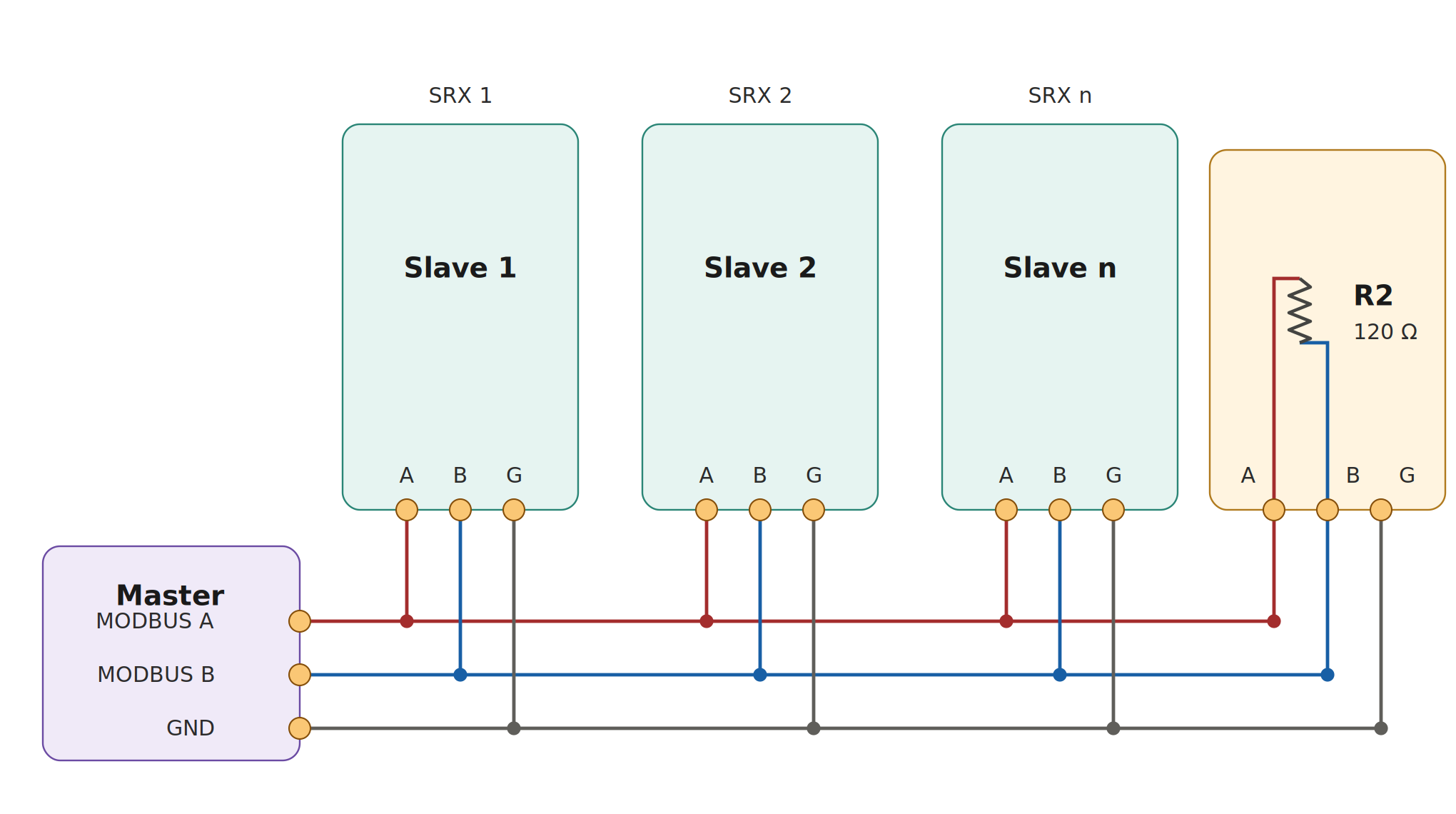
The Modbus network is a linear bus, with short stubs branching from ‘T’ connectors on the main backbone to each device. Terminate the bus at both ends with a 120 Ω resistor between the RS485-A and RS485-B signals: at the master (many masters have a built-in or switchable terminator) and at the far end of the backbone.
Linear two-wire RS485 bus plus GND: master daisy-chained to SRX units (A / B / G), with 120 Ω termination across A and B at the far end of the backbone.
Each CoolMax SRX is pre-fitted with a switchable 120 Ω termination, enabled by the slide switch next to the MODBUS sockets. Enable it on the SRX at the far end of the backbone only, and leave it off on every other SRX.
CoolMax SRX
Modbus RTU ProtocolRev 2.0.516 Nov 2026
Chapter 02
Supported Function Codes
0x02Read Discrete InputsMin FW 2.0.1
Read one or more fault flags as single bits. On firmware before 2.19.5 the quantity is 1–26 and start address + quantity must not exceed 26: inputs 10027–10032 cannot be read with 0x02, so read bit 26 from the Status Flags register (30027). From 2.19.5 the limit is 32. Inputs are packed eight per byte, first requested input in the LSB; a final partial byte is padded with zeros.
Read 2 registers starting at offset 8 (PV Voltage, 30009–30010)
Response
14 04 04 00 06 2E 83 03 45
Byte count = 4, value = 0x00062E83 = 405 123 mV = 405.123 V
0x0BGet Comm Event CounterMin FW 2.19.5
Read the count of successful 0x02 / 0x04 responses since power-up. Firmware before 2.19.5 answers 0x0B, but its response leaves out the function-code byte; the standard response below needs 2.19.5.
Status is always 0. The counter is 16-bit and wraps.
All other function codes return an Illegal Function (01) exception. In particular 0x03 Read Holding Registers, the default in many Modbus tools, is not supported: configure the client for input registers (0x04).
Example: 14 83 01 91 34 answers an unsupported 0x03 request. A request whose CRC fails is discarded without a response.
Chapter 04
Modbus Register Map
Addressing
Register reference numbers (1xxxx for discrete inputs, 3xxxx for input registers) are a documentation convention only. The value placed on the wire is the zero-based offset: input 10001 is addressed as 0x0000 under function 0x02, and register 30001 is addressed as 0x0000 under function 0x04.
CoolMax SRX
Modbus RTU ProtocolRev 2.0.516 Nov 2026
Chapter 04 · continued
Input Registers (FC 0x04)
All registers are read-only 16-bit words. Multi-register values are big-endian: the register at the lowest address holds the most significant word.
Address
Offset
Regs
Description
Type
Unit / notes
Min FW
30001–30004
0–3
4
Product ID
UInt64
Device type code, zero-extended
2.0.1
30005–30008
4–7
4
Serial Number
UInt64
Allocated at manufacture
2.0.1
30009–30010
8–9
2
PV Voltage
Int32
mV
2.0.1
30011–30012
10–11
2
PV Current
Int32
mA
2.0.1
30013–30014
12–13
2
Output Voltage
Int32
mV
2.0.1
30015–30016
14–15
2
Output Current
Int32
mA
2.0.1
30017–30020
16–19
4
Reserved
UInt64
Always 0
2.0.1
30021–30022
20–21
2
Power (see below)
Int32
mW; output power before 2.19.6, see below
2.0.1
30023–30024
22–23
2
Case Temperature
Int32
m°C (25 000 = 25.0 °C), see below
2.0.1
30025–30026
24–25
2
Active Event
Int32
Signed event code, see page 8
2.0.1
30027–30030
26–29
4
Status Flags
UInt64
Bit field, bits 0–31 used, see page 7
2.0.1
30031–30034
30–33
4
Reserved
UInt64
Ignore: reads 0x1234567890ABCDEF before 2.19.5, 0 from 2.19.5
2.0.1
30035–30038
34–37
4
Reserved
UInt64
Always 0
2.0.1
30039–30040
38–39
2
Battery Temperature
Int32
m°C; 0 until a value is received, see below
2.0.1
30041–30044
40–43
4
Hardware Version
8 × ASCII
Reads AER09SRX
2.0.1
30045–30048
44–47
4
Firmware Version
8 × ASCII
First 8 characters of the version string: V2.17.9.0 reads V2.17.9.
2.0.1
30049–30050
48–49
2
Model Type
UInt32
Device type code
2.0.1
30051–30054
50–53
4
Product ID (mirror)
UInt64
Mirror of 30001–30004
2.0.1
30055–30058
54–57
4
Serial Number (mirror)
UInt64
Mirror of 30005–30008
2.0.1
The four telemetry values (PV and output voltage and current) are positive in normal operation; a small negative reading can appear at zero current or voltage from sensor offset.
Power (30021) before 2.19.6 holds the MPPT tracker’s last power sample, which with the default sensor configuration is output power (output voltage × output current). The value is held, stale, while the converter is stopped: read it together with the Status Flags. From 2.8.4 (SRX-R) / 2.9.4 (SRX) it is 0 or above. From 2.19.6 it is PV power, PV voltage × PV current, calculated live.
Case Temperature comes from the power-stage sensor.
Battery Temperature comes from a CAN Remote Temperature message or an external sensor. It reads 0 until the first value arrives, then holds the last value received. Values outside −10 to 100 °C are ignored.
CoolMax SRX
Modbus RTU ProtocolRev 2.0.516 Nov 2026
Chapter 05
Data Mappings
Discrete Inputs and Status Flags
The 32 discrete inputs (FC 0x02, 10001–10032) and bits 0–31 of the Status Flags (30027–30030) are the same fault flags; bits 32–63 are always 0, and the numbering matches the CAN Active Flags broadcast. A flag reads 1 when its condition is active. On 2.17.9 and earlier the Status Flags are a latched snapshot, updated when a fault is raised or cleared, not a live view of each condition. Min FW is the first firmware with the flag.
Bit
Input
Flag
Description
Min FW
0
10001
Hardware Fault (Generic)
Generic hardware fault; also a battery BMS alarm
2.0.1
1
10002
No Config Data
No configuration data set
2.0.1
2
10003
Config Data Out of Range
Configuration out of range; from 2.19.5, also a charge target outside the BMS limits
2.0.1
3
10004
Battery Sense Lost
Battery Sense no longer responding
2.0.1
4
10005
CAN Master Lost
CAN master lost
2.0.1
5
10006
Internal Over Temp
Internal temperature fault
2.0.1
6
10007
Vin Low Fault
Input voltage too low
2.0.1
7
10008
Vout Low Fault
Output voltage too low
2.0.1
8
10009
Vout High Fault
Output voltage too high
2.0.1
9
10010
Vin High Fault
Input voltage too high
2.0.1
10
10011
High PV Current
PV input current too high
2.0.1
11
10012
Over Temp Fault
Device temperature exceeds maximum
2.0.1
12
10013
Low Battery Temp
Low battery temperature (separate from cut-off)
2.0.1
13
10014
Earth Fault Positive
Earth fault on the positive conductor
2.0.1
14
10015
Earth Fault Negative
Earth fault on the negative conductor
2.0.1
15
10016
Active Cooling Fault
Fan fault
2.0.1
16
10017
Output Over-Current
Output current too high; on bit 24 from 2.19.5
2.0.1
17
10018
Iin High Fault
Input current too high
2.0.1
18
10019
Cross Check Fault
Cross-check failed
2.0.1
19
10020
Temp Sensor Timeout
Temperature sensor unresponsive
2.0.1
20
10021
Earth Fault
Low isolation resistance; clears after about 30 min from 2.6.6, held until reset from 2.19.6
2.0.1
21
10022
No Output Fault
No output detected
2.0.1
22
10023
Low Bat Temp Cut-off
Low battery temperature cut-off active
2.0.1
23
10024
High Bat Temp Cut-off
High battery temperature cut-off active
2.0.1
24
10025
Current Flow Disrupted
Charging interrupted (incl. output over-current)
2.0.1
25
10026
Pre-charge Failure
Pre-charge failure
2.0.1
26
10027
PV Pre-charge Failure
PV input pre-charge failure
2.8.4 (SRX-R) / 2.9.4 (SRX)
27
10028
PWM Regulation Failure
Current flowing while PWM disabled
2.19.5
28
10029
PWM Corruption
PWM state corruption detected
2.19.5
29
10030
Stack Overflow
Internal stack overflow detected
2.19.5
30
10031
Clock Failure
Clock failure (CSS / drift) detected
2.19.5
31
10032
Brownout
Brown-out detected
2.19.5
CoolMax SRX
Modbus RTU ProtocolRev 2.0.516 Nov 2026
Chapter 05 · continued
Active Event (Registers 30025–30026)
A single signed Int32 event code, not a bit field. 0 = no event (cleared once all flags clear and the converter re-enables). Negative values are fault codes, for example −1100 = temperature exceeds maximum; positive values are informational events, for example 101 = fault recovered. The register holds the most recent code raised. A battery BMS alarm shows here as −1305. Decode as two’s complement. The SRX user manual’s troubleshooting chapter lists the codes an installer sees; the full list is available from AERL on request.
Chapter 06
Data Encoding
16-bit registers: big-endian (MSB first). Value 0x2E83 is transmitted as [0x2E, 0x83].
32-bit and 64-bit values: split across 2 or 4 consecutive registers, most significant register at the lowest address. PV Voltage 405.123 V = 405 123 mV = 0x00062E83 is read from 30009 = 0x0006 and 30010 = 0x2E83.
Signed values: two’s complement over the full 32-bit width. −1100 = 0xFFFFFBB4.
Milliunit scaling: mV, mA, mW and m°C; divide by 1000 for V, A, W and °C.
Character fields: 8 ASCII bytes packed two per register in string order, no terminator.
All values are transmitted as integers; no floating-point encoding is used.
CRC-16
Every frame ends with a 16-bit CRC computed over all preceding bytes using polynomial 0xA001 (0x8005 reflected) with an initial value of 0xFFFF, and transmitted low byte first.
Frame (without CRC)
CRC-16
On the wire (CRC appended, low byte first)
14 04 00 08 00 02
0xCCF2
14 04 00 08 00 02 F2 CC
14 04 04 00 06 2E 83
0x4503
14 04 04 00 06 2E 83 03 45 (response)
Chapter 07
Revision History
Rev.
Date
Change
–
–
Earlier revisions: see previous editions.
2.0.2
10/09/26
Reorganised for integrators.
2.0.3
08/11/26
Updated for firmware 2.19.6: register 30021 is PV power; inter-frame gap per baud rate; flag notes; MODBUS sockets have their own pin-out; bus termination clarified.
2.0.4
09/11/26
Minimum firmware marked on items that need firmware later than 2.17.9.
2.0.5
16/11/26
Minimum firmware for every register, function and flag, from 2.0.1; corrections for firmware 2.17.9 and earlier.

 CoolMax SRX