Modbus RTU frames are delimited by idle time on the bus: a frame is treated as complete once the bus has been silent for the inter-frame gap period.
The CoolPro uses a fixed inter-frame gap of approximately 8 ms, independent of the configured baud rate. This is comfortably wider than the 3.5-character silent interval required by the Modbus specification at every supported baud rate, so a standard-compliant master will interoperate without adjustment.
Physical Connection
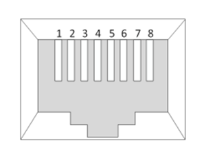
The CoolPro uses an 8-pin RJ45 connector for its RS485 interface.
RJ45 connector viewed from the front — contacts numbered 1 to 8, left to right.
Pin
Signal
3
RS485-A (non-inverting)
6
RS485-B (inverting)
8
GND
All other pins are unused.
CoolPro
Modbus RTU ProtocolRev 1.0.18 Nov 2026
Chapter 01 · continued
Network Topology
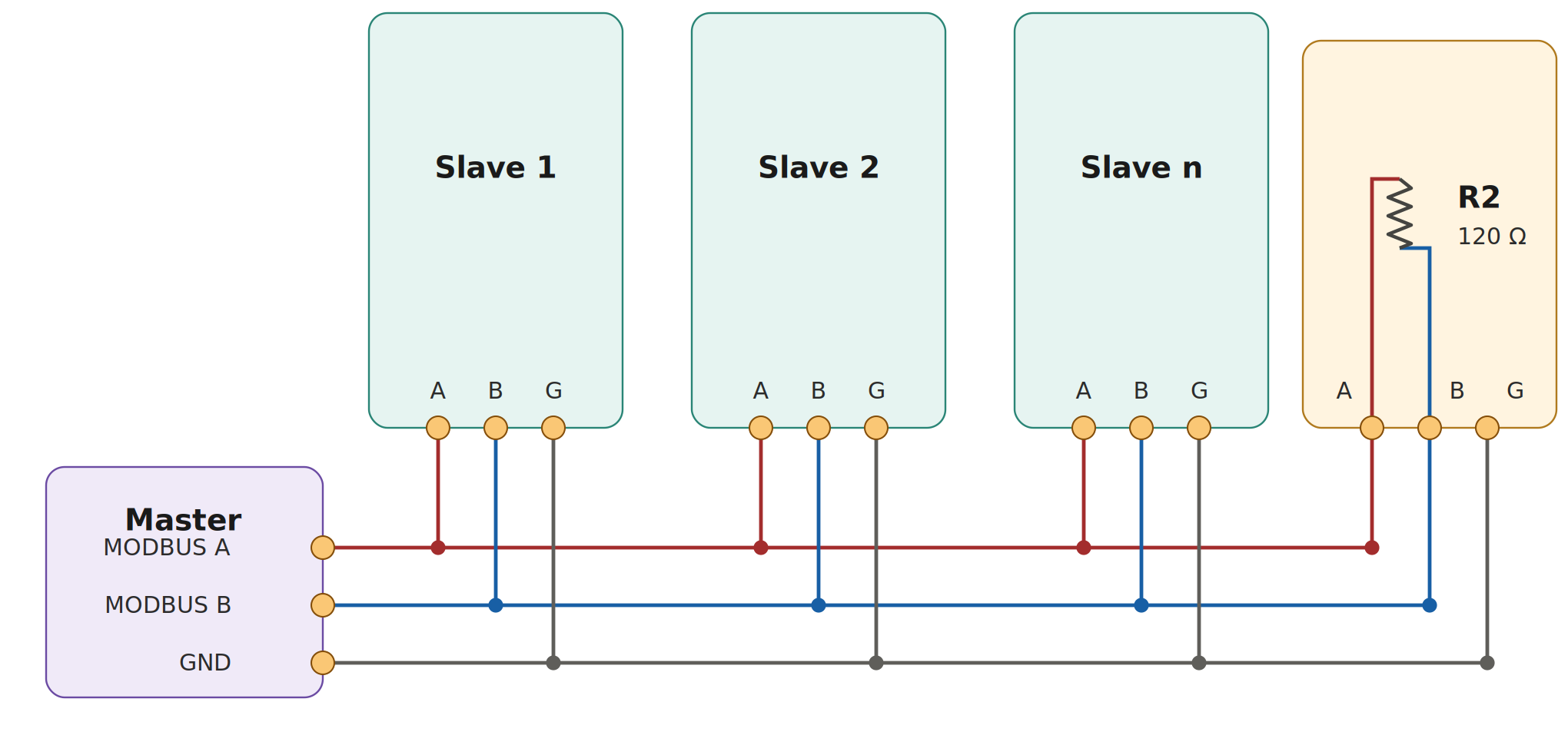
The Modbus network is a linear bus, with short stubs branching from ‘T’ connectors on the main backbone to each device. Terminate the bus at both ends with a 120 Ω resistor between the RS485-A and RS485-B signals: at the master (many masters have a built-in or switchable terminator) and at the far end of the backbone.
Linear two-wire RS485 bus — master daisy-chained to slave devices (A / B / G), with 120 Ω termination across A and B at the far end of the backbone (the master end is terminated at the master).
Register reference numbers (4xxxx for holding registers, 3xxxx for input registers) are a documentation convention only. The value placed on the wire is the zero-based PDU address, shown in the Offset column — that is, on-wire address = reference number − 40001 (holding) or − 30001 (input) = the offset.
Holding register 40001 is addressed on the wire as 0x0000 (function 0x03 / 0x06).
Input register 30001 is addressed on the wire as 0x0000 (function 0x04).
The function code — not the reference range — selects the address space, so the same on-wire address 0x0000 reads the device address under 0x03 and the input voltage under 0x04.
CoolPro
Modbus RTU ProtocolRev 1.0.18 Nov 2026
Chapter 03 · continued
Holding Registers (FC 0x03, 0x06)
Configuration registers (read / write). All values are uint16.
Register 40003 is a write-only command trigger. A read always returns 0 regardless of the value last written — this is expected behaviour, not a fault. The written value initiates the reset and is never stored.
Input Registers (FC 0x04) — Live Telemetry (Offsets 0–7)
All values are uint16 with milliunit scaling.
Address
Offset
Description
Unit
Conversion
30001
0
Input Voltage
mV
voltage_v = value / 1000
30002
1
Input Current
mA
current_a = value / 1000
30003
2
Output Voltage
mV
voltage_v = value / 1000
30004
3
Output Current
mA
current_a = value / 1000
30005
4
Temperature
m°C
temp_c = value / 1000
30006
5
Uptime (Low Word)
s
Low 16 bits of uptime
30007
6
Uptime (High Word)
s
High 16 bits of uptime
30008
7
Status Flags
—
Bit field (see below)
Status Flags Bit Field (Register 30008)
A 16-bit bit field. Each bit reports a specific system condition and can be set or cleared independently.
Bit
Hex
Name
Description
0
0x0001
System Startup
Device is initialising (cleared once startup completes)
1
0x0002
Daily Reset
Daily reset has occurred (uptime counter reset)
2
0x0004
Input Measurement Fault
Fault communicating with the input measurement sensor
3
0x0008
Output Measurement Fault
Fault communicating with the output measurement sensor
4
0x0010
Calibration Invalid
Stored calibration data failed validation
5
0x0020
Calibration Missing
No calibration data stored
6
0x0040
Temperature Sensor Fault
Fault communicating with the temperature sensor
7–15
—
Reserved
Reserved for future use (currently 0)
CoolPro
Modbus RTU ProtocolRev 1.0.18 Nov 2026
Chapter 03 · continued
Device Information Registers (Offsets 100–107)
Address
Offset
Description
Type
Notes
30101
100
Serial Number Low
uint16
Low 16 bits
30102
101
Serial Number High
uint16
High 16 bits
30103
102
Hardware Revision
uint16
e.g. 1, 2, 3
30104
103
Firmware Major Version
uint16
e.g. 1
30105
104
Firmware Minor Version
uint16
e.g. 0
30106
105
Firmware Patch Version
uint16
e.g. 0
30107
106
Manufacture Date Low
uint16
Unix timestamp low word
30108
107
Manufacture Date High
uint16
Unix timestamp high word
Chapter 04
Data Encoding
16-bit registers
Byte order: big-endian (MSB first).
Example: value 24500 (0x5FB4) is transmitted as [0x5F, 0xB4].
Milliunit scaling
All measurements use milliunits so values carry as integers without floating point:
Voltage: millivolts (mV) — divide by 1000 for volts.
Current: milliamps (mA) — divide by 1000 for amps.
Temperature: millidegrees Celsius (m°C) — divide by 1000 for °C.
For example, an input-voltage reading of 24500 is 24.5 V, and a temperature reading of 25800 is 25.8 °C.
32-bit values
Uptime, serial number and manufacture date span two uint16 registers:
Split: low word first, high word second.
Byte order: big-endian within each register.
Example — value 70000 (0x00011170) is stored as:
Register
Hex
Value
N (low)
0x1170
4464
N+1 (high)
0x0001
1
Reconstruct: (high << 16) | low = 70000. All values are transmitted as integers; no floating-point encoding is used.
Conversion Examples
Quantity
Register value
Meaning
24.5 V
24500
24500 mV
3.25 A
3250
3250 mA
25.8 °C
25800
25800 m°C
Uptime 70000 s
offset 5 = 4464, offset 6 = 1
Combined: 0x0001_1170
CoolPro
Modbus RTU ProtocolRev 1.0.18 Nov 2026
Chapter 04 · continued
CRC-16
Every frame ends with a 16-bit CRC computed over all preceding bytes using polynomial 0xA001 with an initial value of 0xFFFF, and transmitted low byte first.

 CoolPro