 Download PDF· Rev 2.0.3
User Manual
EarthGuard
Insulation Monitoring Device
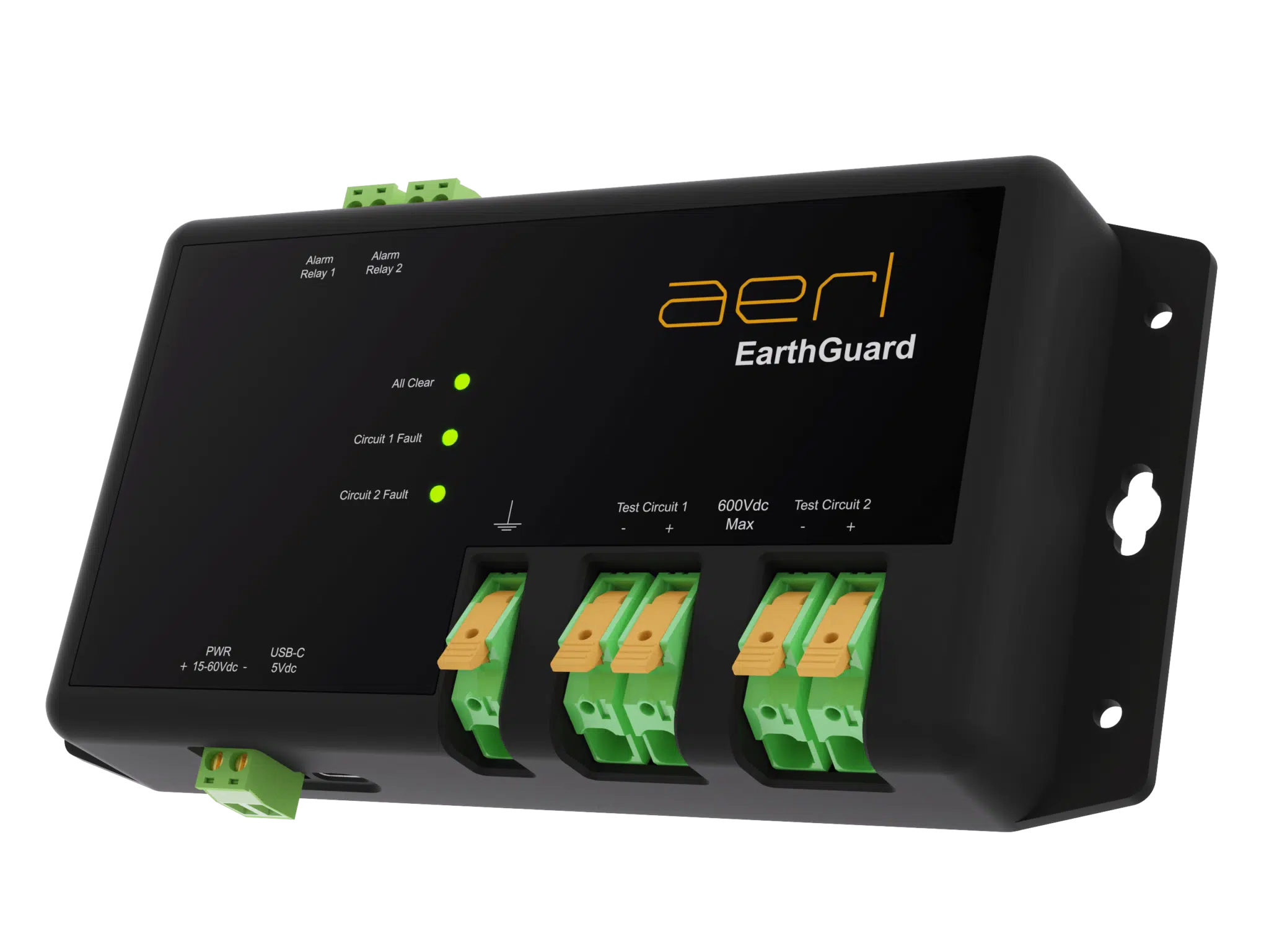
EG-600
Installation & OperationAER12 Rev 2.0.3, 9 Nov 2026
Download PDF· Rev 2.0.3
User Manual
Insulation Monitoring Device
Australian Energy Research Laboratories (AERL) was founded in 1985 by Stuart Watkinson to commercialise the Power Optimizer, which he developed while studying at the University of Queensland. It became the AERL MAXIMIZER™, a universal maximum power point tracker (MPPT).
Today AERL designs, integrates and supports power conversion, lithium energy storage, monitoring and earth-fault detection products for commercial, industrial and off-grid energy systems, including oil and gas, mining and telecommunications sites.
Australian Energy Research Laboratories
1/75 Bluestone Circuit
Seventeen Mile Rocks QLD 4073
Australia
Unless specifically agreed to in writing, AERL Pty Ltd:
(a) Makes no warranty as to the accuracy, sufficiency or suitability of any technical or other information provided in its manuals or other documentation.
(b) Assumes no responsibility or liability for loss or damage, whether direct, indirect, consequential, or incidental, which might arise out of the use of such information.
The use of any such information will be entirely at the user’s risk.
AERL and the AERL logo are trademarks owned by AERL Holdings Pty Ltd and used by AERL Pty Ltd under licence. These trademarks may be registered in Australia and other countries.
EarthGuard EG-600 User Manual © 2026 AERL Pty Ltd. All rights reserved.
This manual contains important safety information and installation instructions for the EarthGuard EG-600 insulation monitoring device. It uses the following symbols for important operating information and potentially dangerous conditions.

Information you must follow for the EarthGuard to operate correctly.

A procedure that is critical to installing the EarthGuard safely. Take extreme care when you perform it.
The installation must comply with the electrical standards, codes and wiring rules in force at the site, and must be done by an installer accredited or licensed for solar PV and battery systems in your jurisdiction. Standards cited in this manual reflect the design intent at publication; where your current local standards differ, follow them.
This manual covers EarthGuard EG-600 firmware v2.0.0 and later.
| Warranty requirements | Total duration |
|---|---|
| You are the original purchaser of the EarthGuard. | 2 years |
The warranty starts 30 days after AERL dispatches the EarthGuard.
Our goods come with guarantees that cannot be excluded under the Australian Consumer Law. You are entitled to a replacement or refund for a major failure and compensation for any other reasonably foreseeable loss or damage. You are also entitled to have the goods repaired or replaced if the goods fail to be of acceptable quality and the failure does not amount to a major failure.
Full terms: AERL warranty statement for the EarthGuard EG-600 and EG-600-SC, aerl.com.au.
Register your EarthGuard at aerl.com.au/warranty-registration. Registration does not change the 2-year warranty.
| Parameter | Typical |
|---|---|
| Weight | 300 g |
| Dimensions (W × H × D) | 170 × 90 × 35 mm |
| Enclosure type | Indoor Type 1 / IP20 |
| Operating temperature | −25 to 60 °C |
| Storage temperature | −25 to 80 °C |
| Connection terminals (Test & Earth) | Lever push-in · 0.2–10 mm² (22–8 AWG) |
| Parameter | Value |
|---|---|
| Input power (DC input) | 12–60 Vdc |
| Max current draw (DC input) | 100 mA |
| Input power (USB-C) | 4.5–5.5 Vdc |
| Max current draw (USB‑C) | 250 mA |
| Alarm indication relays | 2 × signal (dry contact), NO, fail‑safe |
| Parameter | Value |
|---|---|
| Voltage range | 40–600 Vdc |
| Leakage trip threshold (±10%) | 30 kΩ, fixed (firmware 2.2.1) |
| Isolation to LV side | 4 kV (transient) |
| Domain | Standard |
|---|---|
| Electrical Safety | AS/NZS 3100:2017 |
| EMC | AS/NZS 61000.6.3:2012 |
Intended for installations designed to the applicable local standards in the jurisdiction of use. In Australia/NZ: AS/NZS 3000, AS/NZS 5033, AS/NZS 5139.
The EG-600 is a standalone dual-channel insulation monitoring device, designed to support compliance with AS/NZS 5033 (PV arrays), AS/NZS 5139 (battery systems) and other applicable local standards. It monitors conductor insulation from 40–600 Vdc and provides integrated audio/visual alarms plus per-circuit fail-safe relay outputs for external fault notification.
Resistive earth-fault detection: a small test current is injected between each system conductor and earth, and the resulting insulation resistance is measured. When resistance falls below the configured trip threshold an alarm is raised. Installed on the battery bus, a single unit typically covers both the battery bank and PV array in common-positive / common-negative regulator topologies.
All AERL products are verified compatible. Some third-party devices may exceed permissible leakage thresholds and trigger immediate fault detection on power-up.
Check the device’s earth-leakage specification before installation. If the EarthGuard reports a fault at power-up with no insulation fault present, contact AERL.
Whether earth-fault detection is required, on which side(s), and at what threshold depends on installation voltage, power rating and PCE topology. The applicable standards (in Australia/NZ, AS/NZS 5033 and AS/NZS 5139) may change between editions — the installer determines what applies.
Common-positive / common-negative regulators: a single EarthGuard on the battery side typically covers both battery and PV-array circuits. Confirm against your applicable standard.
Requirements depend on the decisive voltage class of the battery side — refer to your applicable installation standard and PCE manufacturer documentation.
Fix the EarthGuard to a vertical surface through the mounting holes in the chassis flanges.
Use hardware that suits the surface: expansion anchors for concrete, toggle bolts for plasterboard, machine screws for metal. Check that the unit is level and every mounting point is secure.
Install the EarthGuard in a clean, dry location, out of direct sunlight and away from moisture.
The EarthGuard monitors DC buses from 40 to 600 Vdc: 48 V and 120 V battery systems and solar PV arrays.
Wear suitable personal protective equipment (PPE) near live connections, and disconnect all power sources before you change any wiring.
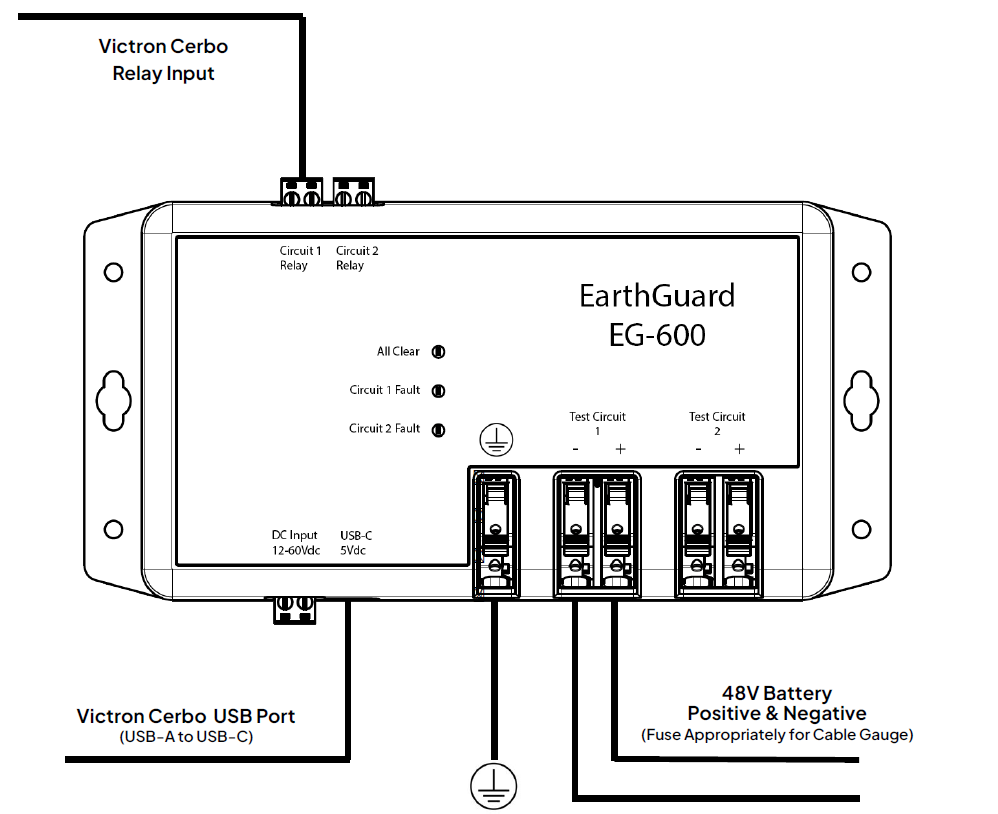
Supply the EG-600’s 12–60 Vdc input from a current-limited AC–DC or DC–DC power supply. Do not connect it directly to a battery or any other source that is not current-limited: a fault could draw enough current to cause damage or a fire.
Connect a PC to the USB-C port and use AERL Link to view measurements, set the sensitivity and update the firmware. AERL Link shows each circuit’s voltage and earth resistance (+ and −) in MΩ, with the device status and firmware version.
AERL Link runs on Windows 10 and 11. Download it from aerl.com.au/professionals.
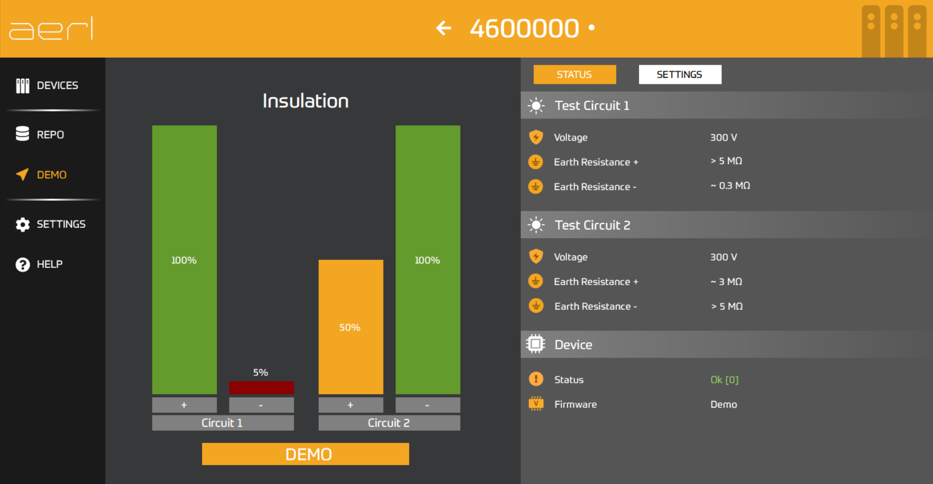
Choose one of three trip sensitivity levels in AERL Link. The default is Low (30 kΩ).
On firmware 2.2.1, the current release, the trip threshold is fixed at 30 kΩ (Low) whatever sensitivity is set.
Set each circuit’s mode in AERL Link to match how its DC bus is referenced to earth.
Positive Earth and Negative Earth modes disable monitoring on the bonded pole for that circuit. Use these modes only when the indicated pole is deliberately and permanently bonded to earth at another point in the installation; otherwise leave the circuit on Floating.
Two dry-contact signal relays, one per circuit, on the top-edge pluggable terminals connect to an external monitor (for example a Victron Venus GX) where the local alarm cannot be heard.
Each contact is Normally Open (NO) and energise-to-close (fail-safe): it is closed in normal operation and opens on an earth fault on its circuit or on loss of power. An earth fault, a power loss and a broken cable all show the external monitor the same open contact.
The EG-600 continuously monitors the insulation between each pole of each test circuit and reference earth. When it detects a fault it lights that circuit’s Fault LED, sounds the buzzer and opens that circuit’s relay.
The LEDs and buzzer show the device state:
| Condition | All Clear | Circuit 1 fault | Circuit 2 fault | Buzzer |
|---|---|---|---|---|
| All Clear (insulation OK) | On | Off | Off | Off |
| Circuit 1 earth fault (DC+ or DC−) | Off | On | Off | Pulsing |
| Circuit 2 earth fault (DC+ or DC−) | Off | Off | On | Pulsing |
Note — All Clear is green; the Circuit Fault LEDs are red. In a fault the buzzer sounds for about 1.5 s, then is silent for 1.5 s, until the fault clears. When the insulation recovers, the EG-600 returns to All Clear and closes the relay. AERL Link shows the device status, including an internal self-test fault.
An earth fault can damage power conversion equipment (PCE) and connected components. Ask the PCE manufacturer before you simulate an earth fault. AERL takes no responsibility for damage caused by simulating an earth fault.
To check that the EG-600 is working, follow this procedure with extreme caution.

If the test does not trip the EarthGuard, or your installation is not covered here, contact AERL support at [email protected] or on 1800 950 865.
Record how this EarthGuard is set up and keep this manual with the installation.
| Site | |
|---|---|
| Installed by | |
| Licence number | |
| Installation date | |
| Serial number | |
| Firmware version | |
| Supply | 12–60 Vdc inputUSB-C |
| Monitors | |
|---|---|
| Ground fault mode | FloatingPositive EarthNegative Earth |
| Trip sensitivity | HighMidLow |
| Relay 1 connected to |
| Monitors | |
|---|---|
| Ground fault mode | FloatingPositive EarthNegative Earth |
| Trip sensitivity | HighMidLow |
| Relay 2 connected to |
| Date and result |
|---|
Australian Energy Research Laboratories
1/75 Bluestone Circuit
Seventeen Mile Rocks QLD 4073
Australia