 Download PDF· Rev 1.0.0
Installation and Operation User Manual
Industrial HMI
10.1″ Sunlight-Readable Touch HMI
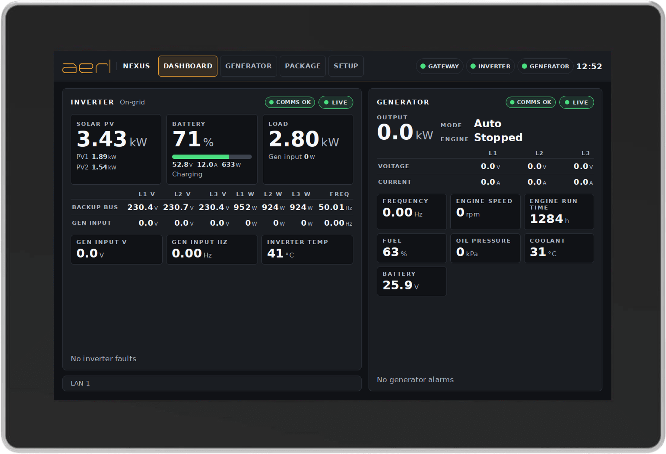
HMI-10 · NEXUS-HMI-10
Installation and Operation User ManualRev 1.0.0, 8 Nov 2026
Download PDF· Rev 1.0.0
Installation and Operation User Manual
10.1″ Sunlight-Readable Touch HMI
Australian Energy Research Laboratories (AERL) was founded in 1985 by Stuart Watkinson to commercialise the Power Optimizer, which he developed while studying at the University of Queensland. It became the AERL MAXIMIZER™, a universal maximum power point tracker (MPPT).
Today AERL designs, integrates and supports power conversion, lithium energy storage, monitoring and earth-fault detection products for commercial, industrial and off-grid energy systems, including oil and gas, mining and telecommunications sites.
AERL and the AERL logo are trademarks owned by AERL Holdings Pty Ltd and used by AERL Pty Ltd under licence. These trademarks may be registered in Australia and other countries. Solinteg, Deep Sea Electronics and other third-party names are trademarks of their respective owners; they are used here only to identify compatible equipment.
November 2026 (11/2026)
AERL Industrial HMI (HMI-10) User Manual © 2026 AERL Pty Ltd. All rights reserved.
UNLESS SPECIFICALLY AGREED TO IN WRITING, AERL PTY LTD:
(a) MAKES NO WARRANTY AS TO THE ACCURACY, SUFFICIENCY OR SUITABILITY OF ANY TECHNICAL OR OTHER INFORMATION PROVIDED IN ITS MANUALS OR OTHER DOCUMENTATION.
(b) ASSUMES NO RESPONSIBILITY OR LIABILITY FOR LOSS OR DAMAGE, WHETHER DIRECT, INDIRECT, CONSEQUENTIAL, OR INCIDENTAL, WHICH MIGHT ARISE OUT OF THE USE OF SUCH INFORMATION.
THE USE OF ANY SUCH INFORMATION WILL BE ENTIRELY AT THE USER'S RISK.
Australian Energy Research Laboratories, 1/75 Bluestone Circuit, Seventeen Mile Rocks QLD 4073, Australia
aerl.com.au · [email protected] · [email protected] · 1800 950 865
This manual contains important safety information and installation and operating instructions for the AERL Industrial HMI (HMI-10). It uses the following symbols for important operating information and potentially dangerous conditions.

Indicates information that must be followed to ensure proper installation or operation of the HMI-10.

Indicates a critical procedure for the safe installation or operation of the HMI-10 or the equipment it controls.
This manual covers installing the HMI-10, connecting it to the site's inverter and generator controller, and using its screens. Read all of its instructions and cautions before you start.
Only qualified electricians and technicians may install and commission the HMI-10. Site operators may use the Dashboard; the control and setup screens are protected by a PIN.
Do not disassemble or attempt to repair the HMI-10 unless you are a qualified technician and have authority in writing from AERL to do so.
AERL will not be held responsible in any way for the mishandling of this product or for installation of the product in a manner that does not follow the instructions in this manual or as advised by AERL.
The AERL Industrial HMI (HMI-10) is a 10.1″ sunlight-readable touch panel with the AERL Nexus software built in. It gives operators a local view of the site's inverter and generator, and gives authorised staff local control of both.
The HMI-10 is the local control point of the system. It reads the inverter and the generator controller over Modbus (Ethernet, with RS-485 as an option), shows their values on its screens, sends start, stop and mode commands, and serves the same data to the site's SCADA system over Modbus TCP.
| Equipment | How the HMI-10 connects |
|---|---|
| Solinteg M2HT inverter | Modbus TCP over Ethernet (default port 502), or Modbus RTU over RS-485 |
| Deep Sea Electronics DSE74xx MKII generator controller | Modbus TCP over Ethernet (unit ID 10), or Modbus RTU over RS-485 |
| Site SCADA | Modbus TCP server on the HMI-10 (read; package commands from allowed addresses only) |
The HMI-10 is the only Modbus client of the inverter and the generator controller. Do not connect another Modbus master to them.
| Screen | Access | What it is for |
|---|---|---|
| Dashboard | Open | Live inverter and generator values, faults and alarms |
| Generator | PIN | Generator mode (Auto, Manual), Start, Stop, Reset alarms, telemetry start |
| Package | PIN | Inverter package Start, Stop, Emergency stop, Clear emergency stop |
| Setup | PIN | Device links, SCADA server, Network, Quiet hours, Security |
| Parameter | Value |
|---|---|
| Diagonal size | 10.1 in |
| Resolution | 1280 × 800 (WXGA) |
| Panel type | IPS · normally black, transmissive |
| Luminance | 1000 cd/m² |
| Viewing direction | All |
| Touch panel | Capacitive · up to 10 touch points |
| Backlight | White LED · 30 000 h min. life |
| Parameter | Value |
|---|---|
| Input voltage | 12–24 Vdc (24 Vdc supplies need an in-line 12 V regulator; contact AERL) |
| Power consumption | 9.6 W typ. (static desktop, default brightness) |
| Parameter | Value |
|---|---|
| Processor | Rockchip RK3568 · quad-core Cortex-A55, 2.0 GHz · Mali-G52 GPU |
| Memory | 2 GB LPDDR4 |
| Storage | 32 GB eMMC · TF card slot |
| Operating system | Linux |
| Ethernet | 2 × 10/100/1000 |
| RS485 · CAN · RS232 | 2 × each (expansion IO header) |
| Wireless | Wi-Fi · Bluetooth · 4G LTE (nano SIM) |
| USB | 2 × USB-A · 1 × USB-C (OTG) |
| Video out | HDMI 1.4 |
| Parameter | Value |
|---|---|
| Dimensions (W × H × D) | 260.4 × 177.4 × 37 mm |
| Weight | 1.21 kg typ. |
| Enclosure | Full metal |
| Ingress protection | IP65 (front) |
| Operating temperature | −20 to 70 °C |
| Storage temperature | −30 to 80 °C |
| Mounting | Panel mount, or rear mount · 4 × M4 threaded holes, VESA 75 × 75 mm |
| Certifications | RoHS |
| Part number | NEXUS-HMI-10 (model HMI-10) |
| Warranty | 2 years |
All installations must comply with national and local electrical standards and codes of practice.
The HMI-10 mounts one of two ways:
For a rear mount, seal the window in the door so that the front of the HMI-10 stays dry. Contact AERL for the panel cut-out dimensions.
Check the polarity and the voltage at the HMI-10's input before you connect it. Applying more than the rated input voltage, or reversed polarity, may damage the unit and is not covered by the warranty.
The HMI-10 has two Ethernet ports, LAN 1 and LAN 2. One port is enough: the inverter, the generator controller and the SCADA system can all be on one switch connected to LAN 1. LAN 2 is optional.
Use shielded twisted-pair cable for RS-485 and keep data cables away from power cables.
When power is applied, the HMI-10 starts its software and then shows the Dashboard. Start-up can take up to about two minutes. The HMI-10 does not need an internet connection to start or to show the site's equipment.
Every screen has the same header:
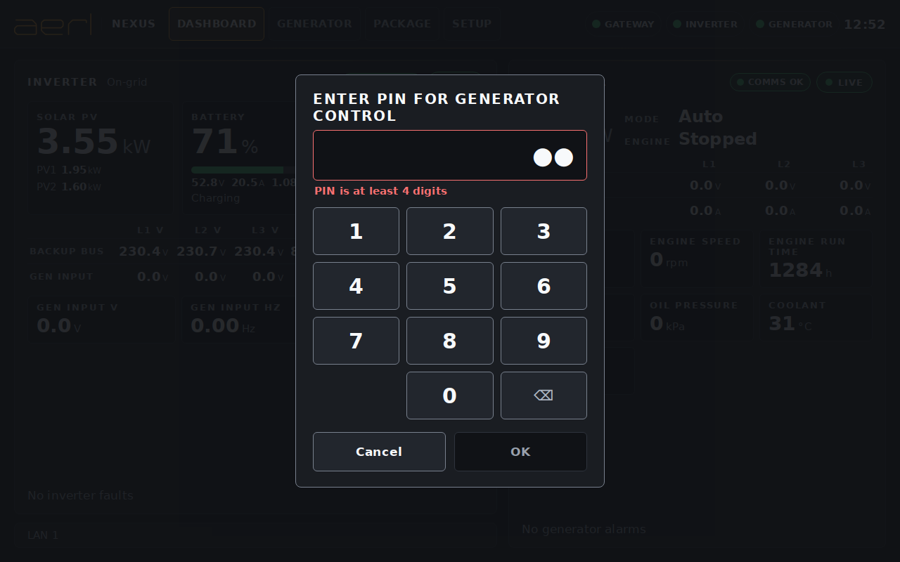
The HMI-10 is used by touch only; there is no keyboard or mouse. Numbers, addresses and PINs are entered on an on-screen numeric keypad. Touch a field to open the keypad, enter the value and touch OK, or Cancel to leave the value as it was.
The Dashboard is open to everyone. The Generator, Package and Setup screens ask for the PIN ("Enter PIN for Generator control", "Enter PIN for Package control", "Enter PIN for Setup").
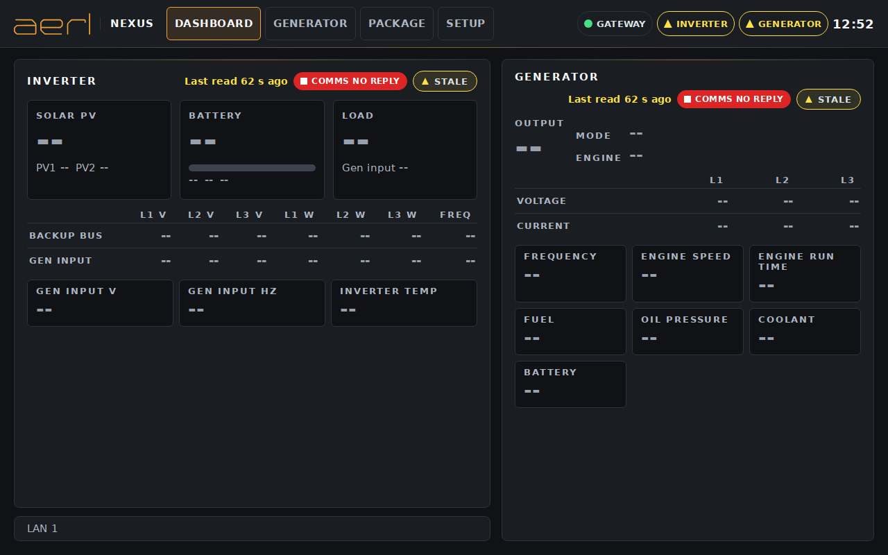
The Dashboard shows the live state of the inverter and the generator. It needs no PIN.
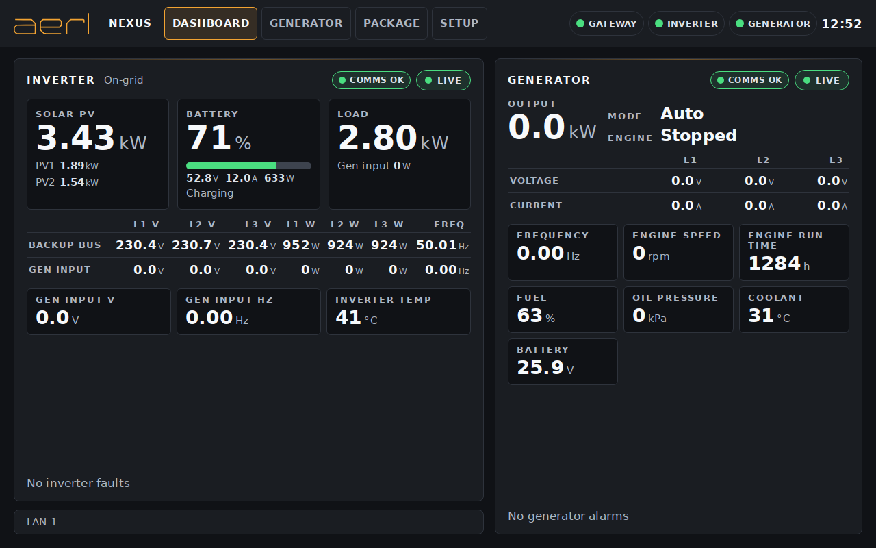
Each card has two pills in its top corner. The comms pill shows the state of the link to the device, for example Comms OK or Comms no reply. The data pill shows whether the values are Live or Stale, or that the link is down or disabled. When a device is running on its RS-485 fallback link, the card says so.
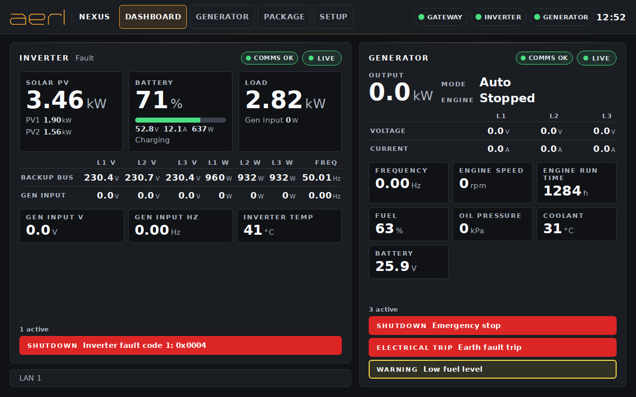
Alarms and faults are listed at the foot of each card, the most serious first: a solid red bar for a shutdown or an electrical trip, a yellow outline for a warning. When there are more than fit, the list says how many are active ("3 active, swipe to see all"): swipe the list to see the rest.
When the HMI-10 has not had a good reading from a device for longer than its stale limit, that device's values are shown greyed as "--", with the time of the last good reading ("Last read 62 s ago"). The screen keeps trying and shows live values again as soon as the device answers.
The Generator screen controls the generator through its controller. It needs the PIN.
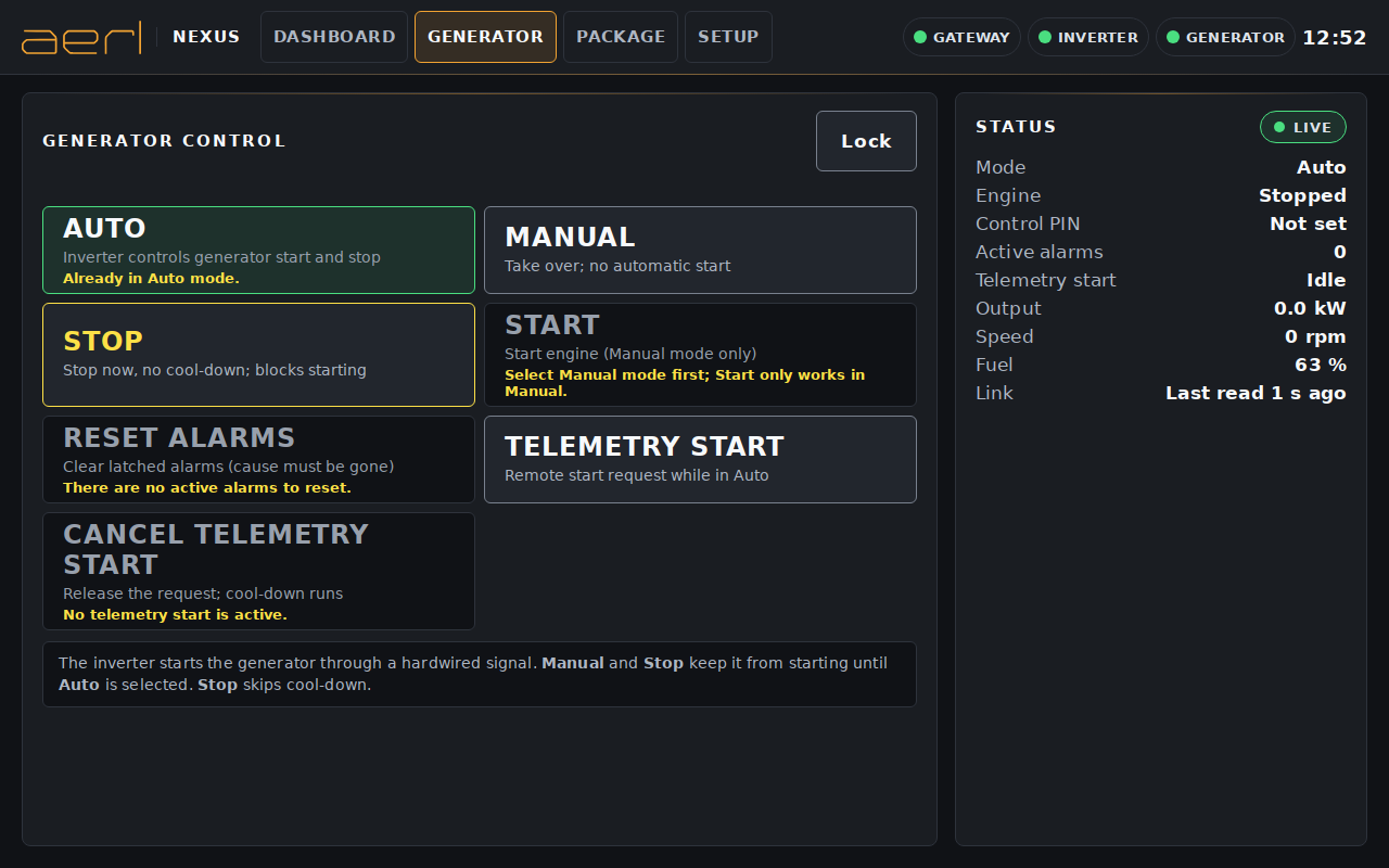
| Button | What it does |
|---|---|
| Auto | The inverter controls generator start and stop |
| Manual | Take over: no automatic start |
| Stop | Stop now, no cool-down; blocks starting |
| Start | Start engine (Manual mode only) |
| Reset alarms | Clear latched alarms (the cause must be gone) |
| Telemetry start | Remote start request while in Auto |
| Cancel telemetry start | Release the request; the cool-down runs |
Every command opens a confirmation that states its consequence, for example "Make sure the area around the generator is clear." before a start, or "Only reset after the cause has been checked." before an alarm reset. Touch the confirm button to send it.
The inverter starts the generator through a hardwired signal. Manual and Stop keep it from starting until Auto is selected again.
A command that cannot be sent is greyed, with the reason under it: for example "Already in Auto mode.", "Select Manual mode first; Start only works in Manual.", or "There are no active alarms to reset." Control is also unavailable while the generator's data is stale or disconnected, while generator panel control is switched off in Setup, or while the generator controller's control PIN is missing or has been rejected.
The panel beside the buttons shows the generator's Mode, Engine state, Control PIN state, Active alarms, Telemetry start, Output, Speed, Fuel and Link, and the result of the last command as the HMI-10 follows it (for example cranking, running up, running, or failed to start).
If a start is requested during quiet hours, the screen says "Quiet hours are active" and offers Start anyway or Do not start.
The Package screen starts and stops the inverter package. It needs the PIN, and package control must be switched on in Setup > SCADA server.
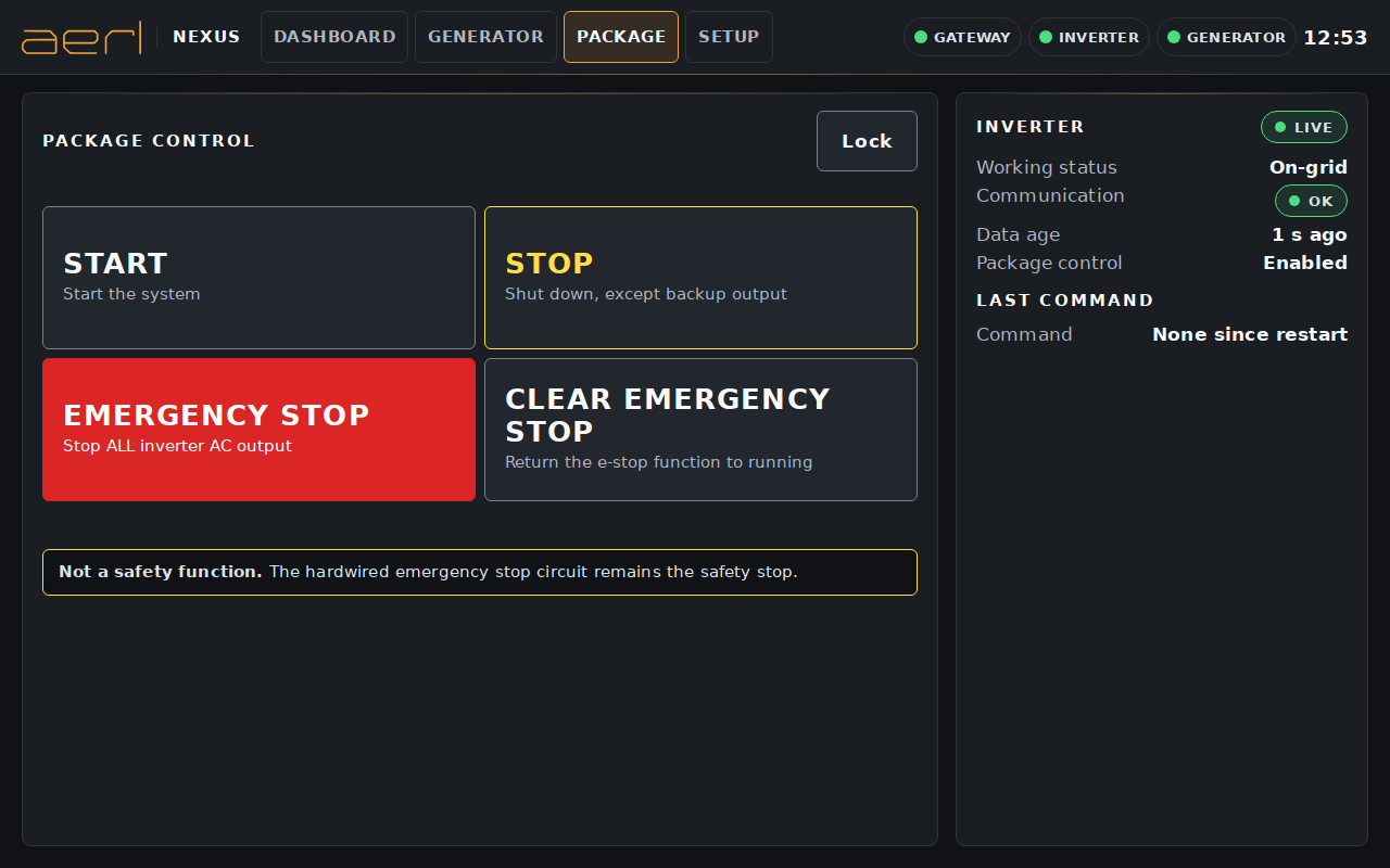
Package control is not a safety function. The hardwired emergency stop circuit remains the safety stop.
| Button | What it does |
|---|---|
| Start | Start the system. Confirm only when it is safe to energise the system. |
| Stop | Shut down, except backup output. The site supply may be affected. |
| Emergency stop | Stop ALL inverter AC output. You are asked to confirm twice ("Yes, emergency stop"). |
| Clear emergency stop | Return the e-stop function to running. |
The panel beside the buttons shows the inverter's Working status, Communication, Data age and whether Package control is Enabled, and the last command: its Counter, Command, Result (Accepted, Rejected by inverter, or No reply from inverter) and Source (SCADA, or This touchscreen).
A command that has no reply may or may not have been applied: check the inverter's working status before you send it again. The HMI-10 never repeats a command by itself.
Setup holds the HMI-10's settings. It needs the PIN. The menu on the left opens Inverter, Generator, SCADA server, Network, Quiet hours and Security.
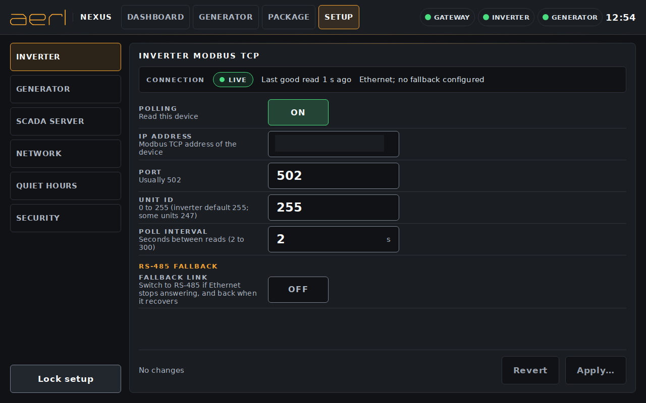
Changes you make form a draft ("Unsaved change"). Touch Apply to see the list of changes and confirm them, or Revert to discard them. The screen then shows "Settings applied", or "Not applied" if the change was not kept.
| Setting | Use |
|---|---|
| Polling | Read this device (On or Off) |
| Link | Ethernet, or RS-485 where the device offers it |
| IP address | The device's Modbus TCP address on the site network |
| Port | Usually 502 |
| Unit ID | Inverter: 0 to 255 (the inverter's default is 255; some units use 247). Generator: fixed at 10 over Ethernet; set at the controller on RS-485 |
| Setting | Use |
|---|---|
| Poll interval | Seconds between reads (2 to 300) |
| RS-485 fallback | On an Ethernet link: switch to RS-485 if Ethernet stops answering, and back when it recovers |
| RS-485 settings | Channel (0: A0, B0; 1: A1, B1), baud rate and unit ID; 8 data bits, no parity, 1 stop bit |
The generator page also has:
The HMI-10 serves the inverter, generator and HMI-10 status to the site SCADA system as a Modbus TCP server.
Contact AERL for the SCADA register map.
Set the address of each port, LAN 1 or LAN 2: DHCP (the default) or Static with an IP address, netmask, gateway and up to two DNS servers. The gateway is needed for remote support.
A network change is on trial: after you apply it, the HMI-10 checks the new setting and undoes it by itself after 2 minutes unless you touch Keep. Touch Undo to go back straight away. This keeps a wrong address from cutting the HMI-10 off its network.
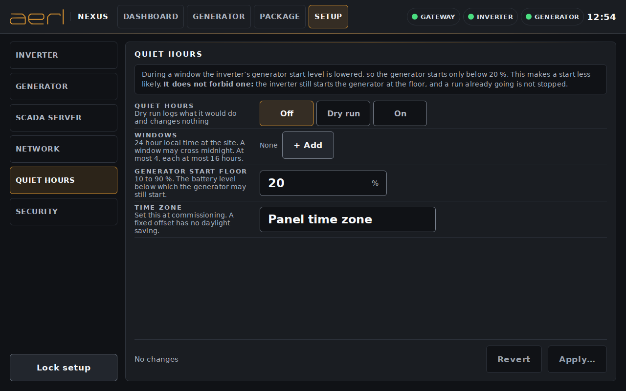
During a quiet-hours window the inverter's generator start level is lowered, so the generator starts only below the generator start floor. This makes a start less likely. It does not forbid one: the inverter still starts the generator at the floor, and a run already going is not stopped.
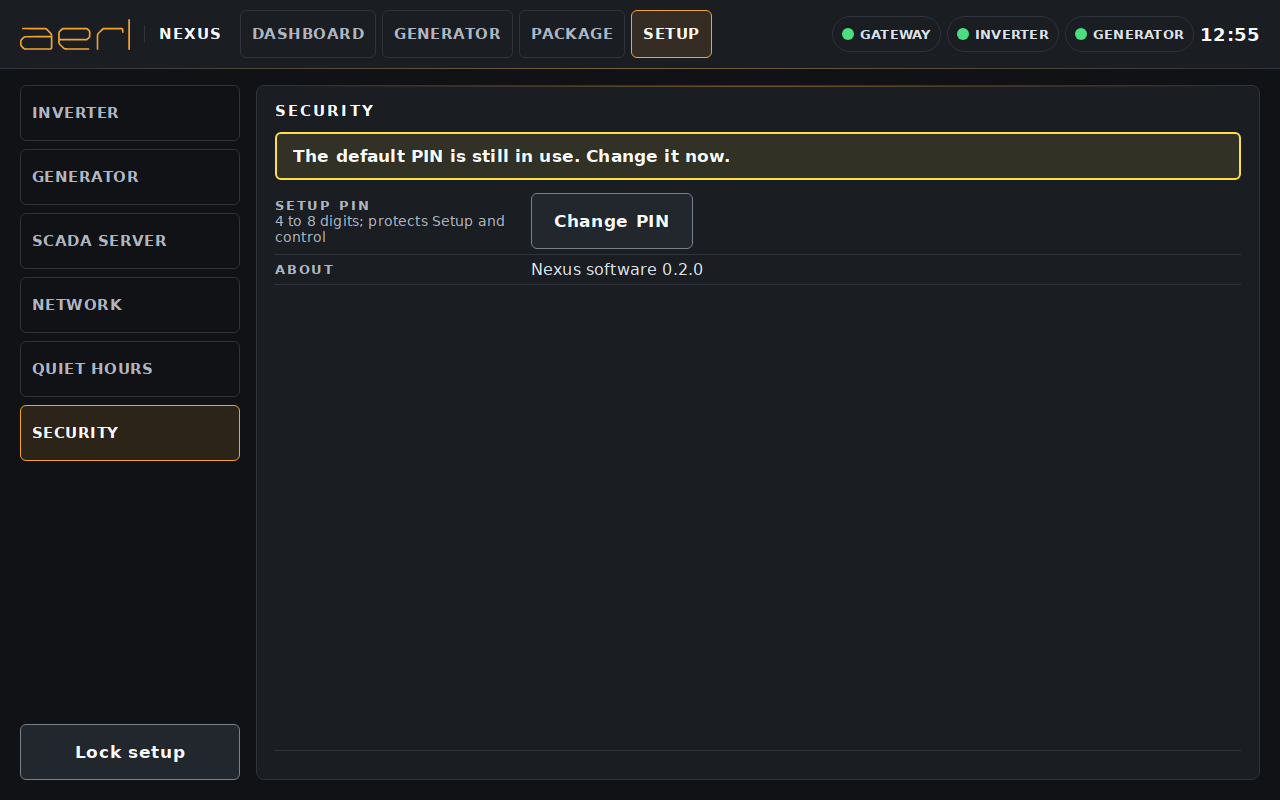
Change the Setup PIN here: enter the current PIN, then the new PIN twice. Until the default PIN is changed, the page shows "The default PIN is still in use. Change it now." The About line shows the software version (for example "Nexus software 0.2.0"): quote it when you contact AERL.
The HMI-10 shows a banner across the top of the screen when something is wrong. It keeps trying in the background and recovers by itself when the cause is fixed.
| What the screen shows | What to do |
|---|---|
| "The screen has lost contact with the Nexus. Retrying… Values below are not live." | The HMI-10's own software is restarting. Wait a minute. If it stays, switch the HMI-10 off and on again. |
| "The gateway is not responding. Waiting for it to come back…" | As above. If it stays after a restart, contact AERL support. |
| "Settings cannot be read from the gateway." | Wait a minute and open Setup again. If it stays, contact AERL support. |
| "Inverter: Ethernet and RS-485 links are both down." (or Generator) | Check the device has power, the Ethernet cable and switch, the RS-485 wiring, and the device's IP address, port and unit ID in Setup. |
| Values greyed as "--", "Last read … ago", Stale pill | The device is not answering. Check its power, cabling and the link settings in Setup. |
| Comms no reply pill | Check the IP address, port and unit ID in Setup against the device's own settings. |
| Generator buttons greyed | Read the reason under each button. Check that panel control is on (Setup > Generator), that the Control PIN is Accepted, and that the generator's data is live. |
| Control PIN Rejected or Locked out | Enter the correct generator controller PIN in Setup > Generator. After a lock-out, wait for it to clear before you try again. |
| Package buttons greyed | Switch on package control (Setup > SCADA server), and check that the inverter's data is live. |
| "Package control is not available." or "This Nexus does not offer package control yet. A software update is needed." | Generator and package control are enabled by AERL when the site is commissioned, and some sites need a Nexus software update first. Contact AERL support. |
| "Session expired. Enter PIN again." | Enter the PIN again. |
| Lost network access after a network change | Touch Undo, or wait 2 minutes: the previous setting is restored by itself unless you touched Keep. |
If your situation is not covered here, contact AERL support on 1800 950 865 or at [email protected]. Have the HMI-10's serial number, the software version (Setup > Security) and a photo of the screen ready.
The HMI-10 has a 2-year warranty. It starts 30 days after AERL dispatches the HMI-10, or on the day it first connects to AERL Cloud if that is sooner.
Register your HMI-10 at aerl.com.au/warranty-registration. Registration does not change the 2-year warranty.
Our goods come with guarantees that cannot be excluded under the Australian Consumer Law. You are entitled to a replacement or refund for a major failure and compensation for any other reasonably foreseeable loss or damage. You are also entitled to have the goods repaired or replaced if the goods fail to be of acceptable quality and the failure does not amount to a major failure.
The full terms and the claim procedure are in the AERL Industrial HMI (HMI-10) Warranty Statement, at aerl.com.au.
| Revision | Date | Change |
|---|---|---|
| 1.0.0 | 11 / 2026 | First issue. |
If you have any questions or need support, contact AERL.
Sincerely,
The AERL Team
AERL Pty Ltd · 1/75 Bluestone Circuit, Seventeen Mile Rocks QLD 4073 · 1800 950 865 · [email protected] · aerl.com.au
Australian Energy Research Laboratories
1/75 Bluestone Circuit
Seventeen Mile Rocks QLD 4073
Australia