 Download PDF· Rev 2.0.1
Installation Guide
Kakadu Combiner Box
Mounting, Cable Preparation and Power Termination
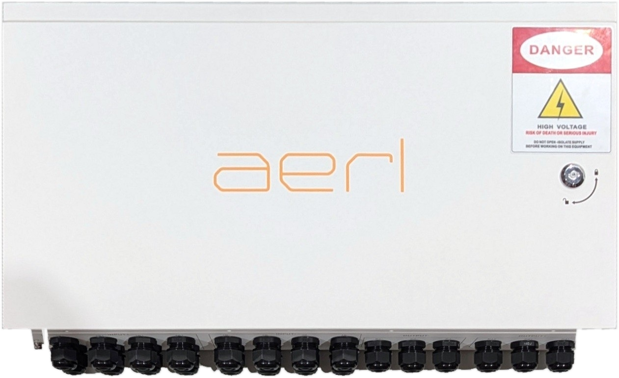
KAKADU-COMB · Kakadu 120
Installation GuideRev 2.0.1, 8 Nov 2026
Download PDF· Rev 2.0.1
Installation Guide
Mounting, Cable Preparation and Power Termination
This guide shows how to mount an AERL Kakadu Combiner Box, prepare its cable entries, and terminate the battery and load power cables ready for commissioning.
The Kakadu Combiner Box is the companion combining enclosure for the AERL Kakadu 120 battery cabinet. It parallels the DC output of up to four Kakadu 120 cabinets onto a common busbar and presents a combined output to the inverter or load equipment.
| Parameter | Rating |
|---|---|
| Maximum voltage | 500 V DC |
| Maximum input current | 150 A |
| Maximum output current | 250 A |
| Terminal torque | M8 · 13 N·m |
| Ingress protection | IP55 |
| Dimensions (W × H × D) | 750 × 400 × 132 mm |
| Weight | 18 kg ±5% |
| Maximum cabinets supported | 4 × Kakadu |
| Busbar | 3 × 25 mm · 75 mm² |
| Mandatory input protection | 150 A DC MCB or 150 A HRC fuse, per input |
| Mandatory output protection | 250 A DC MCB or 250 A HRC fuse, per output |
| Recommended cable — battery side | 50 mm² with SC50-8 lugs |
| Recommended cable — inverter side | 70 mm² with SC70-8 lugs |
| Application | 1 × SPLC1202 per output |
The gland plate provides eight battery input pairs (1B to 8B). Each Kakadu cabinet presents two pairs of positive and negative terminals, so the enclosure combines a maximum of four Kakadu cabinets.
Three output pairs (P1 to P3) are provided for the connection to the inverter or load equipment. Internal busbars are 3 mm × 25 mm, giving a cross-sectional area of 75 mm². Internal fusing is for short circuit protection only. Overcurrent protection shall be installed to protect both cables and bus bar.
The combiner box is designed for a three-phase Selectronic SP PRO SPLC1202 system, or similar. The three outputs allow one connection to each inverter.
The Kakadu Combiner Box carries the full combined battery current and is a live DC busbar assembly rated to 500 V DC. Read this chapter before opening the enclosure.
Installation, termination and commissioning must be carried out only by a licensed electrical worker competent in battery energy storage systems, and must follow AS/NZS 3000 and AS/NZS 5139.
This enclosure is rated to 500 V DC and must be treated as low-voltage DC throughout. Apply low-voltage isolation, signage and access-restriction requirements in accordance with AS/NZS 3000.
The Kakadu 120 is a 140.8 V nominal battery. Establish the actual bank voltage for the system in front of you before starting work.
A short circuit across the combined busbar will not self-extinguish the way an AC fault does, and the severity rises sharply with system voltage. A sustained DC arc is a life-threatening hazard, not an equipment-damage risk.
Use insulated tools rated for the system voltage, remove watches and rings, and never leave a loose lug, washer or dropped fastener inside the enclosure.
Refer to AS/NZS 5139:2019 for guidance on arc flash hazard.
Select PPE in accordance with AS/NZS 5139:2019 Clause 3.2.4 and Clause 3.2.4.4. As a minimum this will include insulated gloves rated for the full system voltage, eye or face protection, and arc-rated clothing appropriate to the assessed hazard. Do not work alone on an energised bank.
Unpack the combiner box and confirm all items are present and undamaged before starting. Report any transit damage to AERL before installation.
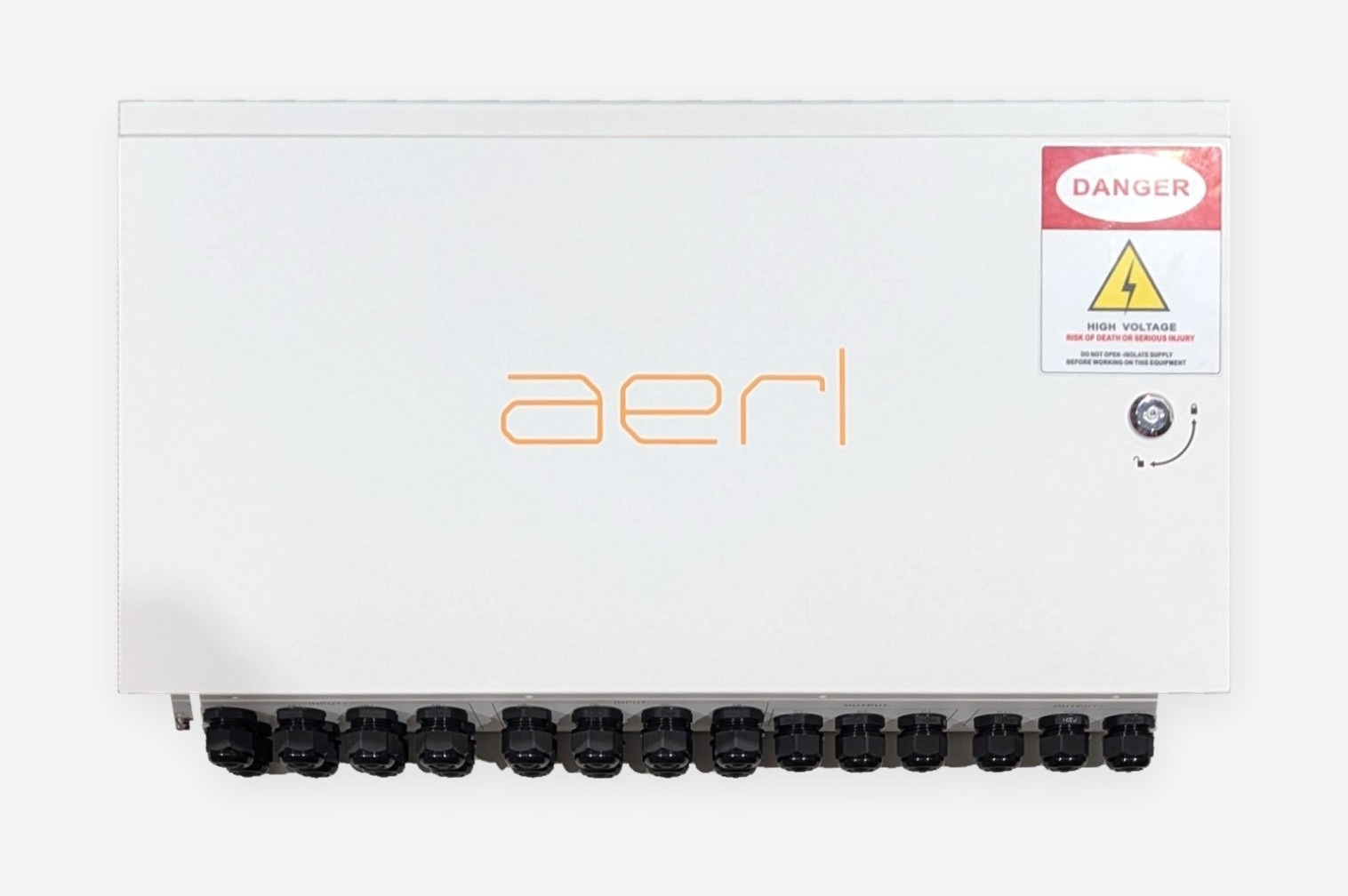
| Item | Qty | Notes |
|---|---|---|
| Kakadu Combiner Box | 1 | Front view shown in closed state |
| Combiner box key | 1 | Required to open the door — keep with the system documentation |
| Expansion bolts | 4 | Wall fixings, one per mounting point |
Use a two-person lift when mounting the enclosure.
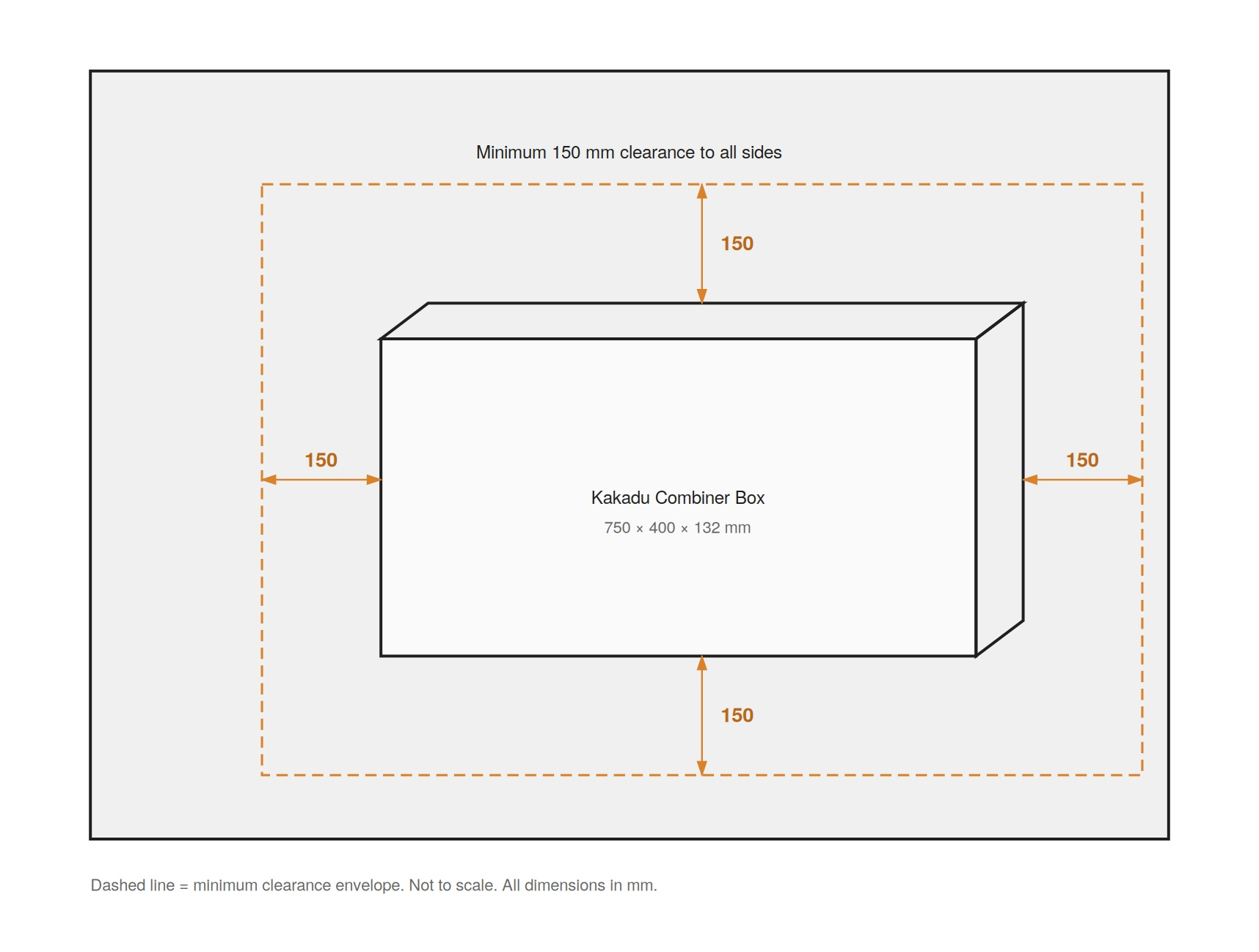
The enclosure measures 750 × 400 × 132 mm (W × H × D), weighs 18 kg ±5% and is rated IP55 — protected against dust and against water jets from any direction.
Choose a location that is:

Do not install in coastal areas subject to salt mist.
Mark four mounting points on the wall at a recommended height of 1.0–1.5 m above the ground, with a spacing of 773 × 250 mm.

The enclosure body is 750 mm wide, but the horizontal fixing centres are 773 mm. The fixings therefore sit 11.5 mm outboard of each side of the body, on the mounting brackets — not on the back panel within the footprint.
Use a spirit level to check the enclosure is level.
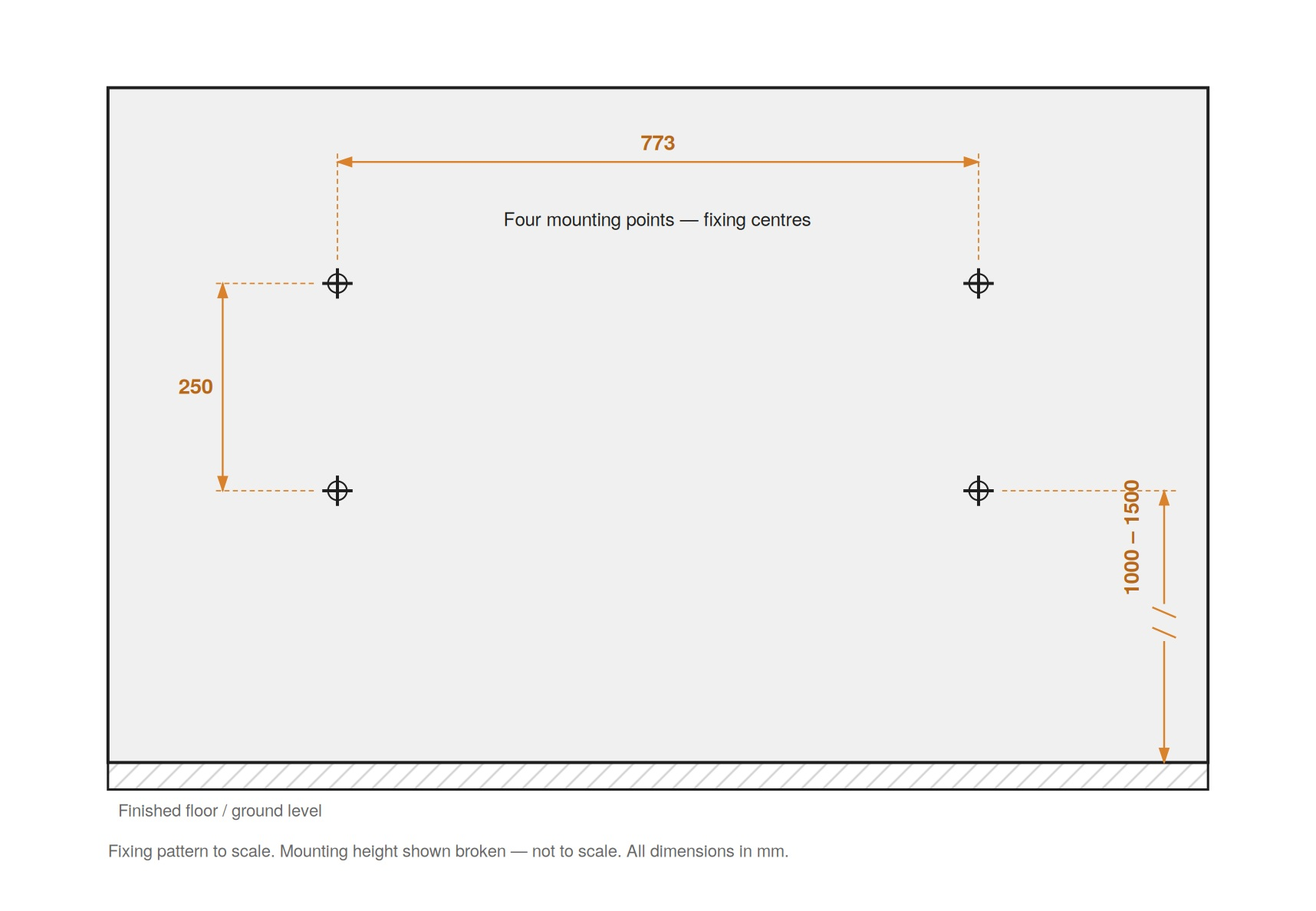
Position the combiner box against the wall and check that the marked hole locations line up with the enclosure's mounting points.
Drill the four mounting holes, insert the supplied expansion bolts — or a suitable alternative fixing appropriate to the mounting substrate — and fasten the combiner box securely to the wall.
Check the enclosure is level once more after tightening, and confirm all four fixings are loaded evenly.
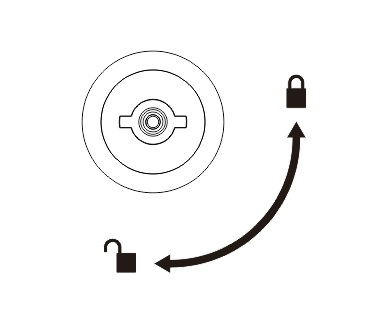
Use the supplied key to unlock the enclosure door.
Open the door fully and support it while working.
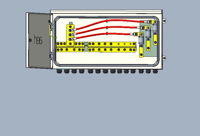
Before touching anything inside, re-confirm the isolation and prove dead at the busbars per Chapter 01.
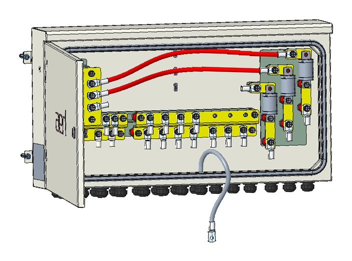
Remove the lock nuts fitted with the PG cable glands required for the cable installation, and remove only the M8 terminal bolts required, depending on the number of systems being combined.
Leave any unused glands and terminal bolts in place. All unused entries must stay sealed and vermin-proof.
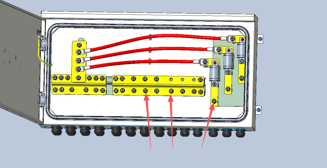
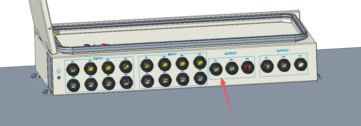
Keep the removed hardware together and in a tray. A loose M8 bolt left in the base of the enclosure is a short-circuit waiting for the first vibration.
The recommended conductor sizes and lugs are:
| Circuit | Conductor | Lug |
|---|---|---|
| Battery side — B+ / B−, input pairs | 50 mm² | SC50-8 |
| Inverter side — P+ / P−, output pairs | 70 mm² | SC70-8 |
The selected cable must meet the requirements of AS/NZS 5139.

All power cables must be passed through the waterproof cable glands before the cable lugs are crimped. A crimped lug will not pass through the cable gland. Getting this out of order means cutting the lug off and re-terminating.
Work in this order for every conductor, without exception:
Tighten each gland onto the cable once the conductor is in its final position, so the gland grips the sheath and not the insulation of a strained cable.
Crimp cable lugs onto the power cables. All cable lugs are secured using M8 bolts, torqued to 13 N·m on final assembly (see Chapter 07).
Crimp with the correct die for the lug, apply the full number of crimps for the barrel length, and finish each barrel with adhesive heat-shrink. Confirm every crimp with a pull test before installing the cable.
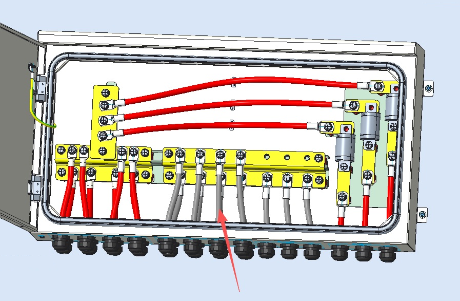
Connect all B+, B−, P+ and P− power cables to their designated entry positions and terminals.
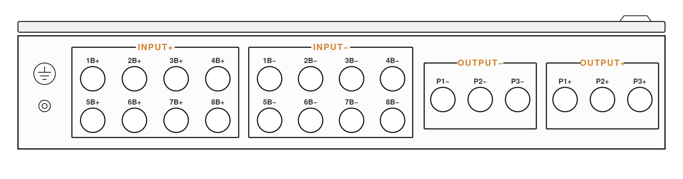
The gland plate is divided into four labelled groups:
| Group | Positions | Function |
|---|---|---|
| INPUT+ | 1B+ to 8B+ | Battery positive — two positions per Kakadu cabinet |
| INPUT− | 1B− to 8B− | Battery negative — two positions per Kakadu cabinet |
| OUTPUT+ | P1+, P2+, P3+ | Combined positive to the load / inverter |
| OUTPUT− | P1−, P2−, P3− | Combined negative to the load / inverter |
An earth point is provided at the left-hand end of the plate.
Each combiner input must be protected by a 150 A DC MCB or a 150 A HRC fuse, fitted on the battery feed upstream of the combiner. Each combiner output must be protected by a 250 A DC MCB or a 250 A HRC fuse, fitted on the inverter feed downstream of the combiner.
Each output supplies a maximum of one Selectronic SP PRO SPLC1202. Do not connect a load with >250 A continuous current rating.
| Duty | Device | Location |
|---|---|---|
| Short circuit | Combiner's internal fuse | Busbar origin, inside the enclosure |
| Overload | Kakadu BMS DC MCB | Battery Output, upstream |
| Overload | 150 A DC MCB or 150 A HRC fuse | Each battery input, upstream |
| Overload | 250 A DC MCB or 250 A HRC fuse | Inverter feed, downstream |
Note: The combiner's internal fuse cannot provide overload protection for the busbar — its rating is far above the busbar's continuous rating. The downstream device carries the whole of the busbar's load current and is what protects it against overload. Omitting it leaves the busbar without overload protection.
AS/NZS 4509, AS/NZS 5139 and the manufacturer's guidelines must be followed for electrical protection.
Working practice at the busbar:
Complete these checks before the bank is energised.
Refer to the Kakadu 120 Installation and Operating Manual for the start-up and shutdown sequence.
| Step | |
|---|---|
| 1 | Isolate and prove dead with an instrument rated for the full system voltage. Lock out every isolation point. |
| 2 | Confirm package contents: combiner box, key, 4 × expansion bolts. |
| 3 | Mark four mounting points, 1.0–1.5 m above ground, 773 × 250 mm spacing. |
| 4 | Offer the box up and verify hole positions before drilling. Two-person lift — 18 kg. |
| 5 | Drill, fit expansion bolts, fasten the box level and secure on all four fixings. |
| 6 | Unlock and open the door. Re-check dead at the busbars. |
| 7 | Count the pairs needed — two per cabinet — then remove only the required lock nuts and M8 bolts. |
| 8 | Pass every cable through its gland before crimping any lug. |
| 9 | Crimp lugs sized to the designer's cable schedule. |
| 10 | Terminate B+, B−, P+ and P− per the gland plate layout. Torque M8 to 13 N·m and torque-seal. |
| 11 | Confirm a 150 A DC MCB or 150 A HRC fuse fitted on every input in use, and a 250 A DC MCB or 250 A HRC fuse on every output in use. |
| 12 | Verify polarity, clear the enclosure, insulation test, close and lock. |
| 13 | Refer to the Kakadu 120 Installation and Operating Manual for the start-up and shutdown sequence. |
The Kakadu Combiner Box warranty is 2 years, starting 30 days after AERL dispatches the product. Conditions apply: see the Kakadu 120 Battery and Combiner Box Warranty Statement, at aerl.com.au.
Before you contact AERL, note the number of Kakadu cabinets combined, the inverters connected and what the Kakadu HMI shows. Contact AERL support on 1800 950 865 or [email protected].
| Revision | Date | Change |
|---|---|---|
| 2.0.0 | 09 / 2026 | First release. |
| 2.0.1 | 11 / 2026 | Re-issued in the new AERL document design. Steps 6 and 7 put in working order (cables through the glands before the lugs are crimped, as the Important note and the quick checklist require); AS/NZS 5139 added to who may install; the Kakadu 120 manual named by its title; checklist items numbered in sequence; warranty term added; the mandatory 150 A input protection (Ratings) added to Step 9 and both checklists; text limited to the Kakadu 120. |
If you have any questions or need support, contact AERL.
Sincerely,
The AERL Team
AERL Pty Ltd · 1/75 Bluestone Circuit, Seventeen Mile Rocks QLD 4073 · 1800 950 865 · [email protected] · aerl.com.au
Australian Energy Research Laboratories
1/75 Bluestone Circuit
Seventeen Mile Rocks QLD 4073
Australia