Kakadu with Selectronic SP PRO SPLC1202 & AERL CoolMax SRX
Control Philosophy, Hardware, Connections and SP LINK Set-Up
AERL Kakadu · Rev 1.1.6
Revision1.1.6
Effective11 / 2026
AudienceLicensed electrical workers
BatteryKakadu 120 (managed)
InverterSP PRO SPLC1202
Charge controllerCoolMax SRX 120
EMSAERL Nexus Gateway
SP LINK battery typeBMS – SelectCell River Gum
CAN cable at SP PROSP PRO to BMS cable
SoC sourceKakadu BMS via CAN
CAN busSP PRO → Nexus → SRX → Kakadu
Nexus → SP PROCAN + RS485 Modbus RTU
In This Guide
01Control PhilosophyNexus as EMS, managed battery, roles03
02Required HardwareBill of materials, SP PRO prerequisites05
03ConnectionsConnection table, system examples, SP PRO to BMS cable06
04Set-UpNexus, EMS firmware, SRX set-up, SP PRO Modbus settings10
05AERL Technical SupportContact details, what to send13
AERL Kakadu · Commissioning Guide
Commissioning GuideRev 1.1.68 Nov 2026
Introduction
This guide covers the system-level commissioning of a Kakadu 120 battery bank operating with Selectronic SP PRO SPLC1202 inverters and AERL CoolMax SRX 120 DC-coupled MPPT charge controllers. It sets out AERL's recommended control philosophy, the hardware required, how the communications are connected, and the settings to program into the Nexus and the SP PRO.
It does not replace the product manuals. Install each item in accordance with its own documentation first.
Reference Documents
Document
Use it for
AERL Kakadu 120 Installation and Operating Manual, V1.1.1
Cabinet installation, BMS chain, Master Unit / Last Unit settings
Nexus wiring, getting online, claiming, adding the SP PRO
Selectronic SP PRO Manual (OI0003, Rev 47)
Inverter installation and operation
Selectronic SP LINK Manual (OI0005, Rev 31)
SP LINK configuration settings
Who may commission this system
Installation, termination and commissioning must be carried out only by a licensed electrical worker competent in battery energy storage systems, in accordance with AS/NZS 3000 and AS/NZS 5139.
What has changed
Since Rev 1.0.0 the SP PRO runs the Kakadu as a managed battery (battery type BMS – SelectCell River Gum); the Rev 1.0.0 Custom battery settings and SP LINK configuration file no longer apply. Cables made to Rev 1.1.5 or earlier used the wrong BMS-end CAN pins (now 4 and 5, section 3.4) — check them.
AERL Kakadu · Commissioning Guide
Commissioning GuideRev 1.1.68 Nov 2026
Chapter 01
Control Philosophy
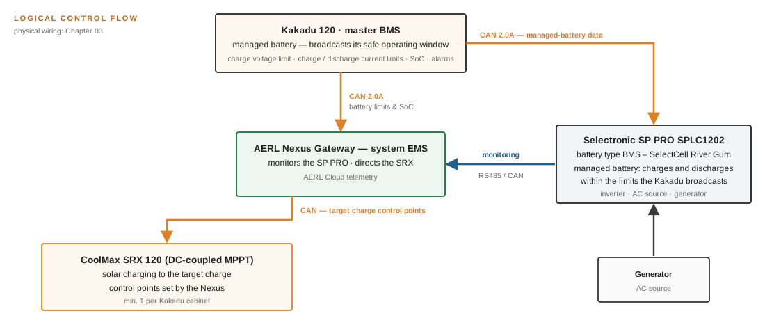
AERL recommends the following control philosophy for the Kakadu battery.
The AERL Nexus Gateway is the EMS for the entire system.
The Kakadu is a managed battery. Its master BMS broadcasts the battery's safe operating window over CAN bus.
The SP PRO SPLC1202 runs the Kakadu as a managed battery, with SP LINK battery type BMS – SelectCell River Gum. It reads the Kakadu's CAN data directly, and the SelectCell River Gum profile applies the correct voltage and charge settings.
The Nexus monitors the SP PRO and sends target charge control points to the CoolMax SRX.
The CoolMax SRX charges from solar to the target charge control points set by the Nexus.
Figure 1.1 Logical control flow. The Kakadu broadcasts its limits on the CAN bus. The SP PRO operates within them, and the Nexus monitors the SP PRO and directs the SRX.
AERL Kakadu · Commissioning Guide
Commissioning GuideRev 1.1.68 Nov 2026
Roles
Component
Role in the system
Link
Kakadu 120 master BMS
Managed battery. Broadcasts the safe operating window: charge voltage limit, charge and discharge current limits, SoC and alarms.
CAN 2.0A
SP PRO SPLC1202
Inverter, AC source management and generator charger. Managed battery type BMS – SelectCell River Gum. Charges and discharges within the Kakadu's limits.
CAN 2.0A (end of the bus). RS485 Modbus RTU to the Nexus
AERL Nexus Gateway
System EMS. Monitors the SP PRO and sends target charge control points to the SRX. Telemetry to AERL Cloud.
CAN (mid-bus). RS485 Modbus RTU to the SP PRO (Nexus is the only master)
CoolMax SRX 120
DC-coupled solar charging to the Nexus target charge control points
CAN
Generator
AC source for the SP PRO
Started by the SP PRO according to its Generator Auto Start settings
State of Charge
With a managed battery type, the SP PRO takes the battery SoC directly from the Kakadu BMS. No SP PRO DC shunt is needed on the SRX output.
AERL Kakadu · Commissioning Guide
Commissioning GuideRev 1.1.68 Nov 2026
Chapter 02
Required Hardware
2.1 Bill of Materials
Item
Quantity
Notes
AERL Nexus Gateway
1 per system
One Nexus covers the whole site. Do not put a second gateway, data logger or remote screen on the same SP PRO Modbus link.
AERL CoolMax SRX 120
Minimum 1 per Kakadu cabinet
Size the PV array for each SRX according to its datasheet.
AERL Kakadu 120 cabinet
1 to 16
Two strings (two BMS) per cabinet
Selectronic SP PRO SPLC1202
As designed
For example, 1 for single-phase or 3 in PowerChain for three-phase
AERL Kakadu Combiner Box
As required
Parallels up to 4 cabinets, with one output per SPLC1202. See the Combiner Box guide.
RS485 patch lead
1
Straight-through CAT5e or CAT6, Nexus RS485 to SP PRO ACC Port 1. Keep it short.
SP PRO to BMS cable
1
SP PRO CAN socket to Nexus CAN 2. Not a straight-through lead (section 3.4).
CAN leads
1 per hop
Shielded CAT5e or CAT6, made to length: Nexus → SRX → … → Kakadu master BMS INV
CAN termination
—
No terminator plugs needed. The Kakadu BMS terminates automatically, the SP PRO uses a DIP switch on its comms card, and each SRX has a CANBUS 120 Ω switch (section 3.1).
Ethernet lead
1
Nexus ETH to the site router
Laptop with Selectronic SP LINK
1
Must be a version of SP LINK that lists the battery type BMS – SelectCell River Gum
2.2 SP PRO Prerequisites
Check the following in SP LINK under Data View → Inverter Details before you connect the Nexus.
#
Requirement
1
The inverter is a Series 2i, or an equivalent newer model.
2
The Comms Card (ACC) revision is 8 or higher.
3
The SP PRO firmware is V14.47 or newer.
4
The ACC firmware is V4.31 or newer.
5
SP LINK offers BMS – SelectCell River Gum under Battery Type. If it does not, update SP LINK and the SP PRO firmware before you continue.
EMS firmware
The Nexus Gateway and every CoolMax SRX must run AERL's EMS firmware for this control philosophy. AERL installs it remotely during commissioning (section 4.1.2).
AERL Kakadu · Commissioning Guide
Commissioning GuideRev 1.1.68 Nov 2026
Chapter 03
Connections
Two communication links make up the control system.
CAN bus (CAN 2.0A): SP PRO → Nexus → CoolMax SRX → Kakadu
RS485 (Modbus RTU): Nexus → SP PRO, for monitoring
From
To
Link
Cable
Notes
SP PRO CAN
Nexus CAN 2
CAN 2.0A
SP PRO to BMS cable (section 3.4)
The SP PRO is one end of the bus: set the CAN termination DIP switch on its comms card to ON. On a PowerChain system, connect to the master only.
Nexus CAN 1
CoolMax SRX (last in chain) CAN
CAN 2.0A
Shielded CAT5e/CAT6
Nexus CAN 1 and CAN 2 are linked internally and the Nexus has no built-in termination. Here it sits mid-bus, so fit no termination plug.
CoolMax SRX CAN
Next CoolMax SRX CAN
CAN 2.0A
Shielded CAT5e/CAT6
Daisy-chain every SRX on the same bus. Set the CANBUS 120 Ω switch on every SRX to OFF.
CoolMax SRX (first in chain) CAN
Kakadu master BMS INV
CAN 2.0A
Shielded CAT5e/CAT6
The other end of the bus. The Kakadu BMS terminates automatically.
BMS OUT
Next BMS IN
Kakadu BMS chain
Made to length
See Kakadu 120 manual, step 7 and §5.5.
Nexus RS485
SP PRO ACC Port 1
RS485 · Modbus RTU
Straight-through CAT5e/CAT6
Slave 1, 9600 baud, 8N1. The Nexus is the only Modbus master. On a PowerChain system, connect to the master only.
Nexus ETH
Site router
Ethernet
CAT5e/CAT6
Connects automatically to AERL Cloud
3.1 Rules for the Communications Wiring
One CAN bus. The Kakadu, the SRX units, the Nexus and the SP PRO share a single CAN bus. Its order is SP PRO → Nexus → SRX → Kakadu.
CAN bus termination. The two ends of the bus are the SP PRO and the Kakadu master BMS, and each needs 120 Ω termination. Nothing in between should be terminated.
Device
Position on the bus
Termination setting
SP PRO (PowerChain master)
End
CAN termination DIP switch on the comms card ON
AERL Nexus Gateway
Mid-bus
None (no built-in termination; at a bus end, fit a 120 Ω plug in its spare CAN socket)
CoolMax SRX (every unit)
Mid-bus
CANBUS 120 Ω switch OFF
Kakadu master BMS
End
Automatic — nothing to set
AERL Kakadu · Commissioning Guide
Commissioning GuideRev 1.1.68 Nov 2026
Master BMS. The BMS whose INV port connects to the CAN bus is the master. Leave its Master Unit LED lit and turn it off on every other BMS. Leave Last Unit lit on the final string in the chain only (Kakadu 120 manual §6.3 and §6.4).
PowerChain master only. On a PowerChain system, connect the CAN bus and the RS485 lead to the PowerChain master only. The other inverters receive battery data over Selectronic's PowerChain link.
Cabling practice. Mount the Nexus as close as possible to the SP PRO, so that the RS485 run is short. Use shielded CAT5e/CAT6 for CAN, with the shield earthed at one end only. Keep comms cables separated from DC power runs. Contact AERL for any CAN run longer than about 100 m.
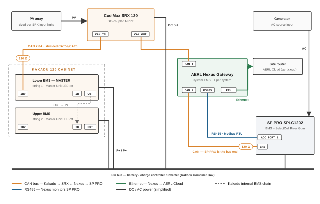
Figure 3.1 One Kakadu 120 cabinet, one CoolMax SRX 120, one SP PRO SPLC1202 and one Nexus Gateway. The CAN bus runs from the master BMS INV port through the SRX and the Nexus to the SP PRO. RS485 runs from the Nexus to ACC Port 1.
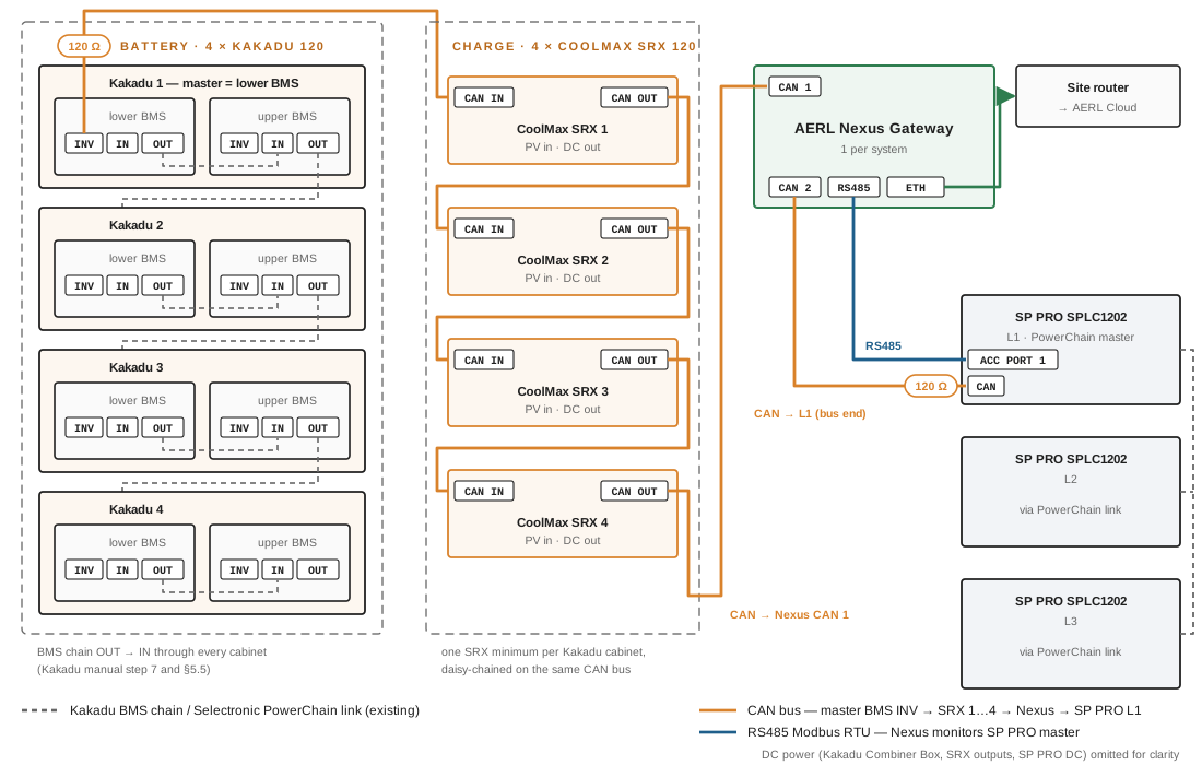
Figure 3.2 Four cabinets (8 BMS) through one Kakadu Combiner Box to a three-phase PowerChain of SPLC1202s. The CAN bus runs master BMS INV → SRX 1 → SRX 2 → SRX 3 → SRX 4 → Nexus → SP PRO L1. The same pattern scales to 16 cabinets, with at least one SRX per cabinet.
3.4 SP PRO to BMS Cable
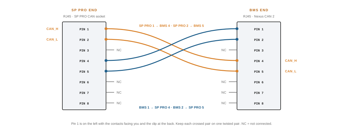
The SP PRO and the Kakadu BMS use different RJ45 pins for CAN. Connect the SP PRO to the CAN bus with the SP PRO to BMS cable, which re-maps the pins. A standard straight-through patch lead will not work.
Plug the SP PRO end into the SP PRO CAN socket (the PowerChain master on a PowerChain system). Plug the BMS end into Nexus CAN 2.
SP PRO end — pin
SP PRO end — signal
BMS end — pin
BMS end — signal
1
CAN_H
4
CAN_H
2
CAN_L
5
CAN_L
4
—
1
—
5
—
2
—
3, 6, 7, 8
—
Not connected
—
AERL Kakadu · Commissioning Guide
Commissioning GuideRev 1.1.68 Nov 2026
Pins 1/2 at each end cross to pins 4/5 at the other end, as shown in Selectronic's BMS to SP PRO CAN Bus cable application note. The cable is symmetrical and works either way round. CAN_H / CAN_L are on pins 1 / 2 at the SP PRO and on pins 4 / 5 at the Nexus CAN 2 socket.
Figure 3.3 SP PRO to BMS cable pinout, both directions.
If you make the cable up yourself, keep CAN_H and CAN_L on one twisted pair, and check every pin for continuity against the table before you fit it.
AERL Kakadu · Commissioning Guide
Commissioning GuideRev 1.1.68 Nov 2026
Chapter 04
Set-Up
4.1 AERL Nexus Gateway
4.1.1 Set up the Nexus as normal
Follow the AERL Nexus installer guide Selectronic SP PRO → AERL Cloud (Rev 1.0.1). In summary:
Connect the Nexus RS485 socket to SP PRO ACC Port 1 with a straight-through CAT5e/CAT6 patch lead.
Connect the CAN bus as described in Chapter 03.
Connect Ethernet from the site router, then power the Nexus on. It connects to AERL Cloud automatically.
At aerl.cloud, click Add Gateway on the Gateways page (or + in the top bar). On Claim Your Gateway, enter the serial number and pin code from the Nexus label and click Claim Gateway, then assign the gateway to a location.
In Gateways, choose Manage on your Nexus to open Edit Gateway, then Modbus Devices → Add Device; set Device Product to Selectronic SP PRO and click Add Device. You need the Owner or Admin role. The configuration applies within about five minutes.
The Kakadu BMS and the CoolMax SRX units on the CAN bus are discovered automatically.
4.1.2 EMS firmware push — contact AERL
Once the Nexus is online and claimed, contact AERL technical support to push the EMS firmware to the Nexus and the CoolMax SRX units. Have the following ready:
the Nexus serial number
the serial number of every CoolMax SRX
the number of Kakadu cabinets, and the SP PRO configuration (single inverter or PowerChain)
the site name and location as claimed in AERL Cloud.
AERL confirms when the push is complete. Then check in AERL Cloud that the Kakadu and every SRX are reporting.
AERL Kakadu · Commissioning Guide
Commissioning GuideRev 1.1.68 Nov 2026
4.2 Setting up the CoolMax SRX
Set up every CoolMax SRX on the site with AERL Link:
Download and install the latest version of AERL Link, then connect to the SRX.
Change the preset to Kakadu.
Change the Battery Type to Kakadu.
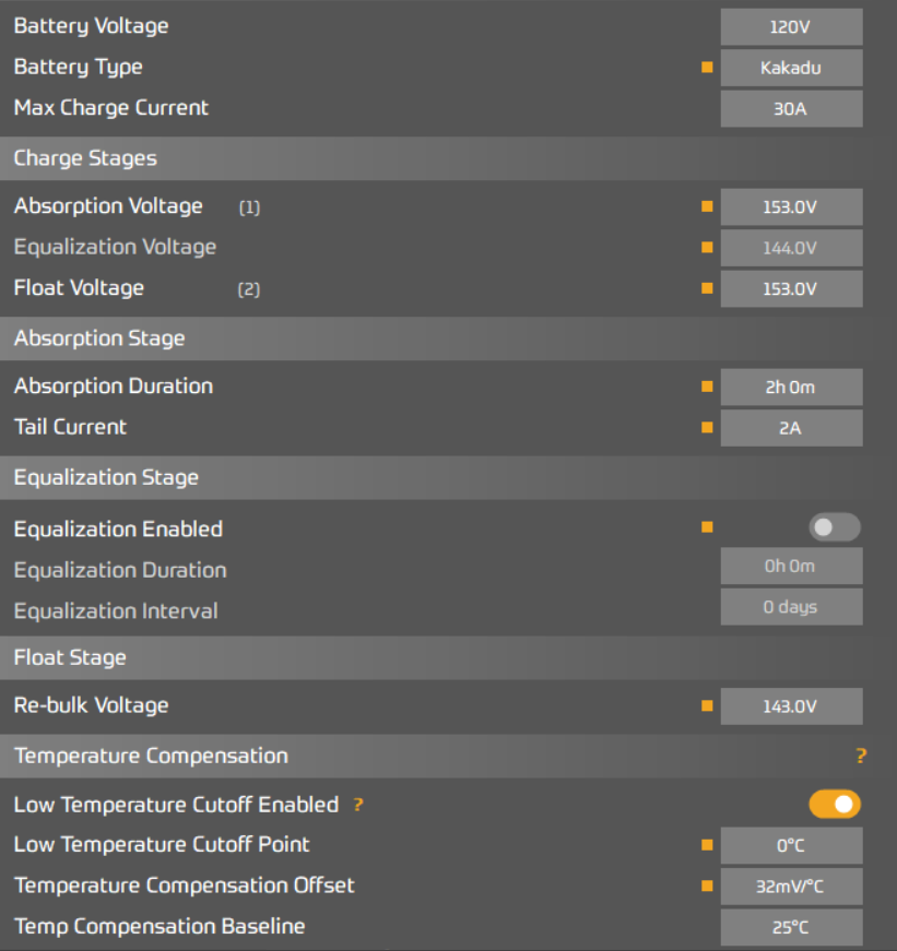
Check that the charge settings match Figure 4.1, then save the settings to the SRX.
Also set the CANBUS 120 Ω switch on every SRX to OFF (section 3.1).
Figure 4.1 AERL Link charge settings for the CoolMax SRX with the Kakadu preset and battery type.
4.3 SP PRO — System → Communication (Modbus to the Nexus)
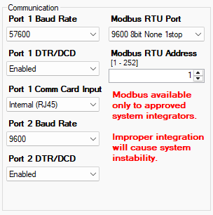
Figure 4.2 System → Communication.
Setting
Value
Port 1 Baud Rate
57600
Port 1 DTR/DCD
Enabled
Port 1 Comm Card Input
Internal (RJ45)
Port 2 Baud Rate
9600
Port 2 DTR/DCD
Enabled
Modbus RTU Port
9600 · 8 bit · None · 1 stop
Modbus RTU Address
1
These Modbus settings must match what the Nexus expects: slave 1, 9600 baud, 8N1.
AERL Kakadu · Commissioning Guide
Commissioning GuideRev 1.1.68 Nov 2026
4.4 Save, Upload and Site-Specific Settings
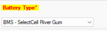
Confirm the SP LINK Battery Type is BMS – SelectCell River Gum (Figure 4.3).
Save the configuration and upload it to the SP PRO.
In SP LINK, open Data View → Battery Management and confirm that the Kakadu BMS data is shown. This view is only available with a managed battery.
Confirm in AERL Cloud that SP PRO data appears on the Nexus within about five minutes.
Figure 4.3 SP LINK Battery Type set to BMS – SelectCell River Gum.
Site-specific parameters
Installers must set up all other parameters as required for their site. These include unit application, nominal AC voltage and frequency, AC source power, generator controller settings, generator schedule start, AC input, power quality / DRM, inputs and outputs, and PowerChain settings.
4.5 Final Checks
#
Check
1
Kakadu master BMS Master Unit LED is lit, and Last Unit is lit on the final string only.
2
CAN bus runs SP PRO → Nexus → SRX … → Kakadu master BMS INV. The SP PRO connects through the SP PRO to BMS cable.
3
SP PRO CAN termination DIP switch ON. Every SRX CANBUS 120 Ω switch OFF. No termination plug at the Nexus (mid-bus).
4
RS485 runs from the Nexus to ACC Port 1 on the SP PRO (PowerChain master). The Nexus is the only Modbus master.
5
Nexus is claimed in AERL Cloud, and the Selectronic SP PRO Modbus device has been added.
6
AERL has confirmed the EMS firmware push to the Nexus and every SRX.
7
Every SRX is set up in AERL Link with the Kakadu preset and Battery Type Kakadu.
8
SP LINK: Battery Type BMS – SelectCell River Gum.
9
SP LINK Data View → Battery Management shows the Kakadu BMS data.
10
Kakadu, every SRX and the SP PRO are all reporting in AERL Cloud.
11
Site-specific parameters, including generator control, have been set.

 AERL Kakadu