 Download PDF· V1.1.1
Installation & Operation
Kakadu 120
Installation and Operating Manual
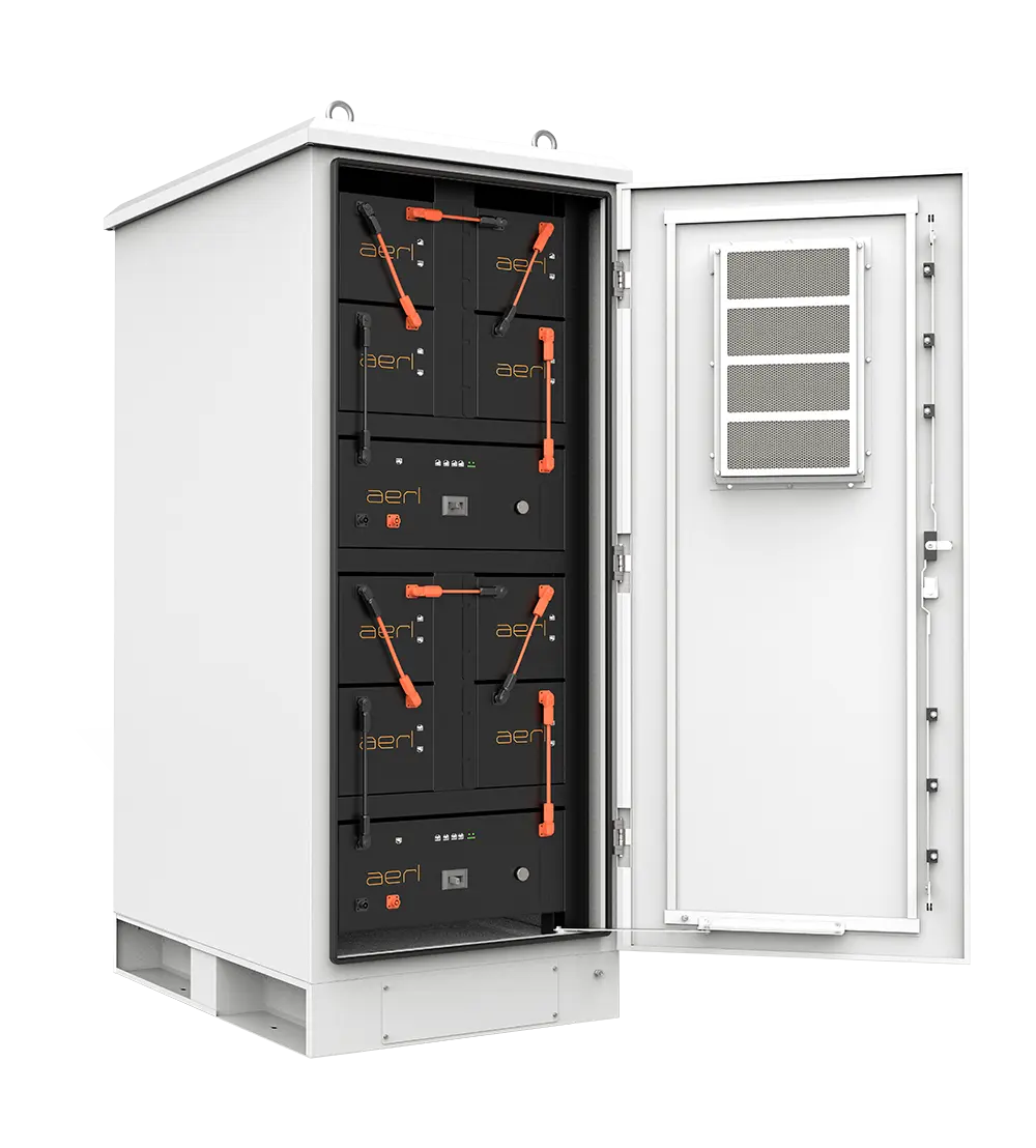
Kakadu-120-88.4
Installation & OperationV1.1.1, 8 November 2026
Download PDF· V1.1.1
Installation & Operation
Installation and Operating Manual

Installation, termination and commissioning must be carried out only by a licensed electrical worker competent in battery energy storage systems, in accordance with AS/NZS 3000 and AS/NZS 5139.
Kakadu 120 is a lithium iron phosphate battery energy storage system housed in an outdoor-rated cabinet. Each cabinet holds two independent battery strings, and up to 16 cabinets can be paralleled into a single system.
Kakadu 120 is named for its 120 V DC class battery voltage. A string consists of one BMS and four battery modules connected in series. Each module is nominally 35.2 V and 11.05 kWh, giving a string a nominal 140.8 V and 44.2 kWh. Each cabinet contains two strings, giving 88.4 kWh (nominal; usable energy at the 90% depth of discharge is 79.6 kWh). Up to 16 cabinets may be connected in parallel, for a maximum system energy of 1.41 MWh.
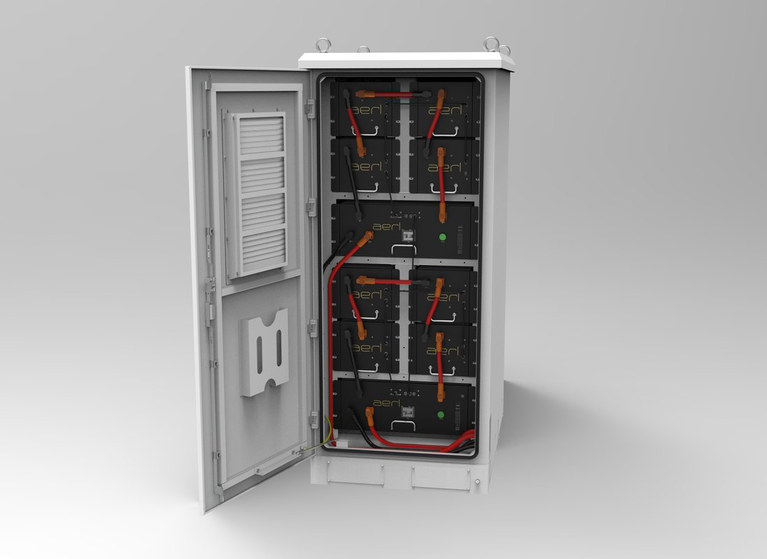
Table 2.1 — Terms used in this manual
| Term | Full name |
|---|---|
| BESS | Battery Energy Storage System |
| BMS | Battery Management System |
| BIC | Battery Information Collector |
| SOC | State of Charge |
| SOH | State of Health |
| LFP | Lithium iron phosphate (LiFePO4) |
| Module | One 35.2 V / 11.05 kWh battery module |
| String | One BMS with four modules in series (140.8 V / 44.2 kWh) |
| Cabinet | The enclosure, containing two strings (88.4 kWh) |
Installation, termination and commissioning must be carried out only by a licensed electrical worker competent in battery energy storage systems, and must follow AS/NZS 3000 and AS/NZS 5139. Power cables and plugs carry high voltage from the battery at all times, including when the system is switched off.
Follow the safety requirements in this manual strictly when installing, commissioning, operating and maintaining the product. Incorrect operation or work may damage the product and other property, or cause injury or death to the operator or to third parties.
When fixing the product with screws or other fasteners, use the correct tool and tighten to the torque given in this manual or on the product label. Read this manual before installation to ensure the product is installed and used safely.
Stop using a damaged battery immediately and dispose of it in accordance with local regulations. Damage to the battery may release electrolyte, which can cause breathing difficulties, skin irritation and chemical burns. Consult the Safety Data Sheet for more information.
If you come into contact with battery electrolyte, immediately:
A battery fire may occur if the battery is exposed to flame, an excessive heat source or extreme temperatures. A burning battery may emit carbon monoxide, carbon dioxide and other toxic gases.
If a fire occurs, dial 000 (or your local emergency number). Isolate the system if it is safe to do so, then move immediately to a safe location. Firefighters should wear full-face self-contained breathing apparatus (SCBA) and full protective gear, and use a dry chemical extinguisher to cool and extinguish the battery and prevent the fire from spreading.
Kakadu 120 ships as three separate consignments: the cabinet (with the accessories box packed inside), the BMS boxes and the battery boxes. Check all items against the list below before starting installation.
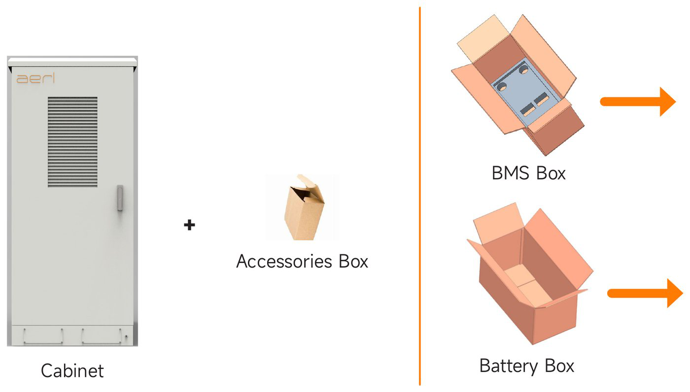
Accessories box contents
Table 4.1 — Accessories box checklist
| Item | Length | Qty |
|---|---|---|
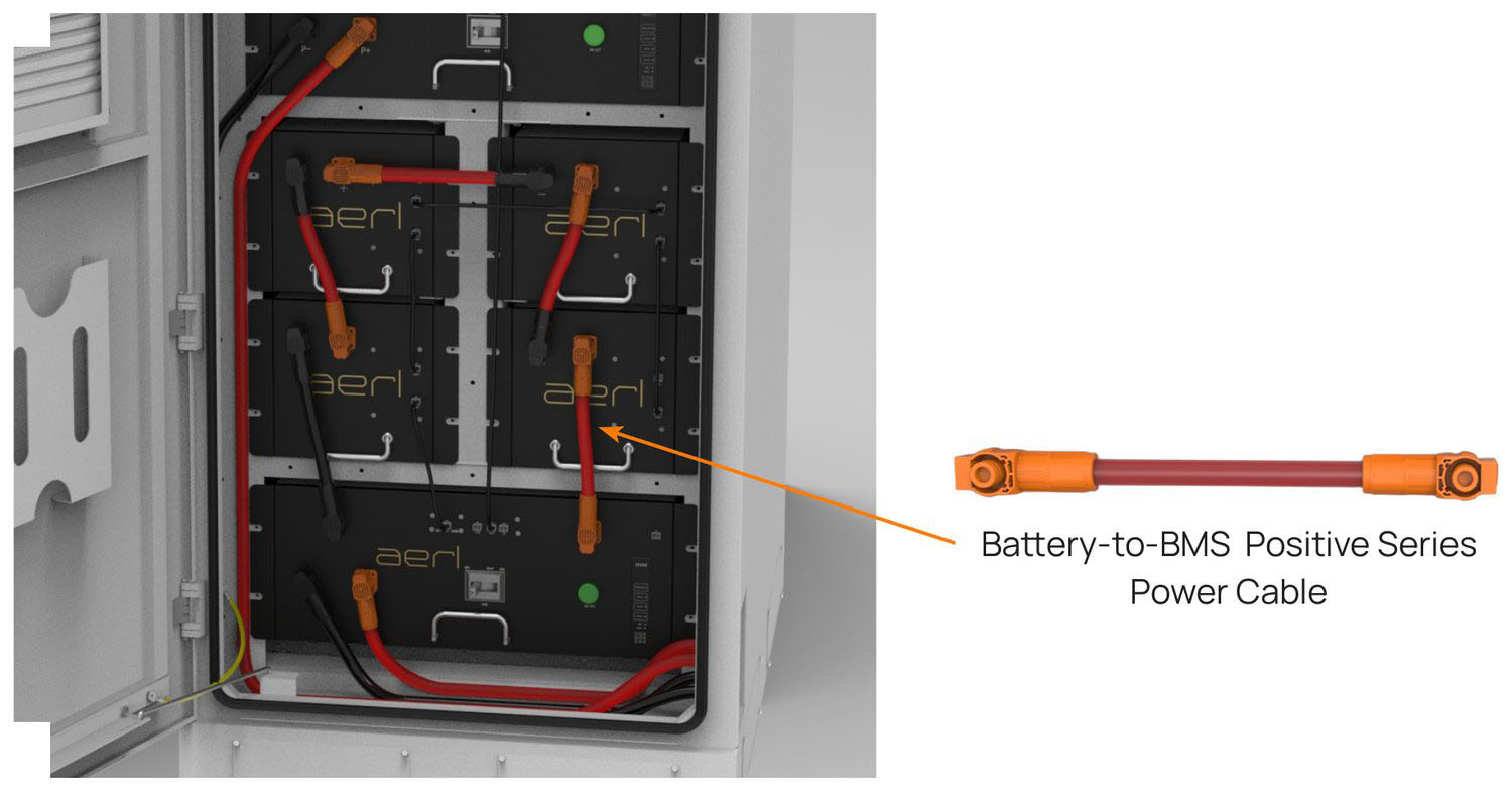
| Battery-to-BMS Positive Series Power Cable | — | 2 |
| Battery-to-BMS Negative Series Power Cable | — | 2 |
| Battery Series Power Cable A | 250 mm | 4 |
| Battery Series Power Cable B | 280 mm | 2 |
| Battery Communication Cable A | 250 mm | 4 |
| Battery Communication Cable B | 400 mm | 2 |
| BMS Communication Cable | 280 mm | 2 |
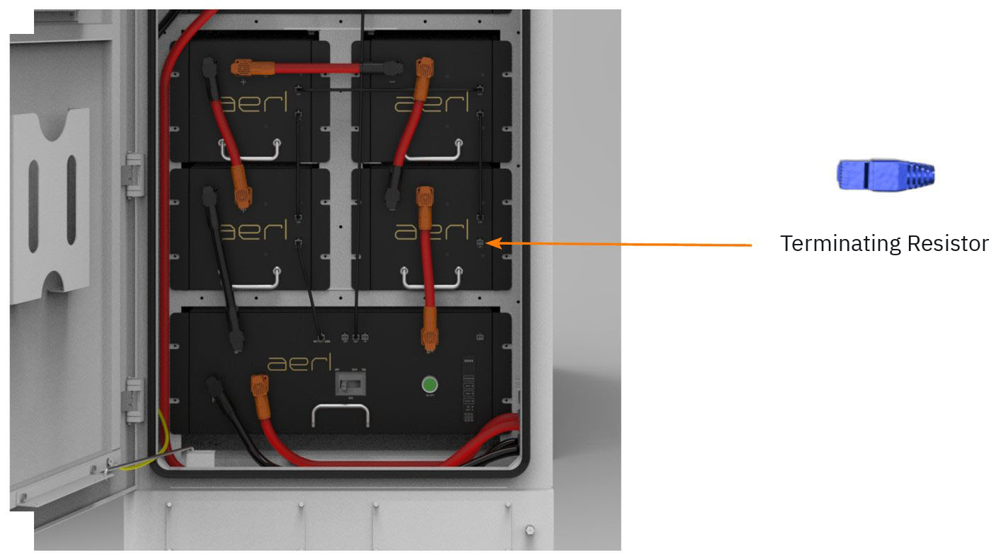
| Terminating Resistor | — | 2 |
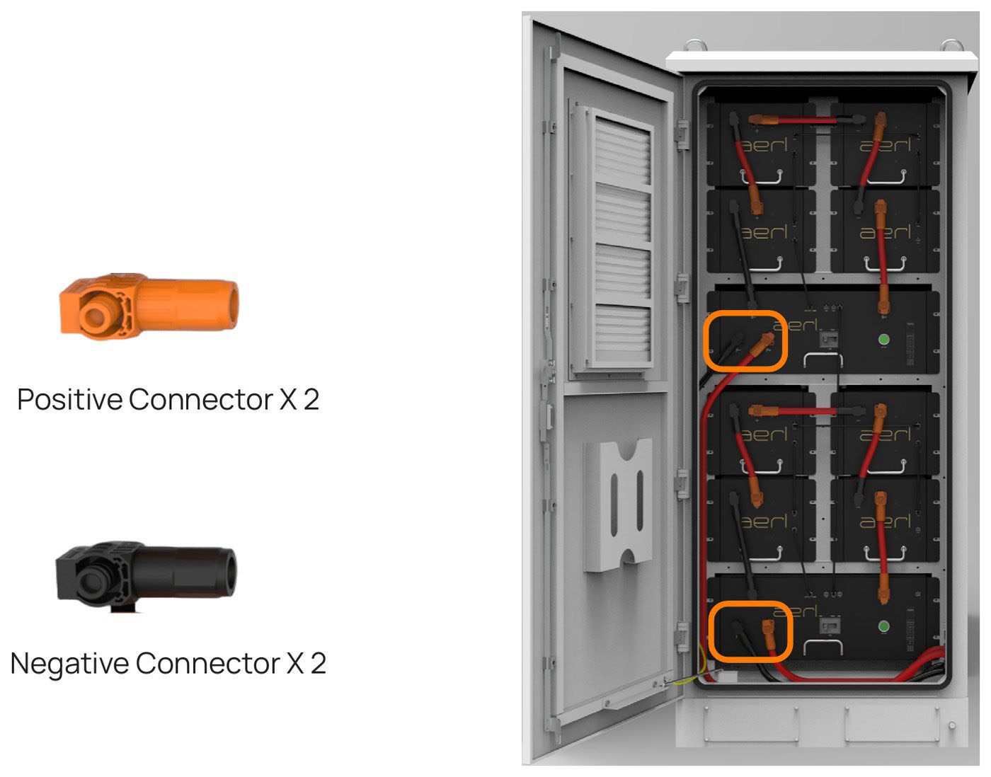
| Positive Connector | — | 2 |
| Negative Connector | — | 2 |
| Washer Bolt | — | 40 |
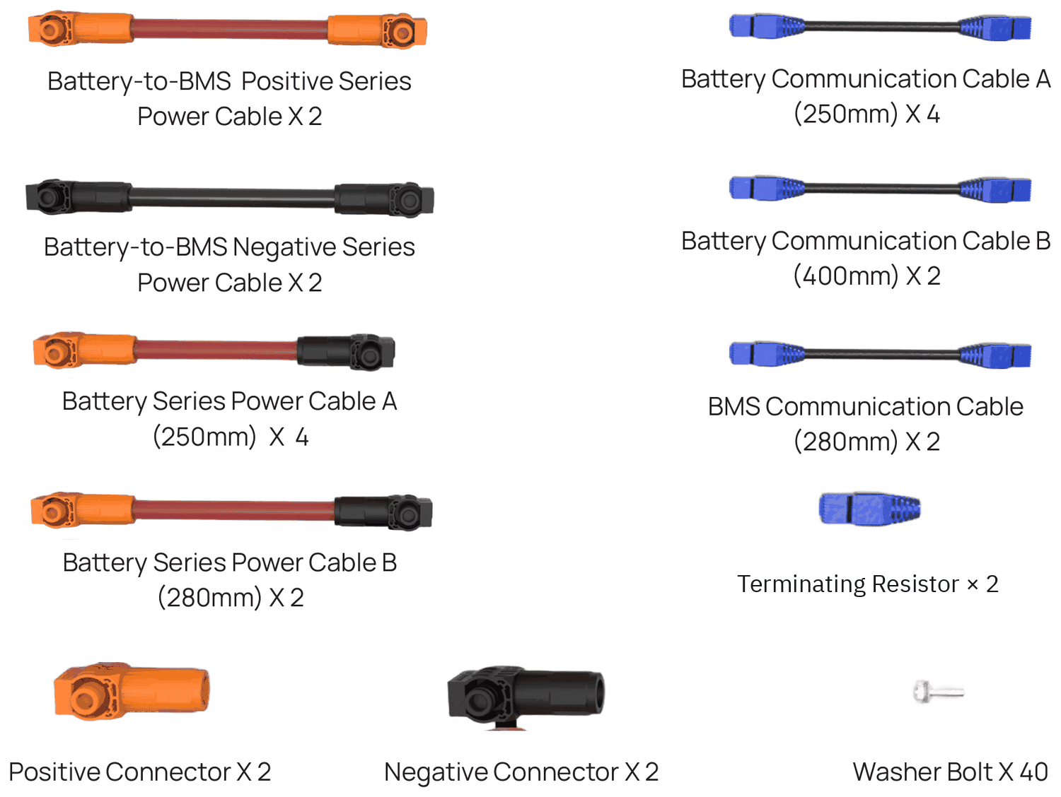

Communication cables and power cables between BMS units are not supplied. The connectors required to make them are in the accessories box — see steps 7 and 9.
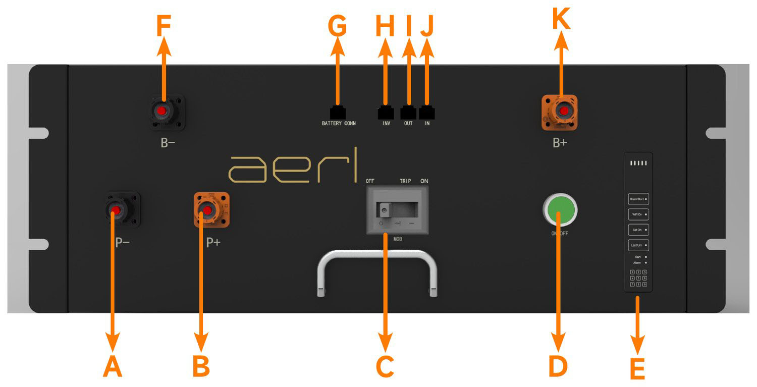
Table 4.2 — BMS front panel
| Letter | Label | Function |
|---|---|---|
| A | P– | Power terminal, negative (to inverter) |
| B | P+ | Power terminal, positive (to inverter) |
| C | MCB | Main circuit breaker |
| D | ON/OFF | System startup / shutdown |
| E | HMI | Human machine interface |
| F | B– | Power terminal, negative (to battery) |
| G | BATTERY COMM | Communication to battery |
| H | INV | Communication to the AERL Nexus Gateway (inverter CAN) |
| I | OUT | Parallel out |
| J | IN | Parallel in |
| K | B+ | Power terminal, positive (to battery) |
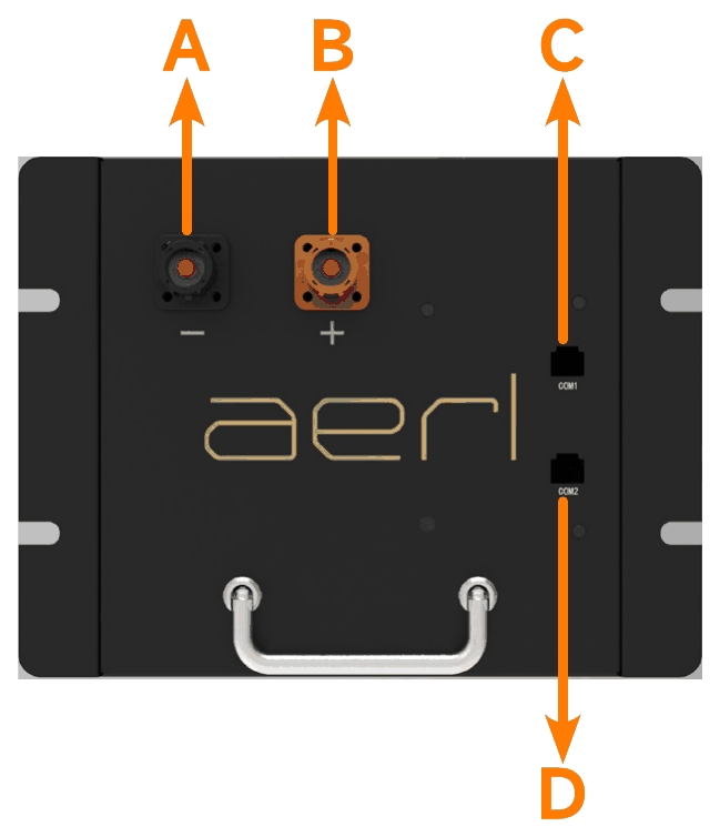
Table 4.3 — Battery module front panel
| Letter | Label | Function |
|---|---|---|
| A | – | DC negative |
| B | + | DC positive |
| C | COM1 | Communication port |
| D | COM2 | Communication port |
Table 4.4 — System specifications
| Kakadu 120 cabinet | |
|---|---|
| Part number | Kakadu-120-88.4 |
| Nominal voltage | 140.8 V DC |
| Operational voltage range | 112.2 V DC to 165 V DC |
| Capacity | 88.4 kWh / 628 Ah |
| Battery module arrangement | 2 strings / 4 modules per string |
| Depth of discharge | Up to 90% |
| Maximum continuous discharge current | 300 A @ 25 °C (150 A per string) |
| Peak discharge current (1 min) | 315 A |
| Maximum continuous charge current | 300 A @ 25 °C (150 A per string) |
| Integrated BMS circuit breaker | 2-pole, 250 A, 200 V DC |
| Lithium chemistry | LiFePO₄ / LFP |
| Cell construction | Prismatic |
| Operating temperature range | Charge −10 to 50 °C / discharge −20 to 50 °C |
| Operating humidity | Up to 95% non-condensing |
| BMS cell over-voltage protection | 3.65 V DC |
| BMS cell under-voltage protection | 2.55 V DC |
| BMS over-temperature cut-off | 56 °C |
| Prospective short-circuit current | 4500 A per string / 9000 A per cabinet |
| Altitude | < 2500 m |
| DC connectors | Quick connect for up to 50 mm² cable |
| IP rating | IP55 |
| Efficiency | > 96% |
| Cooling | Natural convection |
| Scalability | 16 cabinets in parallel |
| Series connection | Not permitted |
| Communications | CAN 2.0A |
| Weight | 970 kg |
| Dimensions (W × H × D) | 795 × 1900 × 1150 mm |
| Certifications — cell | UL 1973, UL 9540A, IEC 62619:2022, UN 38.3 |
| Warranty | 10 years — conditions apply, see chapter 11 |
Calculate the arc flash risk in accordance with AS/NZS 5139:2019 and follow its PPE requirements.
Table 4.5 — Battery module specifications
| Kakadu 35.2 battery module | |
|---|---|
| Part number | Kakadu-35.2-11S |
| Dimensions (W × H × D) | 295 × 225 × 960 mm |
| Energy | 11.05 kWh |
| Nominal voltage | 35.2 V |
| Continuous current rating | 150 A |
| Battery interconnection | Quick connector with 21 mm² (4 AWG) UL cable |
| Communications | CAN 2.0A |
| IP rating | IP20 |
| Weight | 91 kg |
| Warranty | See chapter 11 |
Kakadu 120 requires an AERL Nexus Gateway to manage the battery communications and ensure the correct charging profile is applied by the inverter.
This section gives the requirements and the step-by-step procedure for installing Kakadu 120 safely. Take the installation procedure into account when designing the system.
The installation location must be suitable for safe operation and long-term use, in accordance with AS/NZS 5139 Section 6. Choose a location where the battery can be easily connected and serviced. AERL also recommends the following.
 Safety shoes
 Insulated gloves
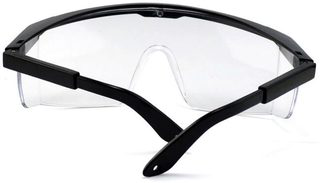 Goggles
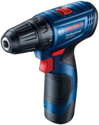 Screwdriver
 Drill
 Torque wrench
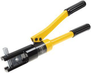 Hydraulic crimping pliers
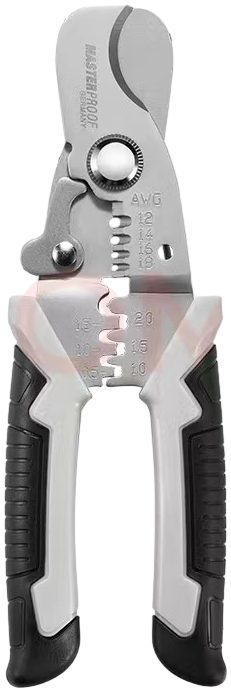 Wire cutter
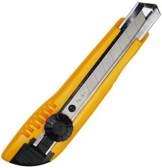 Utility knife
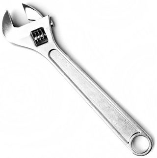 Adjustable spanner
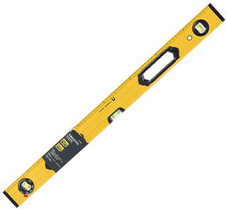 Spirit level
Installation space requirements
The figures above are the minimum clearances for the installed system. Allow additional temporary working space — approximately 750 mm — to manoeuvre the cabinet into position during installation.
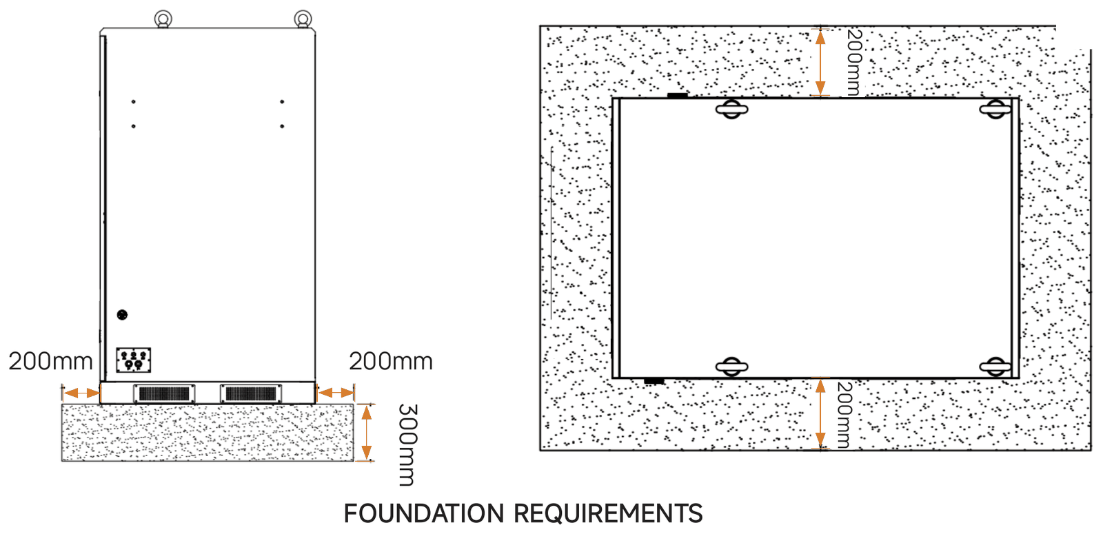
Foundation requirements
The foundation drawing is for reference only and must not be used as the final construction drawing. Verify the foundation design parameters for the energy storage system against the installation environment, ground load-bearing capacity, geological conditions and seismic requirements of the project site.
Each cabinet holds two strings. Carry out steps 1 to 8 for each string, then complete step 9.
Battery module terminals are permanently energised. Do not insert anything into the quick-connect sockets. Use only the supplied cables and connectors.
Arc flash PPE: wear PPE in accordance with AS/NZS 5139 Table 3.3.
Install the BMS, then the modules
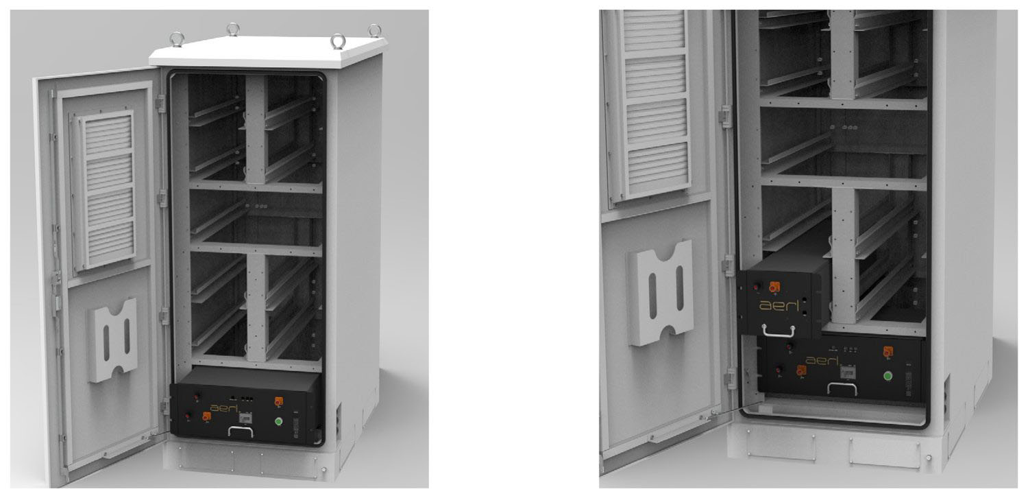
Install the BMS in the bottom position first, then install all four battery modules above it.
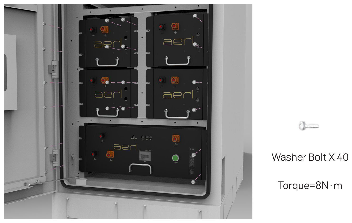
Secure every BMS and module
Lock all BMS units and battery modules in place with the washer bolts supplied. Tighten to 8 N·m.
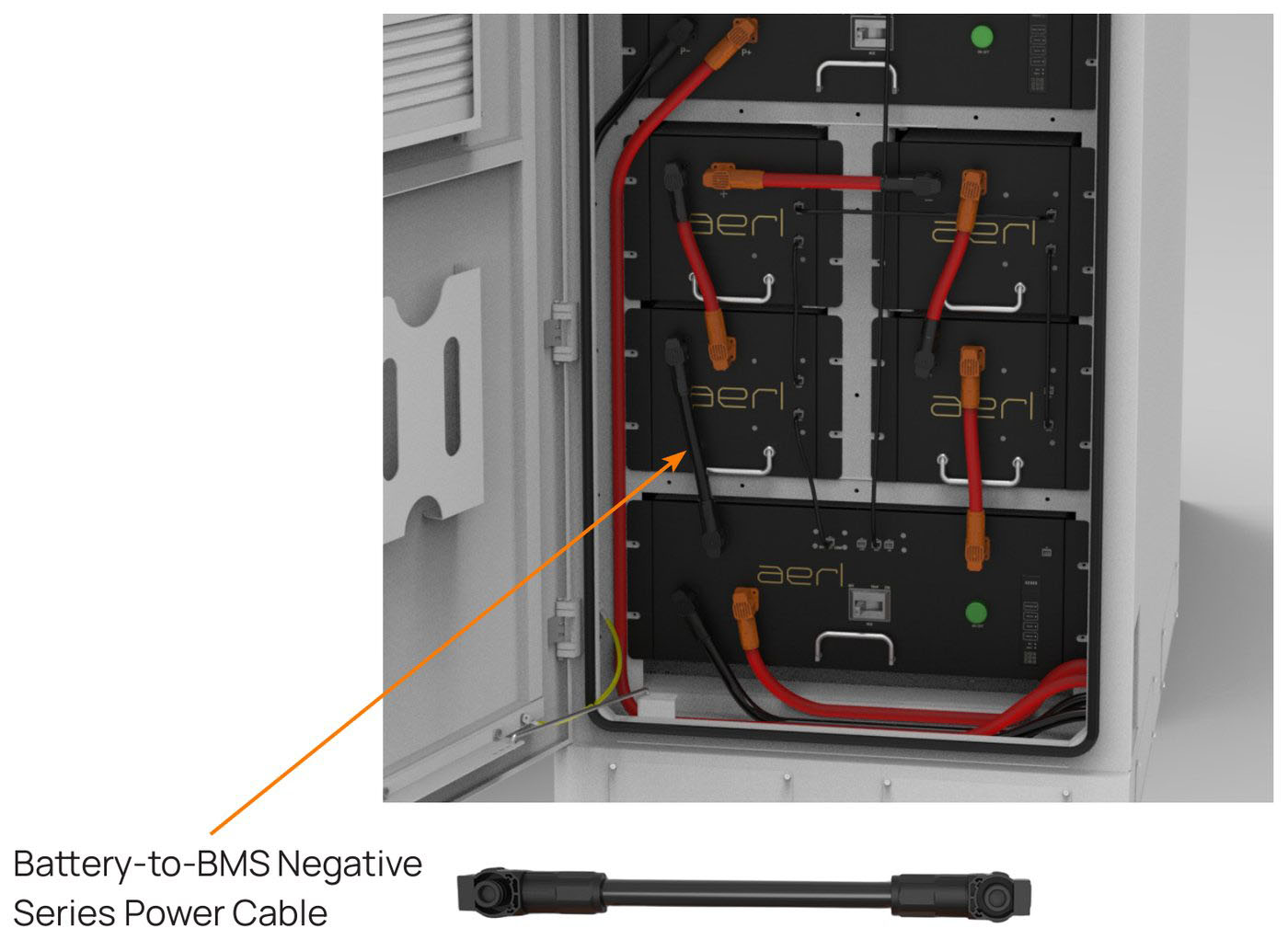
Connect the negative battery-to-BMS cable
Connect the Battery-to-BMS Negative Series Power Cable from the – port of the battery module at the bottom of the stack to B– on the BMS.
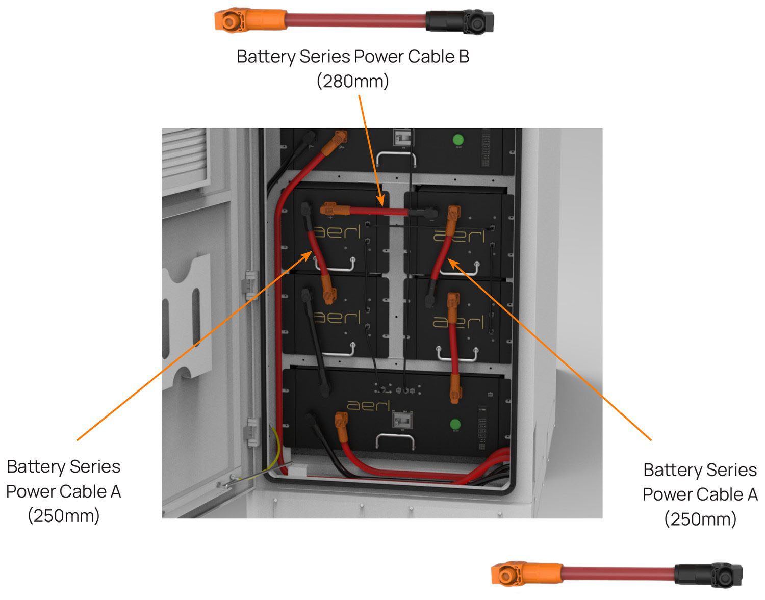
Link the modules in series
Connect Battery Series Power Cable A and Battery Series Power Cable B between the battery modules.
Always connect the black connector to a – port and the orange connector to a + port.

Battery Series Power Cable A (250 mm) and Battery Series Power Cable B (280 mm) are very similar lengths — double-check which one is which before you start. If your cable is short when connecting the left battery module to the right, you may have them the wrong way around.
Connect the positive battery-to-BMS cable
Connect the Battery-to-BMS Positive Series Power Cable from the + port of the battery module at the bottom of the stack to B+ on the BMS.
Wire the battery communication chain
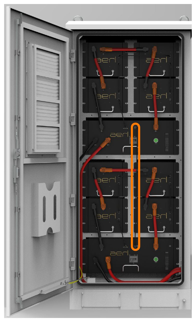
The four modules of a string sit in a 2 × 2 grid above the BMS. The communication chain runs from the BMS to the bottom-left module, up to the top-left module, across to the top-right module and down to the bottom-right module, which is the last in the chain.
Battery Communication Cable A (250 mm) and the BMS Communication Cable (280 mm) are similar lengths — make sure to identify which one is which before you start. If your cable is a little short when connecting the BMS to the bottom-left battery module, you may have them the wrong way around.
Link the BMS units
The communication cables between BMS units are not supplied. Cut and crimp them to the length required on site.
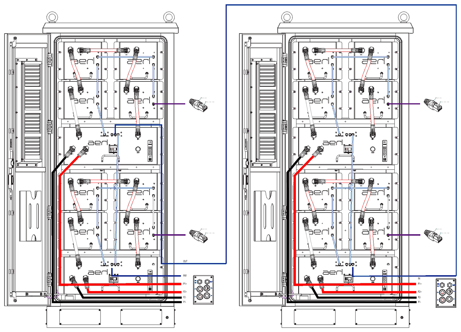
The BMS whose INV port is connected to the AERL Nexus Gateway is the master, and its Master Unit LED must be lit; on every other BMS, press Master Unit so that its LED is off (section 6.3). The other BMS units follow the master through the IN / OUT chain. With the lower BMS as the master, connect OUT on the lower BMS to IN on the upper BMS. For multiple cabinets, continue the chain as described in section 5.5.
Fit the terminating resistors
Fit a Terminating Resistor to COM2 on the last module in the communication chain — the bottom-right module — of each of the two strings in the cabinet.
Make up the BMS parallel power cables
The parallel power cables between BMS units are not supplied; use the supplied connectors. Prepare and crimp the cables to the length required on site, using the Positive Connector and Negative Connector.
Use a conductor size of up to the maximum of 50 mm² that the connectors accept. Size the cable in accordance with AS/NZS 3000.
Up to 16 cabinets may be connected in parallel. Series connection is not permitted.
The HMI presents real-time system data at a glance and provides direct control of black start and string identification.
It shows the running status and state of charge of the battery, and lets you trigger a black start, set the terminating string and identify individual strings in a paralleled system.
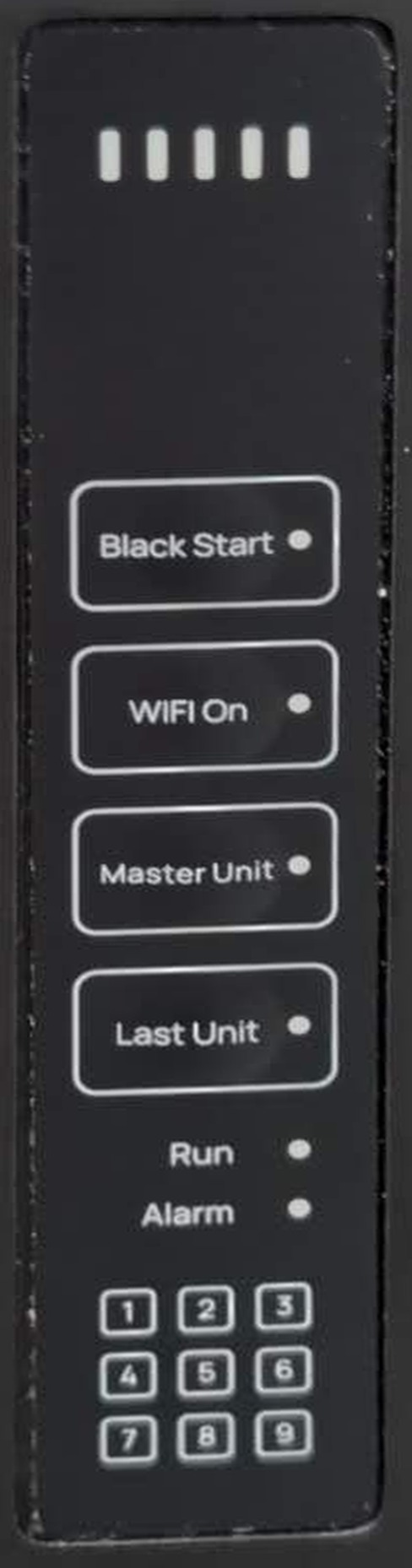 123456
The SOC indicator shows the current state of charge of the system. Each lit LED represents 20% of the battery's energy.
Table 6.1 — SOC indication
| 80% < SOC ≤ 100% | |
| 60% < SOC ≤ 80% | |
| 40% < SOC ≤ 60% | |
| 20% < SOC ≤ 40% | |
| 0% < SOC ≤ 20% |
Black start is designed for off-grid systems. It lets Kakadu 120 supply energy to the inverter so the inverter can start the system.
In an off-grid system, power up the system and then press and hold Black Start for three seconds to activate it. Once the inverter starts working, black start terminates automatically and the LED goes out.
Master Unit identifies the master BMS — the string connected directly to the Nexus Gateway — and sets the terminating resistor. It should be on for the master BMS only.
All Master Unit LEDs are on initially. Press Master Unit on each string that is not the master and confirm that its LED goes out, leaving only the master string's LED on.
Last Unit confirms which string is last in the system and completes the communication circuit.
All Last Unit LEDs are solid on by default. To complete the communication circuit, make sure that Last Unit is on for the last string only. Press the button on each of the other strings and confirm that its LED goes out.
When the system is working normally, Alarm stays off. An orange light is displayed when a serious fault occurs, such as over-voltage or over-current.
When the system is working normally, Run lights green. When the system is powered off, Run is off.
This area shows the status of every module in the string. Kakadu 120 has four battery modules per string, so indicators 1 to 4 correspond to the four modules; indicators 5 to 9 are not used and stay off.
When a module is working correctly, its indicator is off. If a module fails, its number lights orange.
Before starting the system, confirm that every cable is connected as described in this manual, and that all MCBs and DC breakers — where fitted — are off.
The RUN and SOC indicators light once the system starts working.
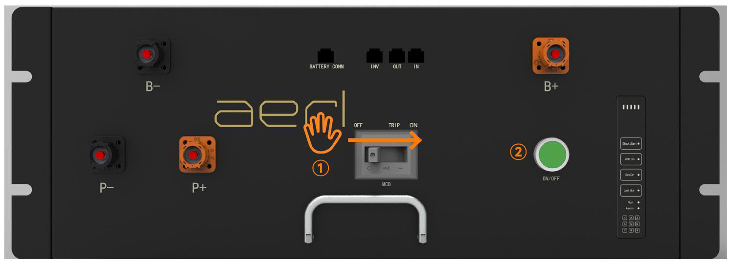
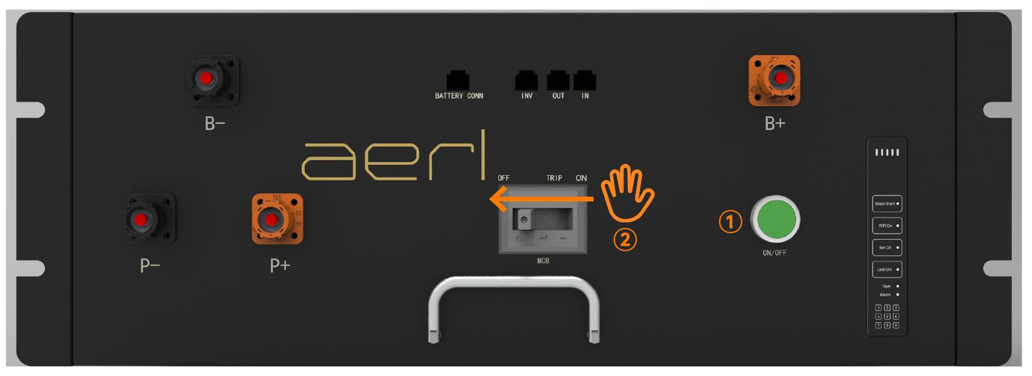
Isolate the system power supply before operating on or maintaining the battery system. Working on energised equipment may damage the battery system or cause electric shock. All work must be carried out by authorised personnel only.
Make sure the system is completely shut down before carrying out the following checks. Shutting down opens the MCB but does not de-energise the battery modules. Wear arc flash PPE in accordance with AS/NZS 5139 when working on the battery.
When disposing of Kakadu 120, return the unit to AERL, or follow local regulations for electronic waste and used batteries and observe the following requirements.
To find the product's date of manufacture, locate the serial number on the nameplate.
Kakadu 120 is covered by a 10-year warranty; conditions apply. The full terms and the claim procedure are in the Kakadu 120 Warranty Statement at aerl.com.au. For a claim, contact AERL technical support.
Australian Energy Research Laboratories
Technical support: [email protected]
Sales: [email protected]
Hours: Monday to Friday, 9:00–17:00 (AEST)