 Download PDF· Rev 1.0.0
Managed Battery Integration Guide
AERL LiFe² 5120S
Inverter Integration Over CAN Bus
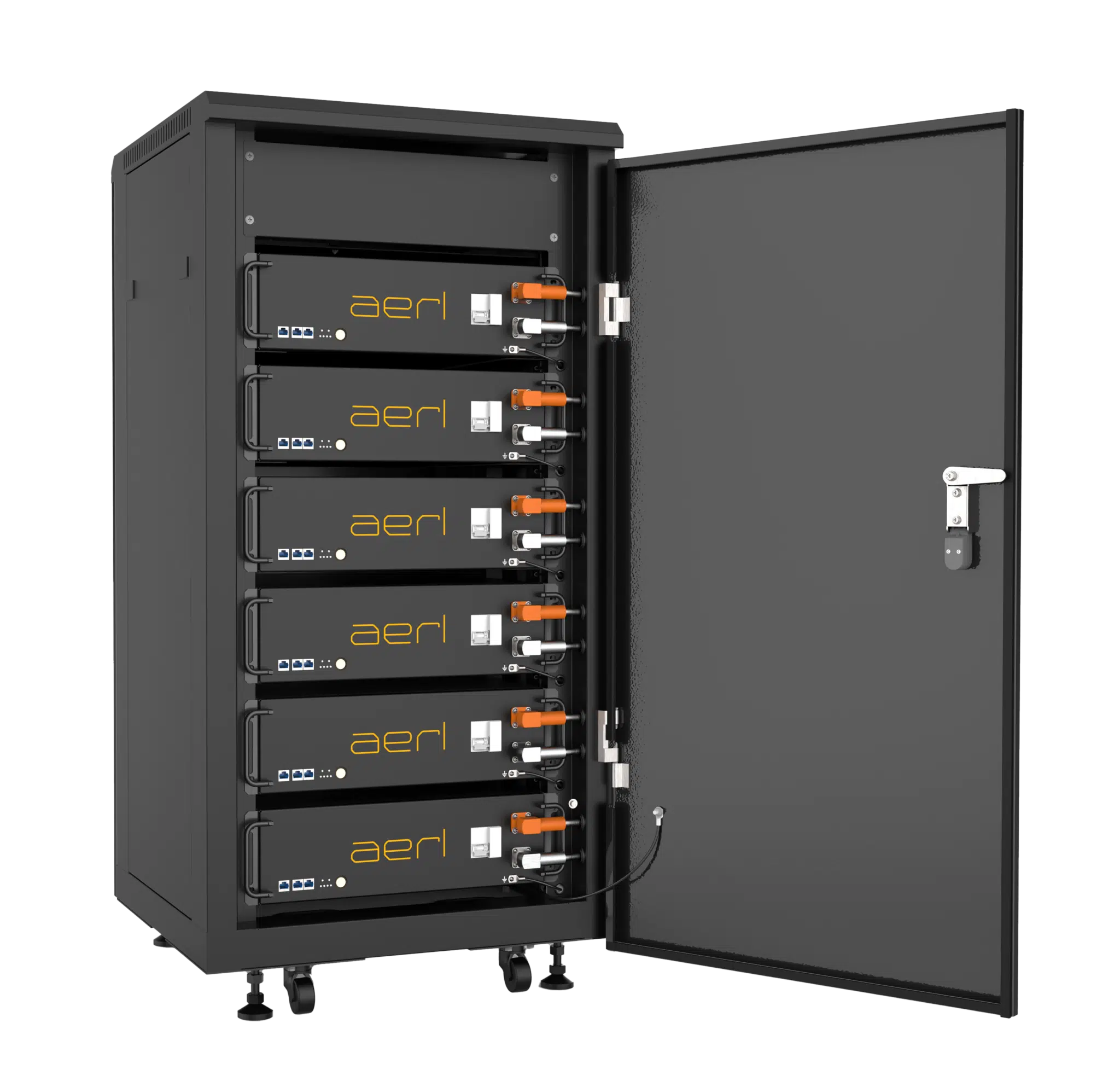
LiFe²-5120S · Managed mode
Managed Battery Integration GuideRev 1.0.0, 8 Nov 2026
Download PDF· Rev 1.0.0
Managed Battery Integration Guide
Inverter Integration Over CAN Bus
This guide covers the communication link between the LiFe² 5120S and a supported inverter in Managed mode: cabling, battery and inverter settings, and how to confirm that the link works. All other inverter configuration and the system design are the integrator's responsibility.
Before you start, read the LiFe² 5120S Installation and Operation Manual and the inverter manufacturer's installation manual. For inverters without a communication link to the battery, and for the minimum number of battery modules for inverters not listed here, use the LiFe² 5120S PCE Integration Guide.
To size a complete LiFe² system (modules, cabinets and charge sources), see the AERL LiFe² 5120S System Sizing Guide, at aerl.com.au.
Settings can change with inverter firmware. They are correct at the date of publication. Use the latest firmware the inverter manufacturer offers.
Deye, Victron Energy, Selectronic, SP PRO, SP LINK, Solis and other third-party names are trademarks of their respective owners. They are used here only to identify compatible equipment.
In Managed mode, the master battery's Battery Management System (BMS) talks to the inverter over CAN bus. The BMS sends its state of charge (SOC), its charge voltage limit, its charge and discharge current limits, and its alarms. The inverter charges and discharges within those limits and shows the battery's own SOC, so you do not program charge voltages or current limits by hand.
| Managed (comms) | Self-Managed (no comms) | |
|---|---|---|
| Link to the inverter | CAN bus from the master battery's COMM port | None |
| Charge settings | Sent by the battery | Programmed in the inverter by hand |
| SOC shown by the inverter | The battery's SOC | Calculated by the inverter |
| Status LED (master battery) | On steadily | Flashes slowly |
| Guide | This guide | LiFe² 5120S PCE Integration Guide |
The LiFe² 5120S starts in Managed mode by default. If a battery has been switched to Self-Managed mode, it returns to Managed mode automatically when the communication cable between the inverter and the master battery is connected. To switch a battery to Self-Managed mode, double-press the ON/OFF button on the master battery with the battery on: the SOC LEDs flash 3 times to confirm, and the battery remembers the mode after a restart.
The LiFe² 5120S uses CAN bus for every inverter in this guide. The battery's CAN pair is on pins 4 and 5 of its COMM port; each inverter brand has its own pins, so check the cable for your inverter.
| Inverter | Connects to | CAN_H / CAN_L at the inverter | Cable |
|---|---|---|---|
| Victron Energy (through a GX device) | GX device BMS-Can port | 7 / 8 | Victron VE.Can to CAN-bus BMS Type A cable |
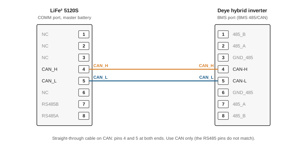
| Deye | Inverter BMS port | 4 / 5 | Straight-through |
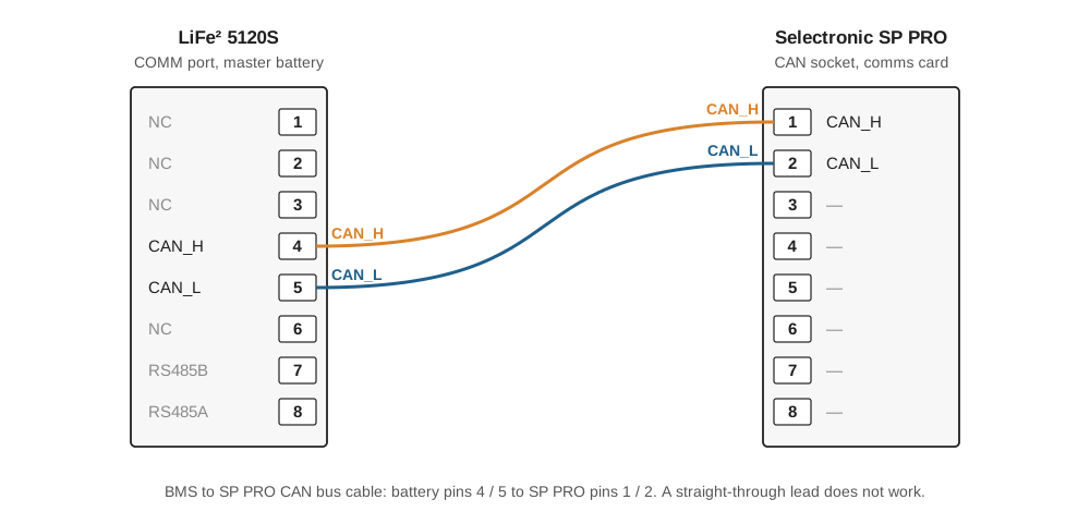
| Selectronic SP PRO | SP PRO comms card CAN socket | 1 / 2 | Selectronic BMS to SP PRO CAN bus cable |
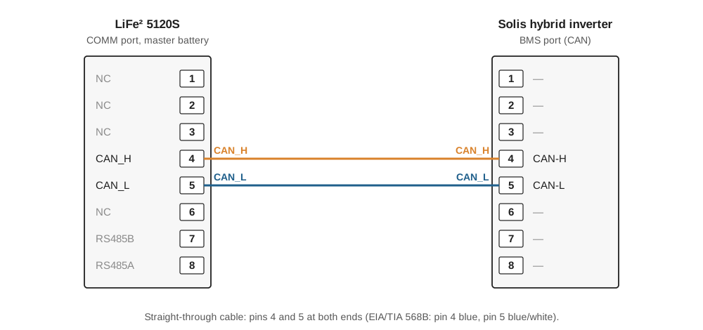
| Solis | Inverter BMS port | 4 / 5 | Straight-through |
The battery that connects to the inverter is the master battery. The LiFe² 5120S has no address or DIP switches to set: the battery whose COMM port is connected to the inverter manages the whole bank.
Up to 64 LiFe² 5120S modules can run in parallel on one chain.
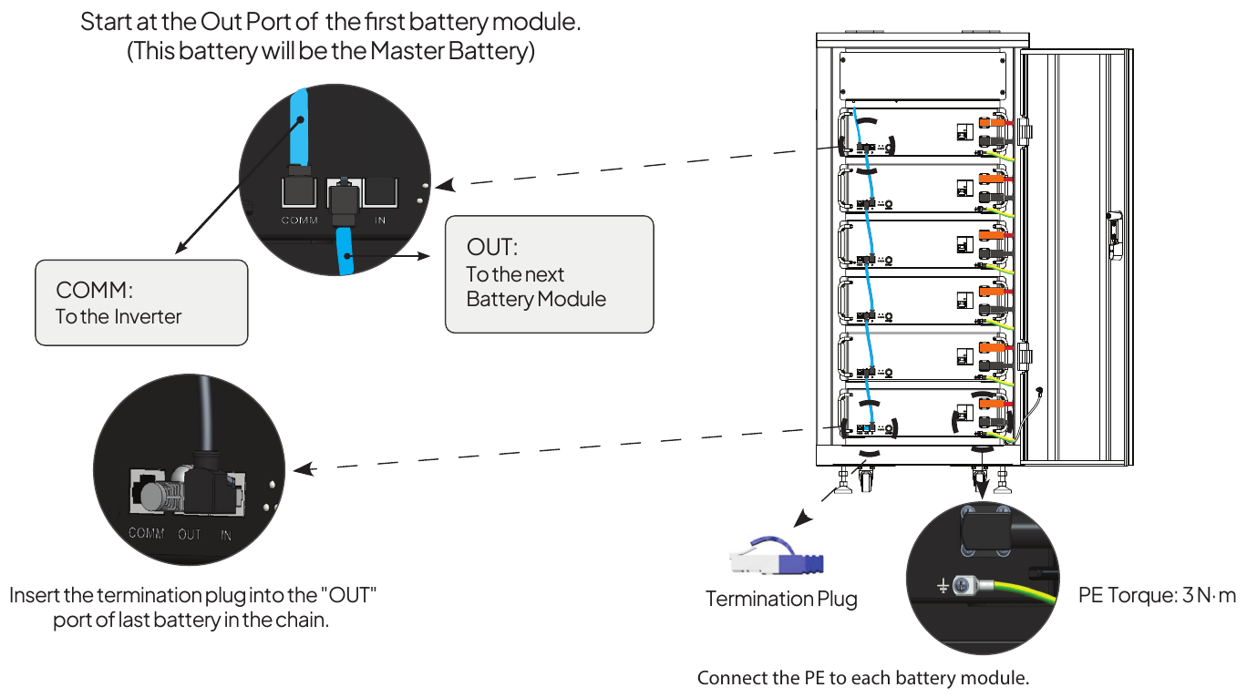
| Pin | Signal |
|---|---|
| 1 | NC |
| 2 | NC |
| 3 | NC |
| 4 | CAN_H |
| 5 | CAN_L |
| 6 | NC |
| 7 | RS485B |
| 8 | RS485A |
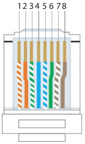
The link between the master battery and the inverter needs 120 Ω at each end:
The termination plug in the last battery's OUT port terminates the battery-to-battery chain, which is a separate bus.
For AERL Cloud monitoring, fit an AERL Nexus Gateway inline between the master battery and the inverter, with no termination plug in the Nexus (LiFe² AERL Cloud Integration Guide).
Follow the start-up sequence in the LiFe² 5120S Installation and Operation Manual (§6.3), with the comms cable already connected:
The link is working when:
Charge the system to 100% SOC when you first start it, and at least every 30 days in Managed operation, to keep the SOC accurate.
| Symptom | Check |
|---|---|
| No communication with the inverter | The comms cable is in COMM on the master battery, not IN or OUT. Only the master battery connects to the inverter. The cable is undamaged, fully seated and uses the pin mapping for your inverter. |
| Some batteries missing or not working | Each OUT connects to the next battery's IN. The termination plug is in OUT of the last battery. Try another link cable. |
| Status LED flashes slowly | The battery is in Self-Managed mode. Check the comms cable to the inverter; the battery returns to Managed mode when it is connected. |
| Error LED on | Note the battery state and contact AERL support. |
| Still not working | Restart in order: shut down the inverter; turn off the DC breaker between battery and inverter; hold ON/OFF on the master battery for 3 seconds; wait until all LEDs are off, then 3 minutes more; turn the DC breaker on; press ON/OFF for 1 second; start the inverter. |
Install the latest firmware on the GX device and the Victron products.
The minimum number of LiFe² 5120S modules for each Victron inverter/charger, per inverter, single phase or three phase, on-grid or off-grid:
| Inverter/charger | Single phase, on-grid | Single phase, off-grid | Three phase, on-grid | Three phase, off-grid |
|---|---|---|---|---|
| MultiPlus 48/500/6 | 1 | 1 | 1 | 1 |
| MultiPlus 48/800/9 | 1 | 1 | 1 | 1 |
| MultiPlus 48/1200/13 | 1 | 1 | 1 | 1 |
| MultiPlus 48/1600/20 | 1 | 1 | 1 | 2 |
| MultiPlus 48/2000/25 | 1 | 1 | 1 | 2 |
| MultiPlus 48/2000/25-50 120V | 1 | 1 | 1 | 2 |
| MultiPlus 48/3000/35 | 1 | 1 | 2 | 3 |
| MultiPlus 48/5000/70 | 1 | 2 | 2 | 4 |
| MultiPlus-II (GX) 48/3000/35-32 | 1 | 1 | 1 | 3 |
| MultiPlus-II (GX) 48/5000/70-50 | 1 | 2 | 2 | 4 |
| MultiPlus-II 120V 48/3000/35-50 | 1 | 2 | 1 | 3 |
| MultiPlus-II 120V 48/5000/70-95 | 1 | 2 | 2 | 4 |
| MultiPlus-II 48/3000/35-32 | 1 | 1 | 1 | 3 |
| Inverter/charger | Single phase, on-grid | Single phase, off-grid | Three phase, on-grid | Three phase, off-grid |
|---|---|---|---|---|
| MultiPlus-II 48/5000/70-50 | 1 | 2 | 2 | 4 |
| MultiPlus-II 48/8000/110-100 | 1 | 3 | 3 | 7 |
| MultiPlus-II 48/10000/140-100 | 2 | 3 | 3 | 8 |
| MultiPlus-II 48/15000/200-100 | 2 | 4 | 4 | 12 |
| Quattro 48/3000/35-50/50 120V | 1 | 1 | 2 | 3 |
| Quattro 48/5000/70-100/100 120V | 1 | 2 | 2 | 4 |
| Quattro 48/10000/140-100/100 120V | 2 | 3 | 3 | 8 |
| Quattro 48/5000/70-100/100 | 1 | 2 | 2 | 4 |
| Quattro 48/8000/110-100/100 | 1 | 3 | 2 | 7 |
| Quattro 48/10000/140-100/100 | 2 | 3 | 4 | 8 |
| Quattro 48/15000/200-100/100 | 2 | 4 | 4 | 12 |
| Quattro 48/15000/200-100/100 277V | 2 | 4 | 4 | 12 |
| Quattro-II 48/5000/70-50 | 1 | 2 | 2 | 4 |
| RS Smart Solar 48/6000 | 1 | 2 | 2 | 4 |
| Multi RS Solar 48/6000 | 1 | 2 | 2 | 4 |
| Multi RS Solar 48/6000 Dual Tracker | 1 | 2 | 2 | 4 |
| EasySolar-II 48/3000/35-32 MPPT 250/70 GX | 1 | 1 | 2 | 3 |
| EasySolar-II 48/5000/70-50 MPPT 250/100 GX | 1 | 2 | 2 | 4 |
Use the Victron VE.Can to CAN-bus BMS Type A cable (ASS030710118). Plug the end labelled CAN-bus BMS into COMM on the master battery and the end labelled VE.Can into the GX device's BMS-Can port.
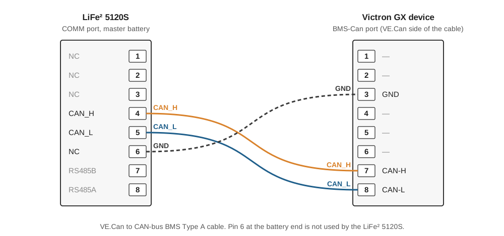
Terminate the GX device end with a VE.Can terminator (supplied with the GX device). The battery end is terminated inside the master battery. Do not put the battery on the same CAN bus as VE.Can devices.
| Setting (Remote Console) | Value |
|---|---|
| Settings → Connectivity → port the battery is on → CAN-bus profile | CAN-bus BMS LV (500 kbit/s) (a BMS-Can port runs at 500 kbit/s) |
| Settings → System Setup → Charge Control → DVCC | Leave as the GX device sets it. With a compatible CAN-bus battery connected, the GX device sets DVCC and locks it. |
| Settings → System Setup → Batteries → Battery monitor | Automatic, or select the LiFe² battery, so that the GX device shows the battery's own SOC |
| ESS (grid-connected systems) | Set in the GX device's ESS settings to suit the site |
The battery's charge voltage and current limits replace the charge settings in VEConfigure and VictronConnect: the Multis, Quattros, RS models and solar chargers charge to the limits the battery sends, so charge voltages set there have no effect.
| Symptom | Check |
|---|---|
| Battery not in the Device List | The cable is a Type A cable, CAN-bus BMS end at the battery. It is in the BMS-Can port (or a VE.Can port set to CAN-bus BMS LV (500 kbit/s)), not a VE.Bus port. The terminator is fitted at the GX device. |
| Wrong protocol or speed | Set the CAN-bus profile to CAN-bus BMS LV (500 kbit/s). A port left at VE.Can (250 kbit/s) cannot read the battery. |
| "BMS connection lost" alarm, inverter shuts down | The inverter/charger stopped receiving the battery's limits. A low battery voltage alarm may appear at the same time: it is caused by the lost communication, not low voltage. Restore the connection, then restart the inverter/charger (GX device: the VE.Bus device's Advanced menu). |
| Solar chargers not following the battery | Each solar charger connects to the GX device (VE.Direct or VE.Can). On a VE.Can bus they need their own CAN port, separate from the battery. |
Deye's approved battery list covers this battery on CAN, with Lithium Mode 00, for these low-voltage hybrid inverters:
| Single phase | Three phase |
|---|---|
| SUN-(3.6–8)K-SG05LP1-EU and -AU | SUN-(5–12)K-SG04LP3-EU |
| SUN-(3–6)K-SG03LP1-EU | SUN-(5–12)K-SG04LP3-AU |
| SUN-(3–6)K-SG04LP1-EU and -AU | |
| SUN-(7.6–8)K-SG01LP1-EU, SUN-(12–16)K-SG01LP1-EU | |
| SUN-(5–8)K-SG01LP1-US |
Connect the inverter's BMS port (labelled BMS 485/CAN on single-phase models, BMS on three-phase models) to COMM on the master battery. Both ends carry CAN on pins 4 and 5, so a straight-through shielded Cat 5 cable works. Use CAN only: the RS485 pins on the two ports do not match.
On the inverter display, open System Setup → Battery Setting.
| Page | Setting | Value |
|---|---|---|
| Batt Mode | Batt Mode | Lithium |
| Batt Mode | Batt Capacity | Total Ah of the LiFe² 5120S modules installed (100 Ah per module) |
| Batt Mode | Max A Charge, Max A Discharge | To suit the system. The inverter also stays within the limits the battery sends. |
| Batt Set3 | Lithium Mode | 00 |
| Batt Set3 | Shutdown | 20% (default; adjust to suit the site) |
| Batt Set3 | Low Batt, Restart | Above the Shutdown level, to suit the site |
Under System Setup → Advanced Function, BMS_Err_Stop sets what happens if communication with the battery is lost: when it is active, the inverter stops and reports a fault.
| Symptom | Check |
|---|---|
| comm./FXX on the main screen; Li-BMS page empty | The cable is in the inverter's BMS port and in COMM on the master battery. Lithium Mode is 00. Batt Mode is Lithium. |
| Fault F58 (BMS communication fault) | Communication with the battery was lost while BMS_Err_Stop is active. Check the cable, then restart the system in order. |
| Wrong protocol | Lithium Mode must be 00 for this battery. Other numbers are other batteries' protocols. |
| Communication drops when the cable is moved | Replace the cable; check pins 4 and 5 for continuity end to end. |
The SP PRO carries CAN on pins 1 and 2 of its comms card CAN socket; the battery uses pins 4 and 5. Use Selectronic's BMS to SP PRO CAN bus cable, which re-maps the pins and works either way round. A standard straight-through patch lead does not work.
The SP PRO is one end of the CAN bus: set the CAN termination DIP switch on its comms card to ON. The master battery terminates the other end internally.
| Symptom | Check |
|---|---|
| SP PRO beeping; CAN bus Comms LED on steadily | No CAN communication. Check the cable is the BMS to SP PRO CAN bus cable (pins 1 / 2 at the SP PRO, 4 / 5 at the battery), not a straight-through lead, and that it is in COMM on the master battery. |
| Battery Management values blank or invalid | The managed battery type is selected and saved to the SP PRO (steps 4–5). The SP PRO firmware is 16.11 or later and the comms card firmware 5.31 or later. Restart the battery DC supply (step 6). |
| Some Module Status readings greyed out | Normal: they do not apply to this battery type. |
| Multi-phase system not reading the battery | The CAN cable goes to the L1 SP PRO only. |
| Intermittent communication | The comms card CAN termination DIP switch is ON. |
This chapter covers the Solis low-voltage (48 V) hybrid and off-grid inverters with a CAN BMS port:
The Solis BMS port carries CAN on pins 4 (CAN-H, blue) and 5 (CAN-L, blue/white), as the battery does, so a straight-through shielded Cat 5 cable works. Check the pin sequence of any made-up cable before you connect it.
S6-EH1P-L models (SolisCloud app): open More Tools → Local Operation → Connect with Bluetooth, log in as Installer, then go to Setting → Battery Setting.
| Setting | Value |
|---|---|
| Battery Type | Lithium Battery |
| Battery Model | Lithium Battery LV (at the bottom of the list). Do not select Lithium Battery LV(RS485). |
| Over-discharge SOC | 20% (default; adjust to suit the site) |
| Force-charge SOC | 10% (Solis default; keep it below the Over-discharge SOC) |
S6-EO1P(4–5)K-48: Advanced Settings (password 0010) → 3. Battery Settings → Battery Select: Lithium battery (the communicating option; the "without comm" options are for Self-Managed batteries). Set Overdischar SOC to 20% and Force SOC Set to 10% (defaults; adjust to suit the site).
S5-EH1P-L: Advanced Settings (password 0010) → Storage Energy Set → Battery Select: Lithium Battery LV. Set OverDischg SOC to 20% and ForceCharge SOC to 10% (defaults; adjust to suit the site).
After setup, check that the inverter's battery status shows the battery communicating:
| Alarm | Check |
|---|---|
| CAN Fail | CAN communication with the battery is lost. Check the cable (pins 4 and 5 at both ends) and that it is in COMM on the master battery. Check that the Battery Model is Lithium Battery LV, not the RS485 variant. |
| BatName-FAIL | Wrong battery selection. Check Battery Setting → Battery Model (or Battery Select). |
| NO-Battery | The battery is not connected, or it is off. Check the DC breakers and that the battery is on. |
The LiFe² 5120S warranty is 5 years. Register the battery within 60 days of installation to extend it to 10 years: register at aerl.com.au/warranty-registration. Conditions apply: see the LiFe² Warranty Statement, at aerl.com.au.
Before you contact AERL, note the inverter model and firmware, the number of LiFe² 5120S modules, and what the inverter and the battery LEDs show. Contact AERL support on 1800 950 865 or [email protected].
| Revision | Date | Change |
|---|---|---|
| 1.0.0 | 11 / 2026 | First issue. |
If you have any questions or need support, contact AERL.
Sincerely,
The AERL Team
AERL Pty Ltd · 1/75 Bluestone Circuit, Seventeen Mile Rocks QLD 4073 · 1800 950 865 · [email protected] · aerl.com.au
Australian Energy Research Laboratories
1/75 Bluestone Circuit
Seventeen Mile Rocks QLD 4073
Australia