 Download PDF· Rev 2.0.1
Quick Start Guide
AERL LiFe²
Batteries and Battery Cabinets
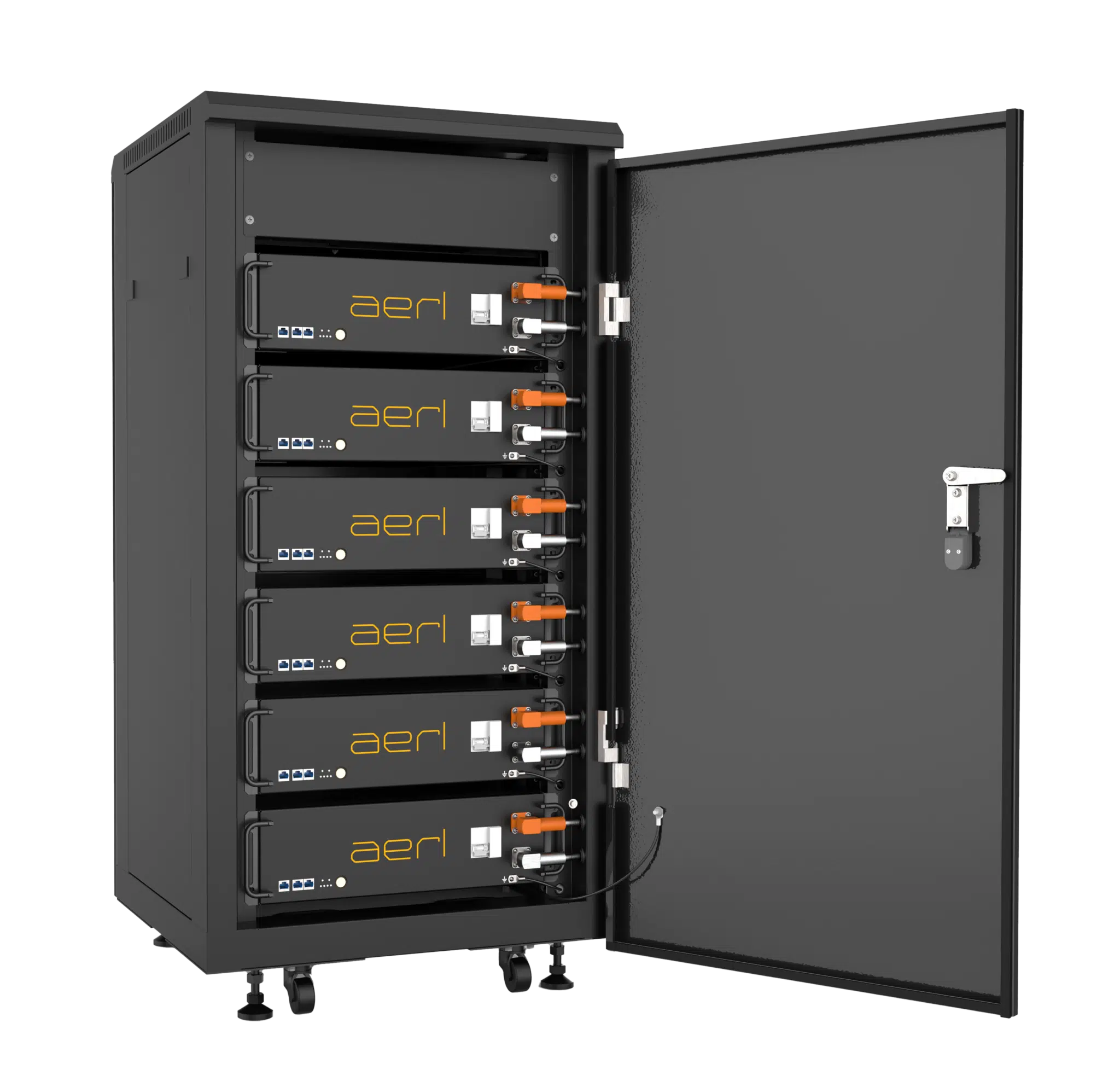
LiFe²-5120S · LiFe²-CAB6 · LiFe²-CAB10
Quick Start GuideRev 2.0.1, 8 Nov 2026
Download PDF· Rev 2.0.1
Quick Start Guide
Batteries and Battery Cabinets
Follow the safety requirements in the LiFe² 5120S Installation and Operation Manual when installing, commissioning, operating and maintaining the product. Not following them can damage the product and other property, or cause injury or death. Tighten screws and fasteners to the torque given in the manual, with the correct tools. Read the manual in full before installation.

| # | Part | Qty |
|---|---|---|
| 1 | Termination Plug | 1 |
| 2 | Comms Cable | 1 |
| 3 | M6 × 16 Bolt | 4 |
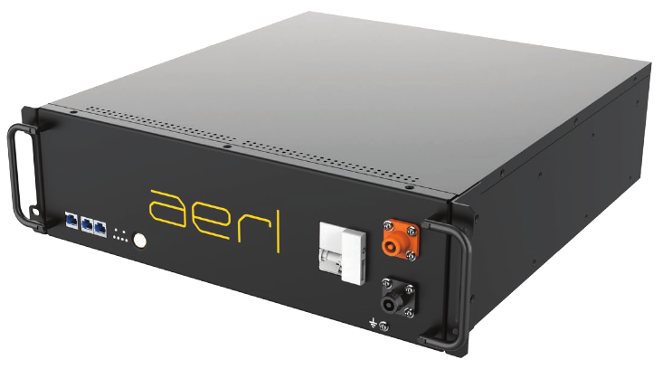

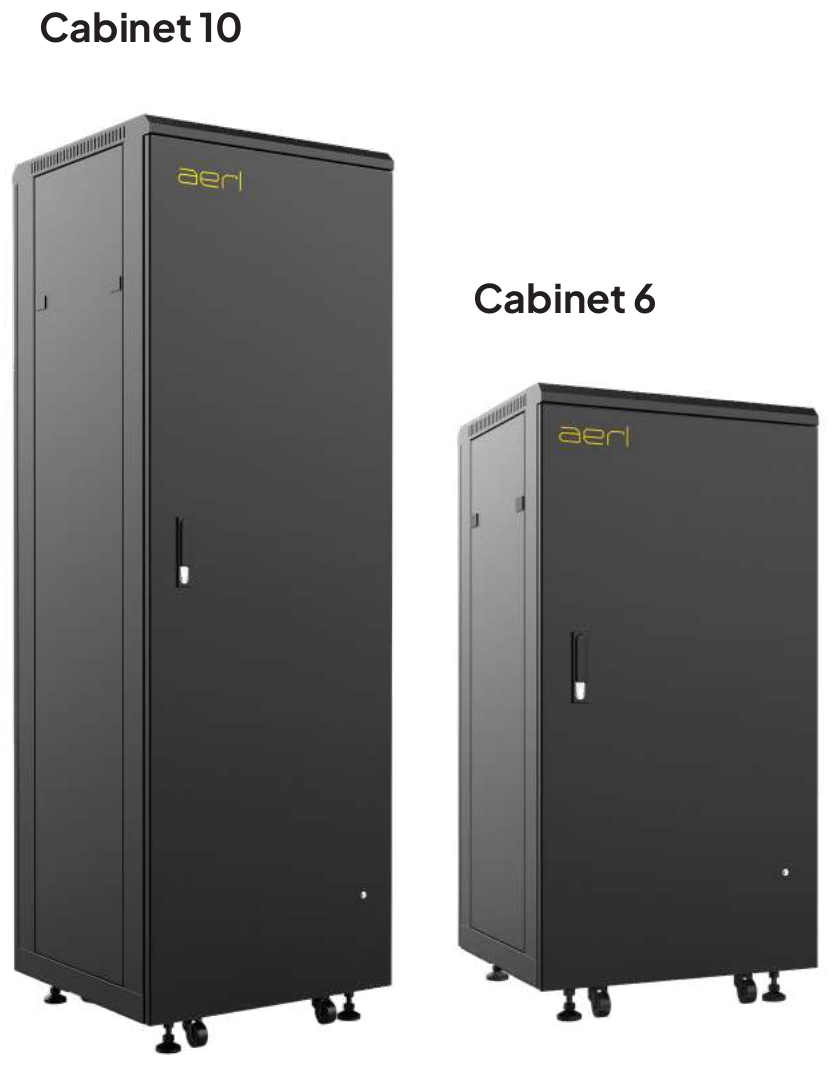
| Specification | LiFe²-CAB6 | LiFe²-CAB10 |
|---|---|---|
| Dimensions (W × H × D) | 620 × 1270 × 600 mm | 620 × 1890 × 600 mm |
| Max. Qty of Modules | 6 (30.72 kWh) | 10 (51.20 kWh) |
| Max. Continuous Current | 625 A | 1250 A |
| IP Rating | IP20 | IP20 |
| Weight | 91 kg | 128 kg |
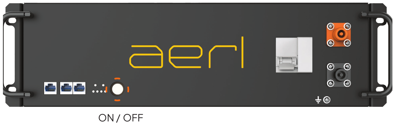
The front-panel LEDs show the battery state (Status, Error and SOC).
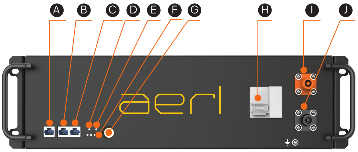
| Letter | Label | Function |
|---|---|---|
| A | COMM | Inverter Comms |
| B | OUT | Battery Comms Out |
| C | IN | Battery Comms In |
| D | N/A | Error Indication |
| E | N/A | Battery Status |
| F | N/A | SOC Indicator |
| G | ON/OFF | On/Off Switch |
| H | MCB | Circuit Breaker |
| I | + | DC+ Port |
| J | − | DC− Port |
| LED | Status | Description |
|---|---|---|
| Error | Red ON | An error has occurred. |
| Error | Off | There are no active errors. |
| Status | Green ON | The battery is active and can be charged and discharged. |
| Status | Off | The battery is not active. |
| SOC | 4 LEDs ON | 75–100% SOC |
| SOC | 3 LEDs ON | 50–75% SOC |
| SOC | 2 LEDs ON | 25–50% SOC |
| SOC | 1 LED ON | 0–25% SOC |
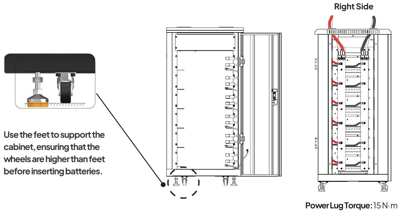
Power Lug Torque: 15 N·m
Lower the support feet until the wheels are off the floor before you insert any batteries.
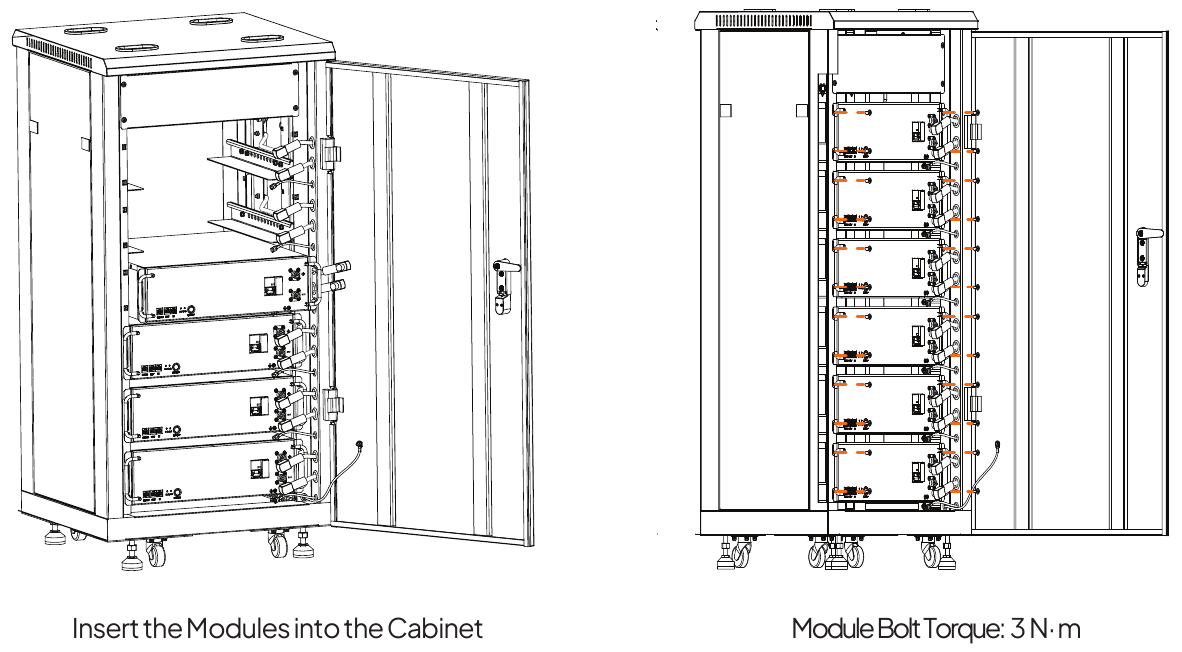
Slide the modules into the cabinet from the bottom up, and fasten each one.
Module Bolt Torque: 3 N·m
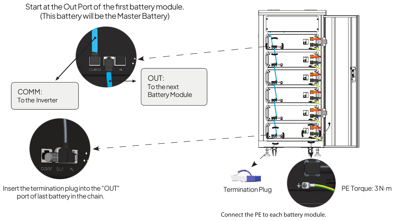
Insert the termination plug into the OUT port of the last battery in the chain.
Connect the PE to each battery module.
PE Torque: 3 N·m
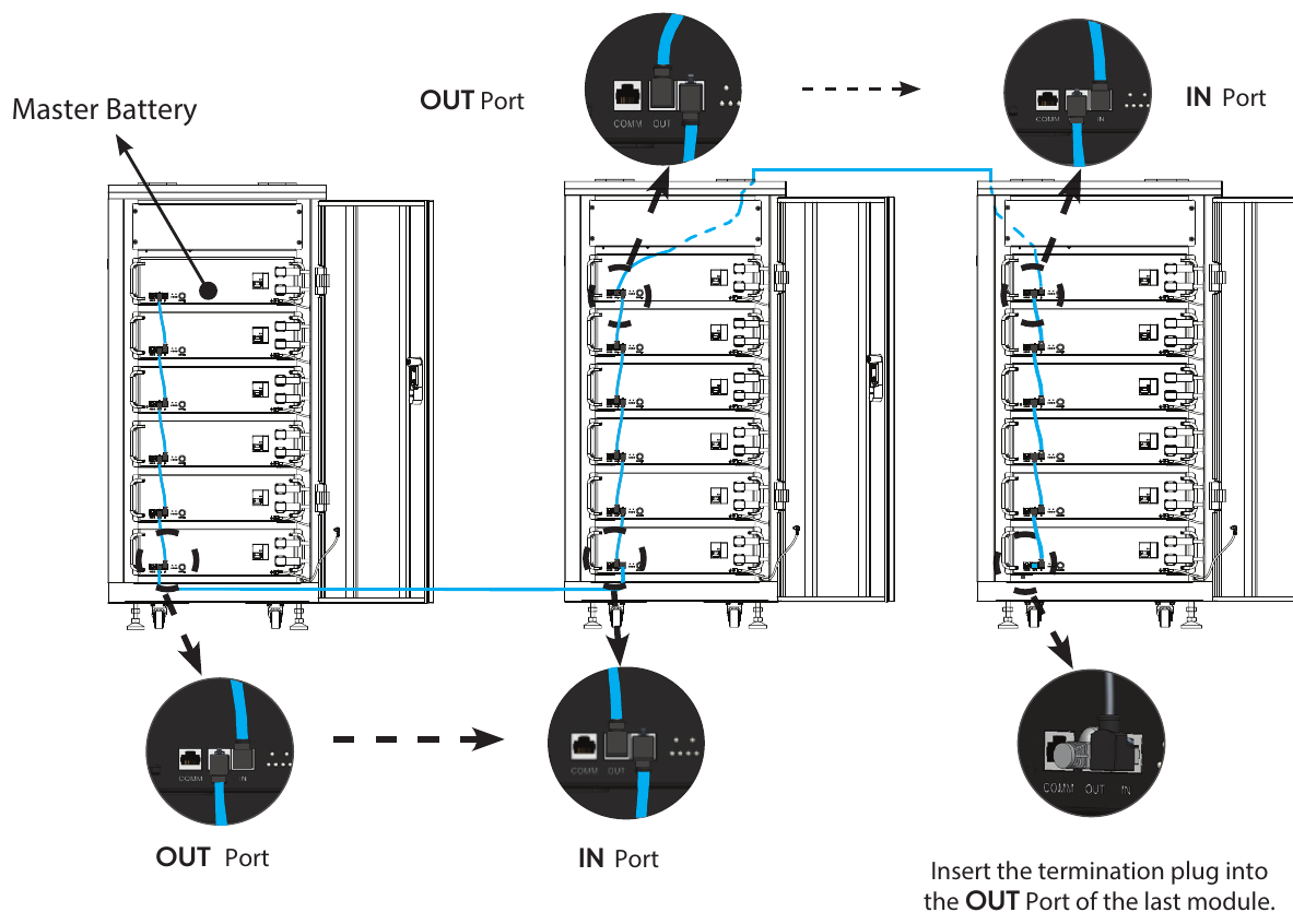
Insert the termination plug into the OUT port of the last module.
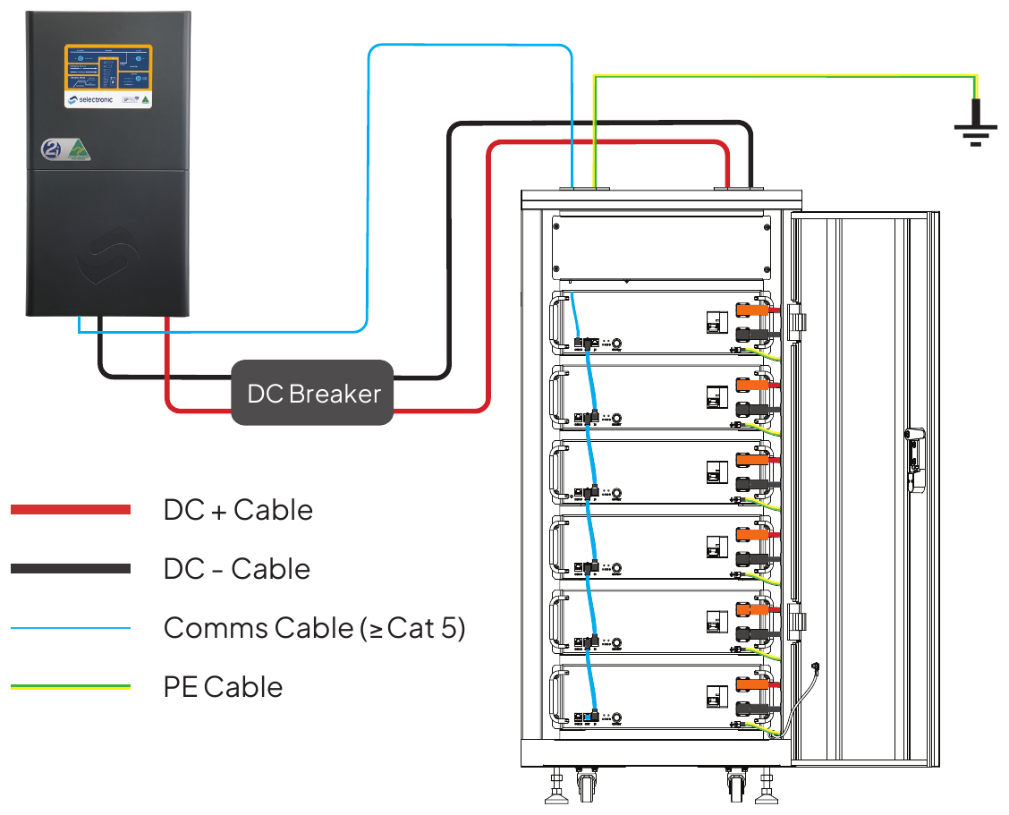
Connect the DC power cables and the comms cable between the master battery and the inverter.

The comms cable must be Cat 5 or higher.
Cable legend:
The LiFe² 5120S starts in Managed (communication) mode by default.
Use Self-Managed mode when the inverter has no communication link to the battery (a no-comms or Self-Managed PCE). To switch to Self-Managed (No Comms) mode: with the battery on, double-press the ON/OFF button on the master battery. The SOC LEDs flash 3 times to confirm. The battery remembers the mode after a restart, so you set it once.
The battery switches back to Managed mode automatically when the communication cable between the inverter and the master battery is connected.
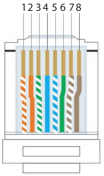
| PIN No. | 1 | 2 | 3 | 4 | 5 | 6 | 7 | 8 |
|---|---|---|---|---|---|---|---|---|
| Definition | NC | NC | NC | CAN_H | CAN_L | NC | RS485B | RS485A |
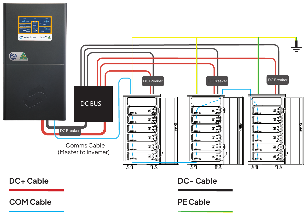
Cable legend:
| System start up | System shutdown |
|---|---|
| 1: Turn ON the DC breakers between the battery cabinet(s) and the inverter. | 1: Turn OFF the AC isolators (IN/OUT) on the inverter. |
| 2: Turn ON the battery module breakers. | 2: Turn OFF the PV isolators on the inverter and shut down the inverter. |
| 3: Press the ON/OFF button on the master battery for 1 second to power up the system. | 3: Turn OFF the DC breaker between the battery cabinet(s) and the inverter. |
| 4: Turn ON the PV and AC isolators and start the inverter. | 4: Press and hold the ON/OFF button on the master battery for 3 seconds to shut down the system. |
| 5: Check that the LEDs on all batteries are off, then turn OFF the battery module breakers. |
If you have any questions or need support, contact AERL.
Sincerely,
The AERL Team
AERL Pty Ltd · 1/75 Bluestone Circuit, Seventeen Mile Rocks QLD 4073 · 1800 950 865 · [email protected] · aerl.com.au
Australian Energy Research Laboratories
1/75 Bluestone Circuit
Seventeen Mile Rocks QLD 4073
Australia