 Download PDF· Rev 2.0.2
Installation and Operation Manual
AERL LiFe² 5120S
5.12 kWh LFP Battery and Battery Cabinets
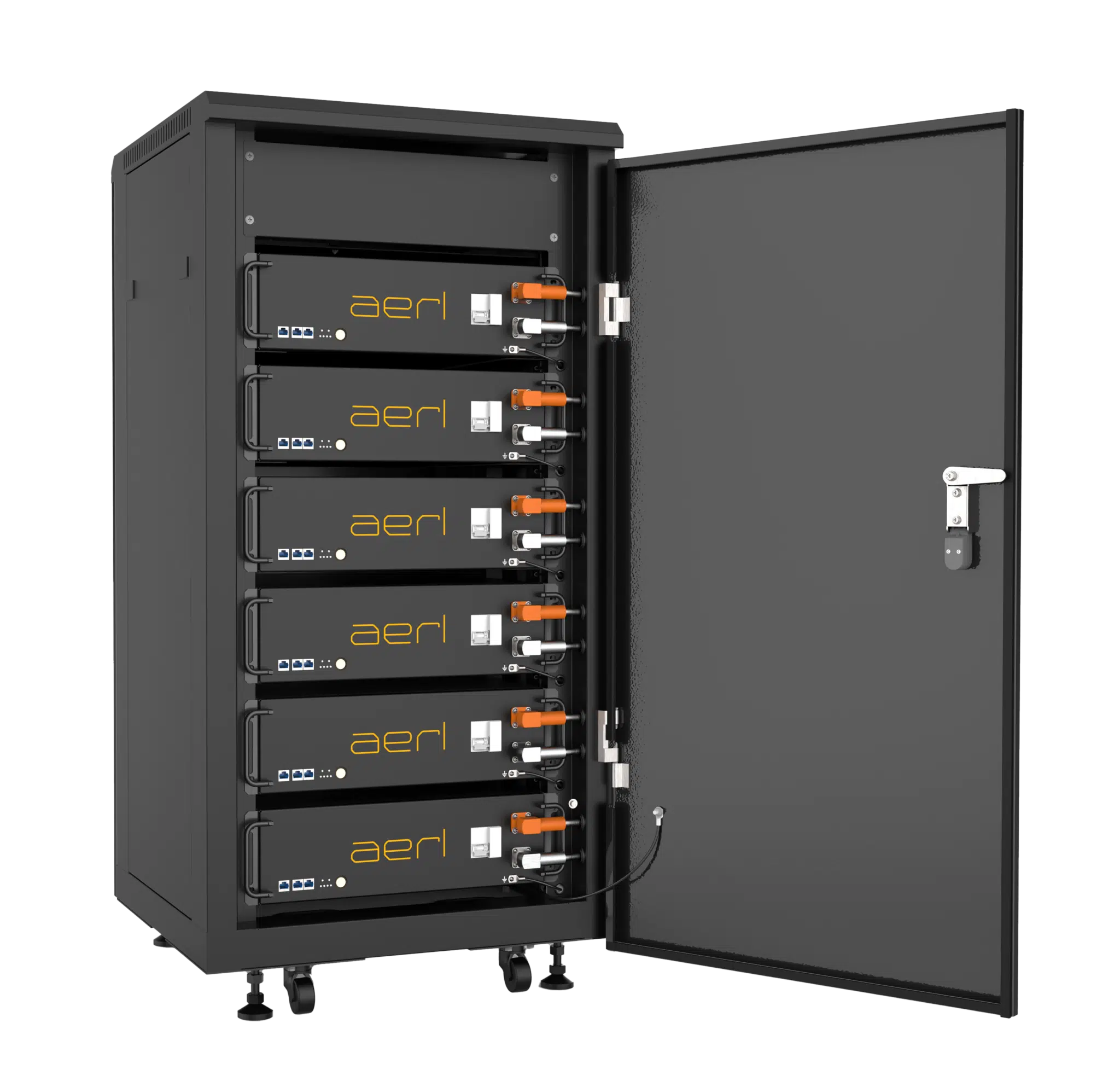
LiFe²-5120S · LiFe² battery cabinets
Installation and Operation ManualRev 2.0.2, 8 Nov 2026
Download PDF· Rev 2.0.2
Installation and Operation Manual
5.12 kWh LFP Battery and Battery Cabinets
The LiFe² 5120S is a 5.12 kWh lithium iron phosphate (LFP) battery for off-grid and backup systems. It balances its cells actively and runs in two modes: Managed and Self-Managed. The module is a 19-inch rack-mount unit: install it in a standard 19-inch rack or in an AERL pre-wired battery cabinet.
Up to 64 LiFe² 5120S modules can be connected in parallel, for a system capacity of up to 327.68 kWh. With a supported inverter, the battery is managed over CAN bus (Managed mode) and falls back to Self-Managed mode automatically if communication with the inverter is lost. Without communication, the LiFe² 5120S works in Self-Managed mode with third-party power conversion equipment (PCE): hybrid inverters, battery chargers and MPPT solar charge controllers.
The LiFe² 5120S can be hot-swapped and has an integrated circuit breaker for isolation. The Battery Management System (BMS) monitors the breaker and can trip it electronically, in addition to the breaker's own overcurrent protection.
The battery discharges at temperatures down to −20 °C and charges down to −10 °C.
This manual covers the installation and operation of the LiFe² 5120S battery and the LiFe² battery cabinets.
| Term | Meaning |
|---|---|
| BESS | Battery Energy Storage System |
| BMS | Battery Management System |
| DOD | Depth of Discharge |
| LED | Light Emitting Diode |
| LFP | Lithium Iron Phosphate (LiFePO4) |
| PCE | Power Conversion Equipment (inverters, chargers and charge controllers) |
| SOC | State of Charge |
| SOH | State of Health |
Follow the safety requirements in this manual when installing, commissioning, operating and maintaining the product. Incorrect operation or handling can damage the product and other property, or cause injury or death to the operator or others.
When securing the product with screws or other fasteners, use the correct tools and tighten to the torque given in this manual or on the product label. Incorrect torque can make the product unstable or damage it.
Make sure you know how to use each tool correctly before you start, to prevent injury.

Read this manual in full before installation, so that the product is installed and used safely and correctly.
Ship LiFe² 5120S batteries with the terminals covered, to prevent contact with metal objects and short circuits. To comply with international transport regulations, the batteries are discharged to a low SOC before shipping.
Wherever possible, ship batteries in the original packaging, horizontal and firmly fastened to a pallet. Do not ship batteries on end, and do not stack more than six.
Check the voltage of LiFe² 5120S batteries that have been stored for 6 months or more:
Stop using a damaged battery immediately, and dispose of it safely or return it to the manufacturer. A damaged battery can leak electrolyte, which may cause breathing difficulties, skin irritation and chemical burns. If you come into contact with electrolyte:
A battery fire may occur if the battery is too close to a flame or the ambient temperature is unusually high. A burning battery may release carbon monoxide, carbon dioxide and other gases, and smoke.
If the battery has been submerged in water, stop using it immediately and contact AERL. If you must disconnect power, or you are in the same water as the battery, first put on rubber gloves and boots to protect yourself from electric shock.
The LiFe² 5120S has an integrated Battery Management System (BMS) that monitors the battery continuously and protects it against harmful conditions.
The BMS provides:
The integrated circuit breaker is electronically controlled, so the BMS can isolate the battery quickly when it detects a fault or unsafe operating condition.
Each LiFe² 5120S battery is supplied with all the cables needed to install it in a LiFe² pre-wired battery cabinet.
| # | Part | Qty |
|---|---|---|
| 1 | Termination Plug | 1 |
| 2 | Comms Cable | 1 |
| 3 | M6 × 16 Bolt | 4 |
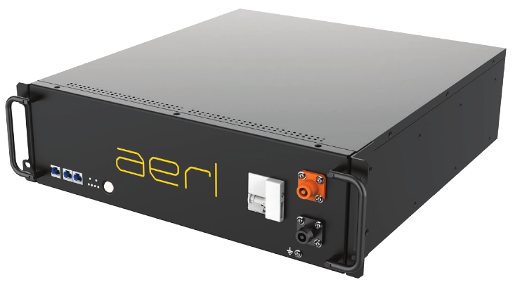

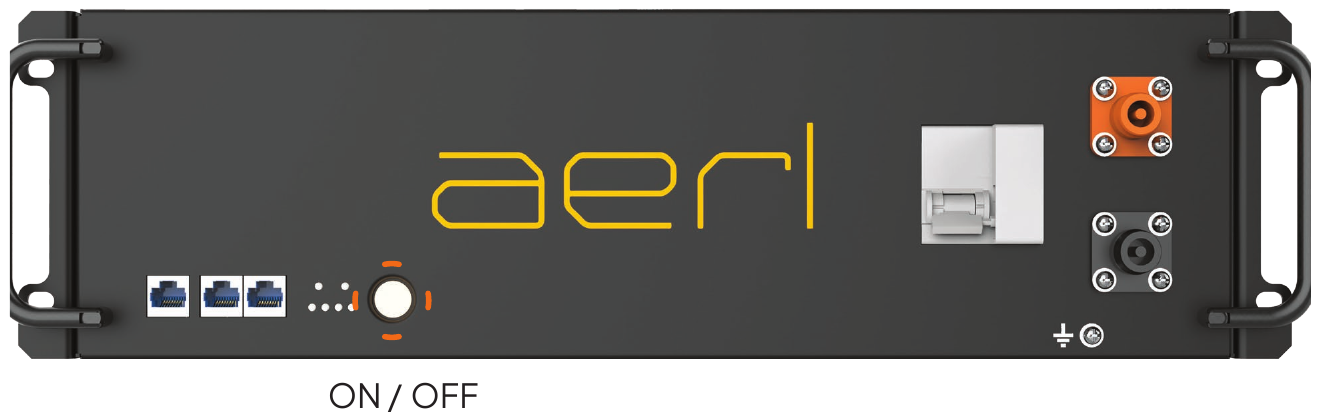
The front-panel LEDs show the battery state (Status, Error and SOC) at a glance.
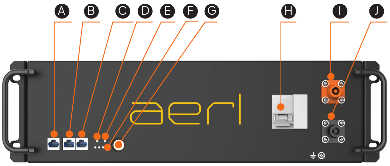
| Letter | Label | Function |
|---|---|---|
| A | COMM | Inverter Comms |
| B | OUT | Battery Comms Out |
| C | IN | Battery Comms In |
| D | N/A | Error Indication |
| E | N/A | Battery Status |
| F | N/A | SOC Indicator |
| G | ON/OFF | On/Off Switch |
| H | MCB | Circuit Breaker |
| I | + | DC+ Port |
| J | − | DC− Port |
| Parameter | Battery specification |
|---|---|
| Part Number | LiFe²-5120S |
| Nominal Voltage | 51.2 V DC |
| Operating Voltage Range | 40.8 V DC to 58.4 V DC |
| Capacity | 5.12 kWh / 100 Ah |
| Depth of Discharge | Up to 100% |
| Maximum Continuous Discharge Rate | 1C (@ 25 °C) |
| Maximum Continuous Discharge Current | 100 A (@ 25 °C) |
| Parameter | Battery specification |
|---|---|
| Maximum Discharge Power | 5.12 kW |
| Peak Discharge Current | 200 A (10.24 kW, 5 s) |
| Maximum Continuous Charge C-Rate | 1C (@ 25 °C) |
| Maximum Continuous Charge Current | 100 A (@ 25 °C) |
| Peak Charge Current | 200 A (@ 25 °C) |
| Integrated Circuit Breaker | 2-pole, 125 A, 80 V DC |
| Lithium Chemistry | LiFePO4 / LFP |
| Cell Construction | Prismatic |
| Operating Temperature Range, Managed | Charge: −10 to 55 °C / Discharge: −20 to 55 °C |
| Operating Temperature Range, Self-Managed | Charge: 0 to 55 °C / Discharge: −5 to 55 °C |
| Operating Humidity | Up to 95% (non-condensing) |
| BMS Over-Voltage Cell Level Protection | 3.65 V DC |
| BMS Under-Voltage Cell Level Protection | 2.55 V DC |
| BMS Over-Temperature Cut-Off | 56 °C |
| Short Circuit Current | 2000 A |
| Arc Flash Incident Energy (IEm at 45 cm) | 0.341 cal/cm² |
| Arc Flash Boundary (AFB) | 23.952 cm |
| Altitude | < 2500 m |
| DC Connectors | 125 A Quick Connect |
| IP Rating | IP20 |
| Efficiency | > 96% |
| Cooling | Natural Convection |
| Scalability | 64 Batteries in Parallel |
| Series Connection | Not Permitted |
| Communications | CAN 2.0A / RS485 / No Comms |
| Weight | 44 kg |
| Dimensions (W × H × D) | 440 × 134 × 480 mm |
| Warranty | 5 years; 10 years if registered within 60 days of installation. Conditions apply: see the LiFe² Warranty Statement |
| Certifications, Cell | UL 1973, UL 9540A, IEC 62619:2022, UN 38.3 |
| Certifications, Pack | IEC 62619:2022, IEC 62040-1, UN 38.3, CE |
| Country of Manufacture | People's Republic of China |
| Parameter | LiFe²-CAB6 | LiFe²-CAB10 | LiFe²-CAB4-OUTD | LiFe²-CAB6-OUTD | LiFe²-CAB10-OUTD |
|---|---|---|---|---|---|
| Dimensions (W × H × D) | 620 × 1270 × 600 mm | 620 × 1890 × 600 mm | 580 × 1380 × 400 mm | 680 × 1240 × 700 mm | 680 × 1800 × 700 mm |
| Fixing | 4 × wheels, 4 × feet | 4 × wheels, 4 × feet | 4 × bolt points, 4 × lift points | 4 × bolt points, 4 × lift points | 4 × bolt points, 4 × lift points |
| Max. Module Quantity | 6 (30.72 kWh) | 10 (51.20 kWh) | 4 (20.48 kWh) | 6 (30.72 kWh) | 10 (51.20 kWh) |
| Busbar Continuous Current Rating | 625 A | 1250 A | 250 A | 400 A | 600 A |
| Battery Interconnection | Pre-wired quick connector, 4 AWG UL cable | Pre-wired quick connector, 4 AWG UL cable | Pre-wired quick connector, 4 AWG UL cable | Pre-wired quick connector, 4 AWG UL cable | Pre-wired quick connector, 4 AWG UL cable |
| DC Circuit Breaker | None | None | None | None | None |
| IP Rating | IP20 (indoor) | IP20 (indoor) | IP55 (outdoor) | IP55 (outdoor) | IP55 (outdoor) |
| Weight | 91 kg | 128 kg | 52 kg | 135 kg | 142 kg |
| Warranty | 2 years | 2 years | 2 years | 2 years | 2 years |
Cabinet warranty conditions: see the LiFe² Warranty Statement.
This chapter sets out how to install the LiFe² battery and cabinets safely. Correct installation is essential for the system's life, efficiency and safe operation.
Choose the installation location carefully. If you are not using a LiFe² battery cabinet, install the battery in a 19-inch data rack or another compliant, secure electrical enclosure. The IP20 cabinets (LiFe²-CAB6 and LiFe²-CAB10) are for indoor use only.
The location must be:
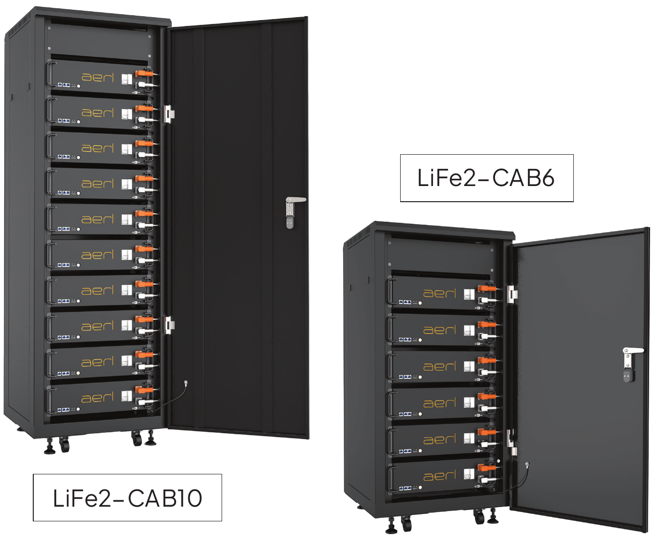
The LiFe² batteries fit a 600 mm deep 19-inch equipment rack. AERL's pre-wired cabinets hold 6 or 10 batteries indoors (LiFe²-CAB6, LiFe²-CAB10, IP20) and 4, 6 or 10 batteries outdoors (LiFe²-CAB4-OUTD, LiFe²-CAB6-OUTD, LiFe²-CAB10-OUTD, IP55).
The pre-wired cabinets save installation time and are the recommended solution.
If you design and build your own battery enclosure:

Use pre-assembled cables to connect the batteries to a custom cabinet busbar (or similar). Order them from AERL as part number AERL-BATT-CABLE-2.5.
The LiFe² 5120S has Exconn (non-keyed) connectors on its positive and negative terminals. To parallel several cabinets you may need additional power cables, combined through a DC busbar assembly or a DC combiner box. Use power cables of the same length throughout, so that every battery sees the same impedance.
You need the following tools to install the LiFe² 5120S:
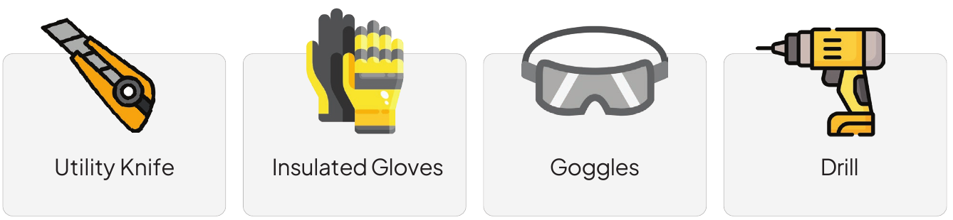
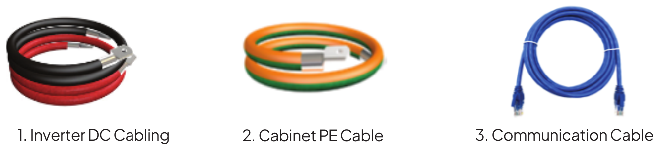

Check the local requirements for battery installations. They differ between countries and jurisdictions, and many require DC isolation between the battery cabinets and the inverter.
When the cabinet arrives, inspect it inside and out for damage. If you find any, contact your supplier.
Sections 5.6 and 5.7 describe the indoor cabinets (LiFe²-CAB6, LiFe²-CAB10), which have caster wheels and support feet. The outdoor cabinets have no wheels or feet: lift them by their four lift points and fix them through their four bolt points.
Minimum clearances:
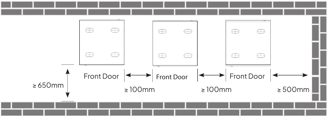
Indoors, leave at least 25 mm between the top of the cabinet and the ceiling.
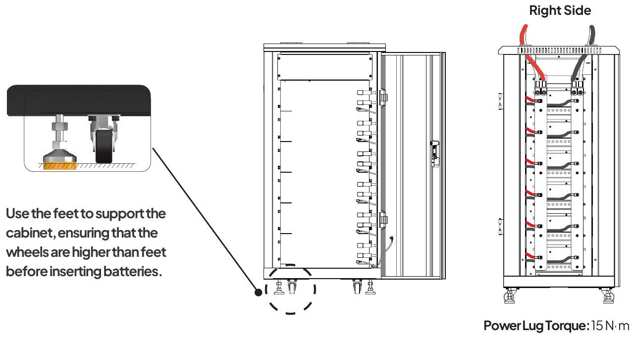
When the cabinet is in its final position, lower the load-bearing feet fully before you insert any batteries, so that the feet carry the weight and the wheels are off the floor.
The main DC busbar is behind the removable panel on the right side of the cabinet. Remove the internal securing screw and lift the panel off to reach the busbar. Torque all connections, then refit the panel.
Power Lug Torque: 15 N·m
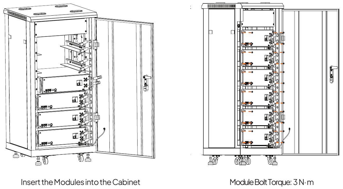
Starting at the bottom of the cabinet, slide the battery modules in one at a time until the cabinet is full or you have installed the number required. Secure each module with the supplied screws.
Module Bolt Torque: 3 N·m
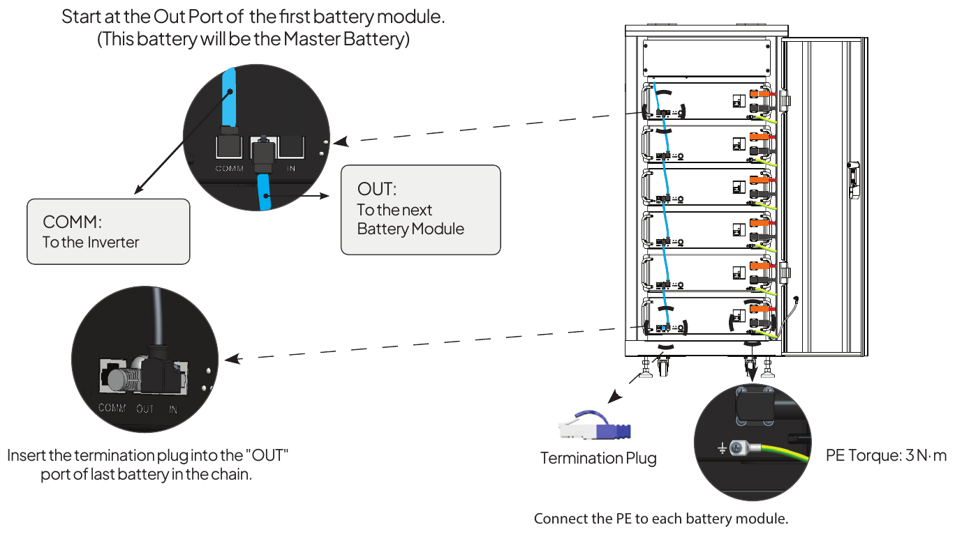
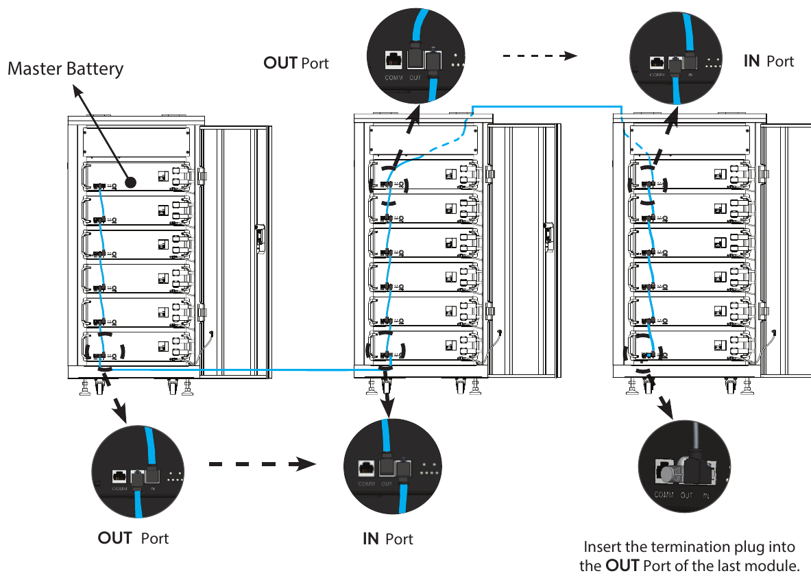
The first battery module in the chain is the master battery.
Insert the termination plug into the OUT port of the last battery in the chain.
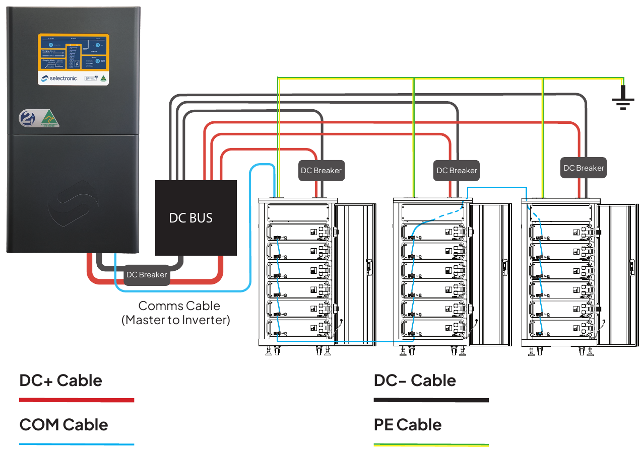
Connect the PE to each battery module.
PE Torque: 3 N·m
The LiFe² 5120S has a built-in 2-pole 125 A / 80 V DC breaker.
To comply with AS/NZS 5139, all live battery conductors must also pass through 2-pole MCCBs installed between the battery modules and the inverter or DC bus.
Connect the main DC cables to the inverter's positive and negative terminals as the inverter manufacturer instructs.
Cable legend:
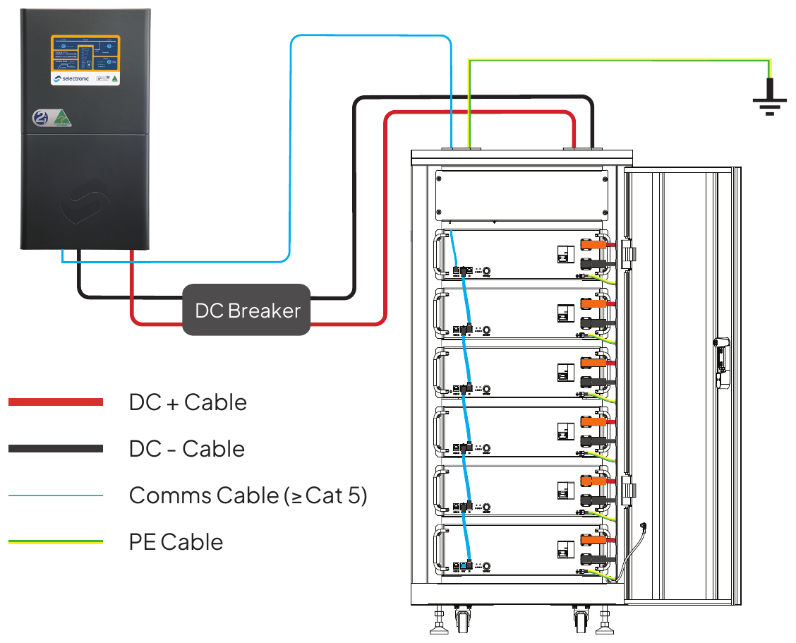
The comms cable must be Cat 5 or higher.
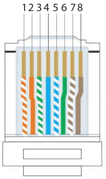
Master Comms Port Pin-Out
| PIN No. | Definition |
|---|---|
| 1 | NC |
| 2 | NC |
| 3 | NC |
| 4 | CAN_H |
| 5 | CAN_L |
| 6 | NC |
| 7 | RS485B |
| 8 | RS485A |
In Self-Managed (No Comms) mode, the LiFe² 5120S runs without communication, with third-party charging sources whose charge settings can be configured. In this mode the LiFe² can replace a lead-acid battery.
The LiFe² 5120S starts in Managed (communication) mode by default.
Use Self-Managed mode when the inverter has no communication link to the battery (a no-comms or Self-Managed PCE). To switch to Self-Managed (No Comms) mode: with the battery on, double-press the ON/OFF button on the master battery. The SOC LEDs flash 3 times to confirm. The battery remembers the mode after a restart, so you set it once.
The battery switches back to Managed mode automatically when the communication cable between the inverter and the master battery is connected.
If one cabinet does not provide enough storage, connect several cabinets in parallel.
The diagram below shows how to connect the communication chain across several cabinets.
Insert the termination plug into the OUT port of the last module.
Cable legend:
The LiFe² 5120S LEDs show the status of the battery.
| LED | Status | Description |
|---|---|---|
| Error | Red ON | An error has occurred. |
| Error | Off | There are no active errors. |
| Status | Green ON | The battery is active and can be charged and discharged. |
| Status | Off | The battery is not active. |
| SOC | 4 LEDs ON | 75–100% SOC |
| SOC | 3 LEDs ON | 50–75% SOC |
| SOC | 2 LEDs ON | 25–50% SOC |
| SOC | 1 LED ON | 0–25% SOC |
The integrated circuit breaker of the LiFe² 5120S:
Before you power up the system, check the installation:
Start up the battery system as recommended by the PCE manufacturer and this manual, and in line with local and government safety requirements.
| System start up | System shutdown |
|---|---|
| 1: Turn ON the DC breakers between the battery cabinet(s) and the inverter. | 1: Turn OFF the system AC isolators (if any). |
| 2: Turn ON the battery module breakers. | 2: Turn OFF the system PV isolators (if any) and shut down the inverter. |
| 3: Press the ON/OFF button on the master battery for 1 second to power up the system. | 3: Turn OFF the DC breakers between the battery cabinet(s) and the inverter. |
| 4: Turn ON the system PV isolators (if any). | 4: Press and hold the ON/OFF button on the master battery for 3 seconds to power down the system. |
| 5: Turn ON the system AC isolators (if any) and start the inverter. | 5: Check that the LEDs on all batteries are off, then turn OFF the battery module breakers. |
The LiFe² 5120S discharges down to −20 °C and charges down to −10 °C.
The battery delivers 100 A continuously and 200 A peak for up to 5 seconds. Do not charge at more than 100 A.
Charge to 100% SOC regularly, to keep the SOC accurate:
LiFe² 5120S batteries are shipped at a low SOC, as international shipping regulations require.
When you first power up the system, charge it to 100% SOC to calibrate the SOC. This matters most in self-managed applications, where the connected PCE must learn the battery's SOC.
SOC drift is the error that builds up in the SOC calculation over time, from tolerances in the voltage and current measurements and in the capacity algorithm. Most systems reset this error when the battery reaches 100% SOC or enters float.
To limit SOC drift, the battery should reach float or 100% SOC regularly, ideally every 1 to 3 days:
Remote monitoring is available through AERL Cloud with a Nexus Gateway, or through third-party inverter platforms.
Scan the QR code to learn how to connect your battery system.

The battery itself needs no maintenance. Check the system regularly:
Additional LiFe² 5120S batteries can be added to an existing installation at any time during the warranty period. All batteries must be of the same type and part number. If you are unsure, contact AERL after-sales support.
New batteries can be added at any SOC or voltage. The system balances itself, bringing the new battery to the SOC and voltage of the existing bank.
In Self-Managed mode, update the battery capacity in all PCE settings.
Different battery types or capacities cannot be mixed in a rack. All batteries in a rack must have the same type, part number and specification, unless AERL advises otherwise.
If a battery module reaches 0% SOC and its voltage falls below 40 V (over-discharge), recharge it in one of these ways:
If a battery has shut down automatically after a long period without charging, recharge it within 10 days to restore a healthy SOC.
When a LiFe² 5120S battery reaches the end of its life:
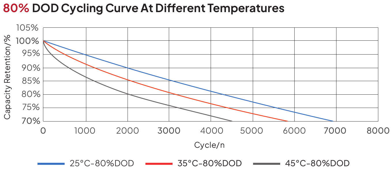
Capacity retention (%) against cycle count at 25 °C, 35 °C and 45 °C, 80% DOD. All curves start at 100% retention and trend down toward 70% retention: 25 °C at ~7000 cycles; 35 °C at ~5500 cycles; 45 °C at ~4500 cycles.
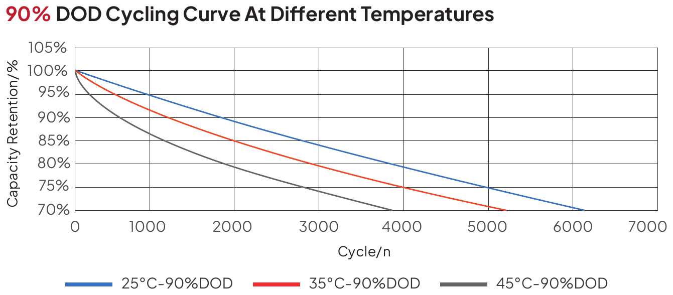
At 90% DOD, the 25 °C curve reaches ~70% retention at approximately 6000 cycles; 35 °C at ~5000 cycles; 45 °C at ~4000 cycles.
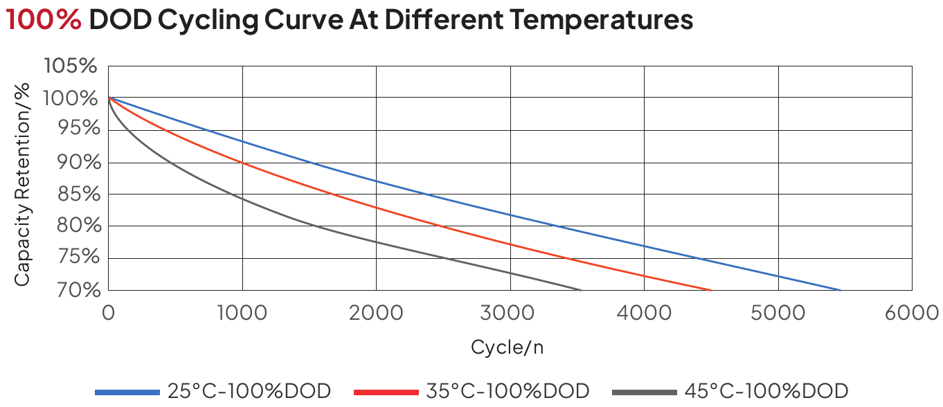
At 100% DOD, the 25 °C curve reaches ~70% retention at approximately 5500 cycles; 35 °C at ~4500 cycles; 45 °C at ~3500 cycles.
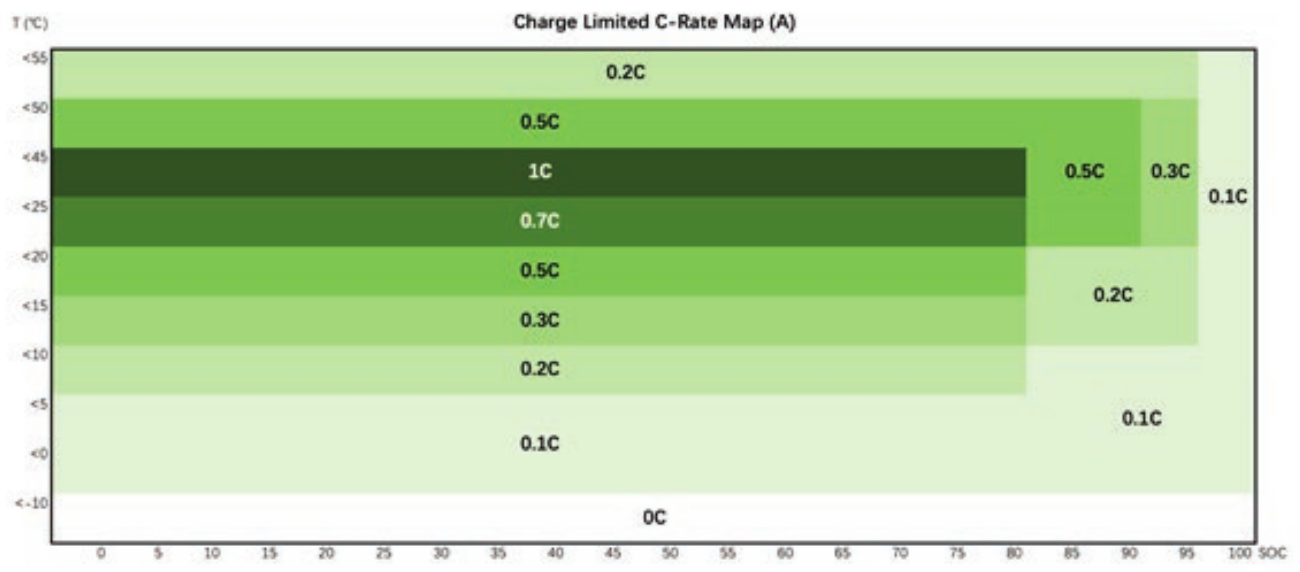
Permitted charge C-rate bands by temperature:
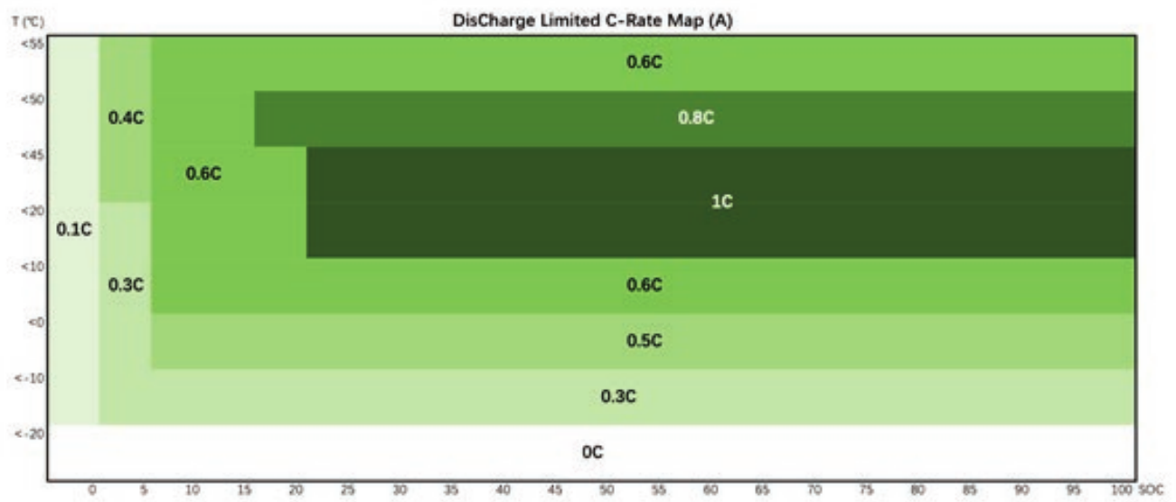
Permitted discharge C-rate bands by temperature:
If you have any questions or need support, contact AERL.
Sincerely,
The AERL Team
AERL Pty Ltd · 1/75 Bluestone Circuit, Seventeen Mile Rocks QLD 4073 · 1800 950 865 · [email protected] · aerl.com.au
Australian Energy Research Laboratories
1/75 Bluestone Circuit
Seventeen Mile Rocks QLD 4073
Australia