01Confirm the SP PRO Supports ModbusSP LINK checks, comms card revisions, Port 102
02Wiring and Switching on ModbusRS485 patch lead, termination, SP LINK settings03
03Getting the Nexus OnlineNetwork wizard, claim gateway, customer access04
04Adding the SP PRO in AERL CloudModbus device, telemetry groups, update cadence05
05TroubleshootingTx/Rx LED diagnostics, bus sharing, support06
06Managed Batteries & Final ChecklistCAN bus, commissioning summary, contact07
AERL Nexus · SP PRO Setup
Installer GuideRev 1.0.209 November 2026
Chapter 01
Confirm the SP PRO Supports Modbus
Open SP LINK, connect to the inverter, and perform the following checks.
Inverter Details Checks
Go to Data View → Inverter Details and confirm all of the following:
#
Requirement
1
The inverter is a Series 2i (or equivalent newer model).
2
The Comms Card Revision is 8 or higher. This card is called the “ACC”.
3
The SP PRO firmware is V14.47 or newer.
4
The ACC firmware is V4.31 or newer.
Then physically locate the RJ45 socket on the SP PRO comms card labelled Port 1.
AERL Nexus · SP PRO Setup
Installer GuideRev 1.0.209 November 2026
Chapter 02
Wiring and Switching on Modbus
The Cable
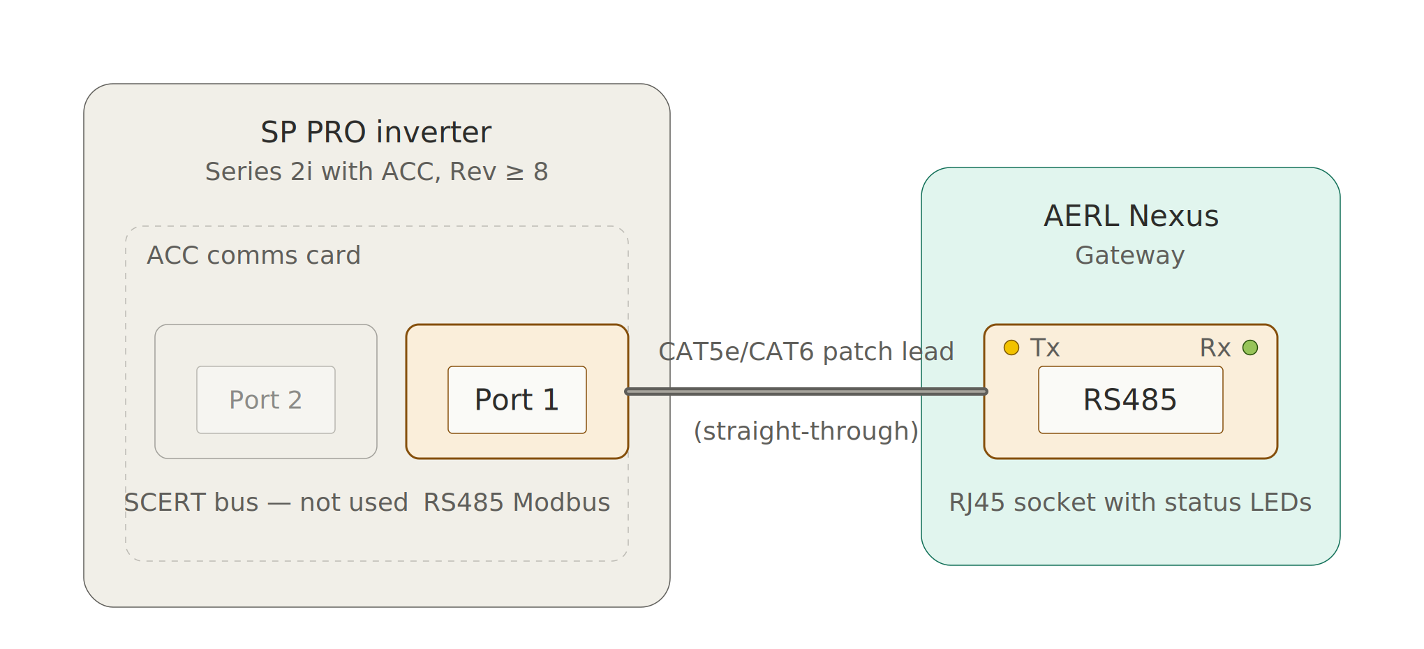
The SP PRO and the Nexus use the same RJ45 wiring layout, so a normal straight-through CAT5e or CAT6 patch lead is required. Plug one end into Port 1 on the Selectronic ACC and the other into the Nexus's RS485 socket.
Keep the run short
Ensure the Nexus is installed as close as possible to the SP PRO.
SP PRO ACC Port 1 → Nexus RS485
Turning Modbus On
The SP PRO ships with Modbus switched off. To enable it in SP LINK:
Go to Configuration Settings → System → Communication.
Set the serial parameters — these must match what the Nexus expects:
Comm Card Input: Internal (RJ45)
Modbus Address:1
Baud rate:9600
Modbus port: 8 data bits, 1 stop bit, no parity (written as 8 bit, None 1 stop)
Save and upload the new config to the SP PRO.
PowerChain systems
On a PowerChain system, the connection and setting should be done on the PowerChain master.
AERL Nexus · SP PRO Setup
Installer GuideRev 1.0.209 November 2026
Chapter 03
Getting the Nexus Online
Plug It in and Get It Online
Connect the Nexus's RS485 port to the SP PRO if not already done.
Plug an Ethernet cable into the Nexus's network port from your internet router.
Power the Nexus on.
As soon as the Nexus detects the Ethernet link, it automatically connects to AERL Cloud.
Sign in. If you don't have an organisation set up yet, create one for the site.
Click Add Gateway on the dashboard or the Gateways page (or the + button in the top bar).
On Claim Your Gateway, enter the serial number and pin code from the sticker on the Nexus, then click Claim Gateway. AERL Cloud adds the gateway to your organisation.
Assign the gateway to a location — pick an existing one or create a new one with the site address and coordinates.
Providing Customer Access
To give the customer access, go to Organisation → Invitations and invite them.
Wrong account claimed
If a gateway has been claimed by the wrong account by mistake, contact AERL support.
AERL Nexus · SP PRO Setup
Installer GuideRev 1.0.209 November 2026
Chapter 04
Adding the SP PRO in AERL Cloud
Add the Inverter as a Modbus Device
You need the Owner or Admin role in the organisation. In the AERL Cloud web app, go to Gateways and click Manage beside your Nexus. In Edit Gateway, under Modbus Devices, click Add Device.
Device Product: pick Selectronic SP PRO from the dropdown.
Click Add Device. The Nexus is automatically configured to connect to the SP PRO via its RS485 port.
The Nexus should download new config from the cloud within about five minutes. You don't need to restart the device.
Make sure the SP PRO's Modbus settings in SP LINK (slave 1, 9600, 8N1 — see Chapter 02) match the defaults the Nexus expects.
Sole master on the comms link
The Nexus Gateway does not support other Modbus master devices on the comms link with the SP PRO.
Confirming Data Is Being Received
Within about five minutes of saving, inverter data should start appearing in the gateway view. You'll see readings grouped as:
Group
Readings
Battery
Voltage, state of charge, power, current, temperature.
AC Load
Power, voltage, frequency, accumulated energy.
AC Source (grid or generator)
Power, voltage, current, frequency, reactive power, total imports and exports.
AC Inverter
Power, current, reactive power.
Output state
Off, Econo, On, or Synchronised.
Battery charging state
Normal, Override, Off, Renewable, or Restricted.
Thermal readings
Battery, transformer, and heatsink temperatures.
Config apply≤ 5 min
Telemetry · Ethernet1 min
Telemetry · cellular10 min
WAN typeAuto-detect
How often data is sent depends on how the Nexus connects to the internet. The Nexus automatically determines which type of connection it has. It sends data every minute when connected via Ethernet and every ten minutes via cellular.
AERL Nexus · SP PRO Setup
Installer GuideRev 1.0.209 November 2026
Chapter 05
Troubleshooting
More detailed help
Refer to the SP PRO Manual, §4.3.1 for more detailed troubleshooting.
The Nexus has two status LEDs next to its RS485 socket, labelled Tx and Rx. Tx flickers when the Nexus sends a Modbus request; Rx flickers when the SP PRO replies. Use these LEDs (on the Nexus, not the SP PRO) to diagnose the link.
Symptom on the Nexus
Likely cause & what to check
Tx LED isn't flickering
The Nexus itself isn't polling. Check that the Nexus shows as online in AERL Cloud and that the Modbus device entry exists.
Tx flickers but Rx doesn't
The Nexus is sending requests but the SP PRO isn't replying. Check the cable is connected to Port 1 on the ACC, that you're using a straight-through Ethernet cable (not one with Rx/Tx swapped), and that the ACC's power LED is on. If the wiring is good, likely causes are: wrong slave address, wrong baud rate, wrong format, Modbus not actually saved as enabled in SP LINK, firmware too old, or an internal comms fault on the SP PRO itself. If SP LINK shows an attention flag saying “Inverter, No response on Com Card Internal Link Port 2”, contact Selectronic service.
Both LEDs flicker but no data in the cloud
The electrical link is working but the configuration in AERL Cloud probably doesn't match the SP PRO's settings. Double-check the slave ID, baud rate, and that you picked the right product profile in Edit Gateway. If everything looks right, contact AERL support with the Nexus serial number and a screenshot of the SP LINK Inverter Details page.
When to Involve AERL Support
If the LED test looks healthy but data still isn't flowing, AERL support can run a bus-discovery check on the Nexus from our end. That separates “is the electrical connection working” from “is the cloud configuration right”. When you raise a ticket, give us the Nexus serial number and a quick note on what the LEDs are doing.
No Support for Multiple Modbus Masters
The Nexus expects to be the only device polling the SP PRO. If there is another Modbus master on the same wires (another gateway, a data logger, or a remote screen interface), the devices will interfere with each other. Connect the other device to another comms card or inverter.
AERL Nexus · SP PRO Setup
Installer GuideRev 1.0.209 November 2026
Chapter 06
Managed Batteries & Final Checklist
CAN Bus and Managed Batteries
Some installations also have a battery management system talking to the SP PRO over CAN bus. The Nexus automatically supports managed batteries over CAN bus; there is nothing to set up. If you connect the Nexus to that bus, CAN 1 and CAN 2 are linked internally, so it can sit inline. The Nexus has no built-in termination: if it is at an end of the bus, fit a 120 Ω RJ45 termination plug in its unused CAN socket.
Random comms dropouts
Ensure the Nexus is on the latest firmware before raising a ticket.
Quick Commissioning Checklist
Confirm the SP PRO is suitable: ACC Rev 8 or higher, firmware V14.47 and V4.31 or newer, Series 2i.
Run a CAT5e or CAT6 patch lead from the SP PRO's ACC Port 1 to the Nexus's RS485 socket.
In SP LINK, turn on Modbus. Slave 1, 9600 baud, 8N1.
Plug an Ethernet cable into the Nexus and power it on.
Claim the gateway in AERL Cloud using the serial number and pin code from the sticker.
Add the Modbus device: pick Selectronic SP PRO as the Device Product and click Add Device.

 AERL Nexus