---
title: "Solinteg M2HT 25–50 kW — Paralleling & Generator Guide"
revision: "1.0.2"
publisher: AERL (Australian Energy Research Laboratories)
url: https://www.aerl.com.au/docs/solinteg-m2ht-25-50-paralleling-dg-guide
pdf: https://www.aerl.com.au/documents/guides/Hybrid_Inverter_25-50kW_Paralleling_Generator_Guide_REV_102.pdf
description: "Design, wiring and app set-up for parallel systems of up to ten M2HT 25–50 kW inverters (500 kW), and for adding a diesel generator with the Solinteg EDA back-up box and an ATS."
---
# Solinteg M2HT 25–50 kW — Paralleling & Generator Guide
*Rev 1.0.2. Markdown copy of the AERL document at https://www.aerl.com.au/docs/solinteg-m2ht-25-50-paralleling-dg-guide; the PDF (https://www.aerl.com.au/documents/guides/Hybrid_Inverter_25-50kW_Paralleling_Generator_Guide_REV_102.pdf) is the controlled version.*
# Paralleling and Diesel Generator Solutions
Solinteg M2HT 25–50 kW Hybrid Inverters
**M2HT-25K · 29.9K · 30K · 40K · 50K** **Application Guide** Rev 1.0.2, 9 Nov 2026
## 01 Introduction — Overview, system types, solutions in this guide
### Document
| | |
|---|---|
| Revision | 1.0.2 (Australian edition) |
| Effective | 11 / 2026 |
| Audience | Designers and licensed installers |
| Inverters in parallel | Up to 10 (500 kW) |
| Generator size | At least 1.5 × total inverter power |
| Extra hardware | EDA back-up box, ATS |
| App | Solinteg IntegHub |
| Format | A4 · 29 pages |
### 1.1 Overview
**Paralleling.** Up to ten Solinteg M2HT 25–50 kW hybrid inverters can run in parallel, on both the on-grid side and the back-up side, for a total of up to 500 kW. Parallel systems suit high-power sites such as factories, shopping centres and business parks, and keep the site supplied when the grid is unavailable or unstable. The inverters offer six work modes, including time-of-use (ToU), to reduce energy costs.
**Diesel generator solutions.** Where the grid is unreliable, a diesel generator (DG) adds a second power source, so the site stays supplied during planned and unplanned outages. Solinteg offers generator solutions for single inverters, and for parallel systems using the Solinteg EDA back-up box and an automatic transfer switch (ATS). These cover applications from residential to commercial, with intelligent management of the whole system.
When the grid fails, the generator can supply the loads and also charge the battery, which makes the system more stable.
> **The generator and the inverters never supply the loads at the same time**
>
> Size the generator and the inverter system so that **each one on its own** can supply the full load.
> **Australian requirements**
>
> Design and install the system in accordance with AS/NZS 3000, AS/NZS 4777.1, AS/NZS 5139 and, for generators, AS/NZS 3010. Grid-connected systems need network approval, and multiple-inverter systems may need central protection. Check with the local network service provider before you design the system. All installation work must be done by licensed electrical workers.
### 1.2 System Types
| Type | Output | Definition | Application |
|---|---|---|---|
| Single | 25–50 kW | One inverter | With battery backup. Suits grid-connected and off-grid sites, and sites that need on/off-grid switching because of frequent outages. |
| On/off-grid parallel | 50–500 kW | Up to 10 inverters in parallel on both the on-grid side and the back-up side | System-level battery backup. Suits sites with frequent outages. Reduces reliance on the grid, and keeps the loads running when the grid is down. |
| Off-grid parallel | 50–500 kW | Up to 10 inverters in parallel on the back-up side | System-level battery backup. Suits off-grid sites only. Forms a microgrid supplied by PV and batteries. |
| On-grid parallel | 50–500 kW | Up to 10 inverters in parallel on the on-grid side | No system-level battery backup. Suits sites with a stable grid. Reduces electricity costs through peak/off-peak arbitrage or response to grid dispatch. |
### 1.3 Solutions in This Guide
| Type | Solution | Section |
|---|---|---|
| Single inverter | Generator on the inverter GEN port, with grid | 3.1 |
| Single inverter | Generator through an ATS, with grid | 3.2 |
| Single inverter | Generator on the inverter on-grid port, no grid | 3.3 |
| Off-grid parallel | Scenario 1: grid only | 3.4 |
| Off-grid parallel | Scenario 2: generator only | 3.5 |
| Off-grid parallel | Scenario 3: grid and generator | 3.6 |
| Off-grid parallel | Scenario 4: no grid, no generator | 3.7 |
| On-grid parallel | Grid and generator | 3.8 |
### 1.4 Equipment Required
Every solution uses Solinteg M2HT 25–50 kW inverters, a three-phase diesel generator that can be started and stopped by a dry-contact (DO) signal, and a Solinteg RMM smart meter (supplied with the inverter). The generator and ATS are sourced locally.
| Solution | Generator connects at | Grid | EDA back-up box | ATS | Firmware |
|---|---|---|---|---|---|
| Single inverter | GEN port | On-grid or off-grid | — | — | Confirm with AERL |
| Single inverter | On-grid port | Off-grid | — | — | Confirm with AERL |
| Single inverter | ATS | On-grid | — | Yes | Confirm with AERL |
| Off-grid parallel (back-up side) | On-grid port | Off-grid | Yes | — | Confirm with AERL |
| Off-grid parallel (back-up side) | ATS | On-grid | Yes | Yes | Confirm with AERL |
| On-grid parallel | ATS | On-grid | — | Yes | Confirm with AERL |
## 02 How the System Works — Off-grid paralleling, generator output modes
### 2.1 Off-Grid Paralleling
#### Master and slave control
- Up to 10 inverters can run in off-grid parallel.
- One master inverter controls scheduling and settings, and synchronises them to the slave inverters.
- The master shares the power on each phase evenly across the slaves, based on the load on each of the three phases.
#### Work modes
- With the grid present, any of the six work modes available to a single inverter can be selected. If the grid is lost, the system switches to off-grid operation automatically.
#### Rated power
- All the inverters in parallel must be the same model and power rating.
- The total power is P total = N × P single , where N is the number of inverters in parallel.
#### Faults
| Event | System response |
|---|---|
| A slave fails or trips on protection | The master isolates it and the system keeps running |
| The master fails | The whole system shuts down |
| A slave's battery fails | The system keeps running and treats that slave as having no battery |
| The master's battery fails | The system runs only while the master has PV power |
### 2.2 Generator Output Modes
| Output mode | What the generator does |
|---|---|
| Loads only | The generator supplies the loads only, when required. |
| Loads and battery | The generator supplies the loads first, and charges the battery with any spare capacity. Charge power = generator maximum output − load power. |
### 2.3 Generator Control Methods
| Control method | How it works |
|---|---|
| Manual | Start and stop the generator from the app. Recommended for first commissioning. |
| Automatic | The generator starts automatically when the grid fails, and stops when the grid returns. Not available when the generator is connected to the inverter on-grid port. |
| SOC | When the grid fails, the system supplies the loads from the battery first, and starts the generator when the battery state of charge (SOC) falls below the start setting. The generator stops when the grid returns or the SOC reaches the stop setting. |
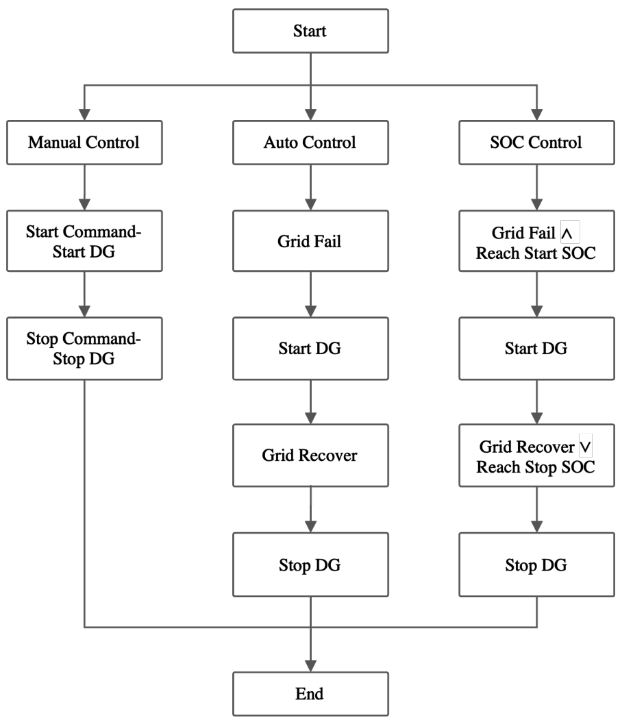
**Figure 2.1** Generator control logic for manual, automatic and SOC control.
> **Automatic generator start**
>
> Contact AERL for current support. Manual control is not affected.
## 03 Wiring — Single inverter, generator on the GEN port, with grid
All the wiring diagrams in this chapter use the same legend: DC, AC phase conductor, AC neutral, CAN, RS485, digital output (DO) and digital input (DI). Point the CT arrows towards the grid.
### 3.1 Single Inverter, Generator on the GEN Port, with Grid
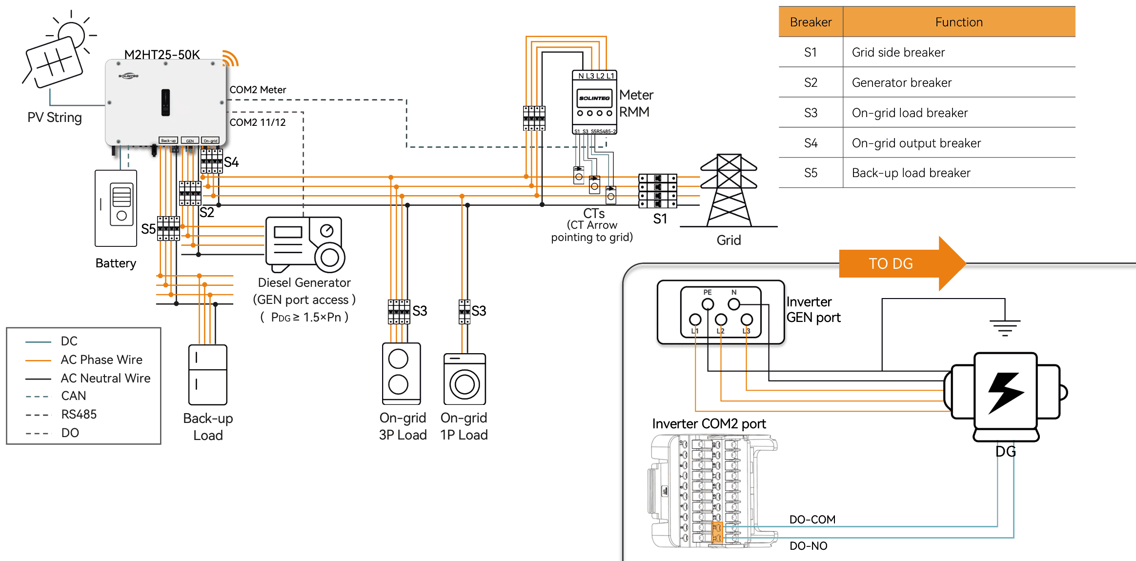
**Figure 3.1** Single inverter with the generator on the GEN port. The inset shows the generator start signal from COM2 (DO-COM, DO-NO).
| Breaker | Function |
|---|---|
| S1 | Grid-side breaker |
| S2 | Generator breaker |
| S3 | On-grid load breaker |
| S4 | Inverter on-grid output breaker |
| S5 | Back-up load breaker |
> **Before you design with this solution**
>
> The generator rating must be at least 1.5 × Ptotal.
### 3.2 Single Inverter, Generator Through an ATS, with Grid
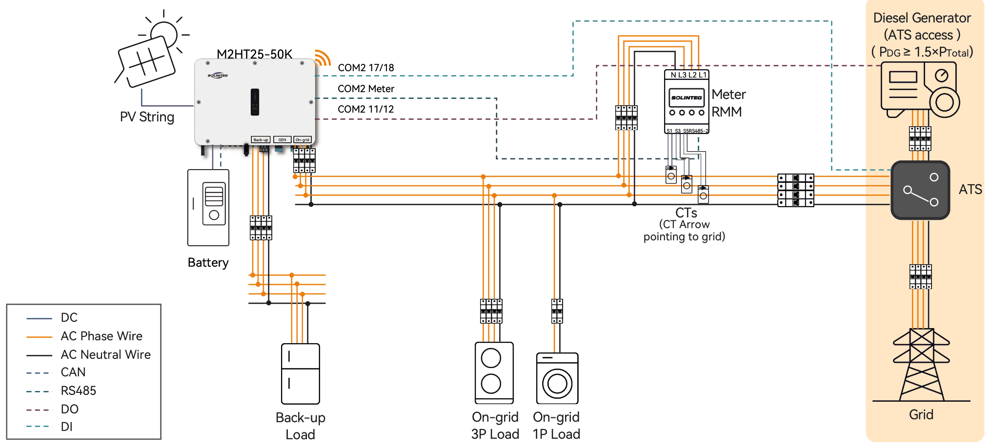
**Figure 3.2** Single inverter with the generator and grid switched by an ATS.
> **Before you design with this solution**
>
> This solution needs an ATS for reliable operation. The generator rating must be at least 1.5 × Ptotal.
### 3.3 Single Inverter, Generator on the On-Grid Port, No Grid
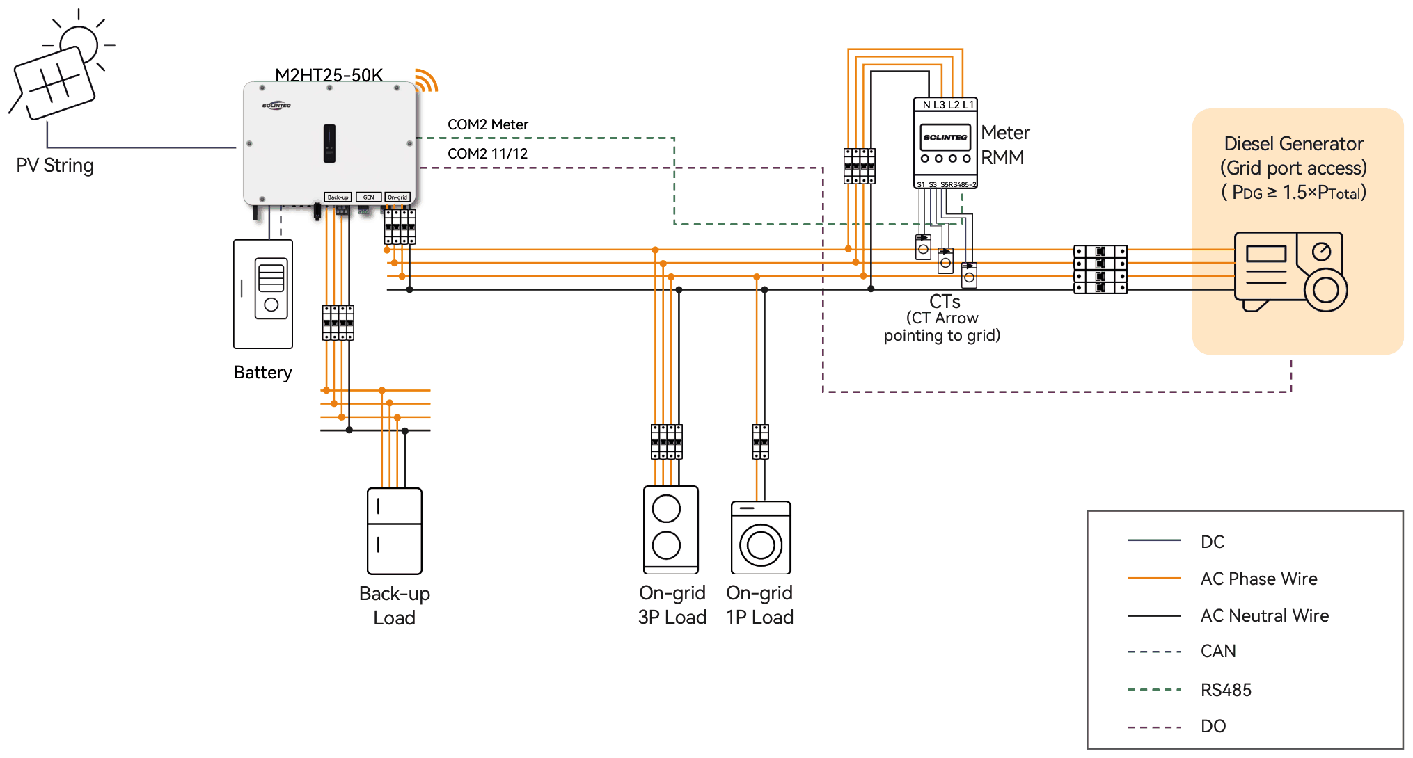
**Figure 3.3** Single inverter off-grid, with the generator connected at the inverter on-grid port.
> **Before you design with this solution**
>
> The generator rating must be at least 1.5 × Ptotal.
### 3.4 Off-Grid Parallel, Scenario 1: Grid Only
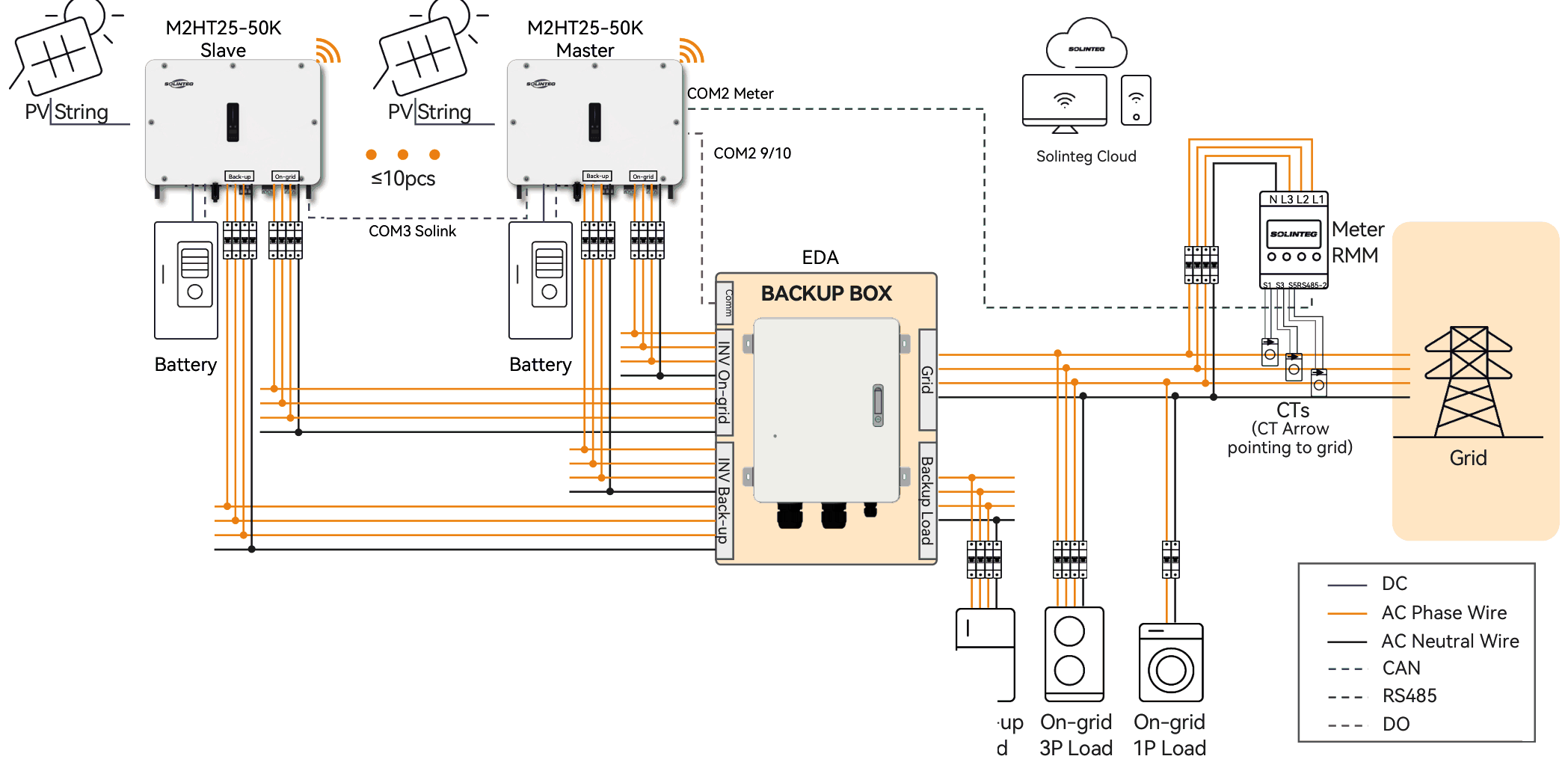
**Figure 3.4** Off-grid parallel with grid only. The EDA back-up box switches the back-up loads.
> **Before you design with this solution**
>
> This solution needs the EDA back-up box for reliable operation. All the inverters in parallel must be the same model and power rating. Otherwise the weakest inverter limits the whole system.
### 3.5 Off-Grid Parallel, Scenario 2: Generator Only
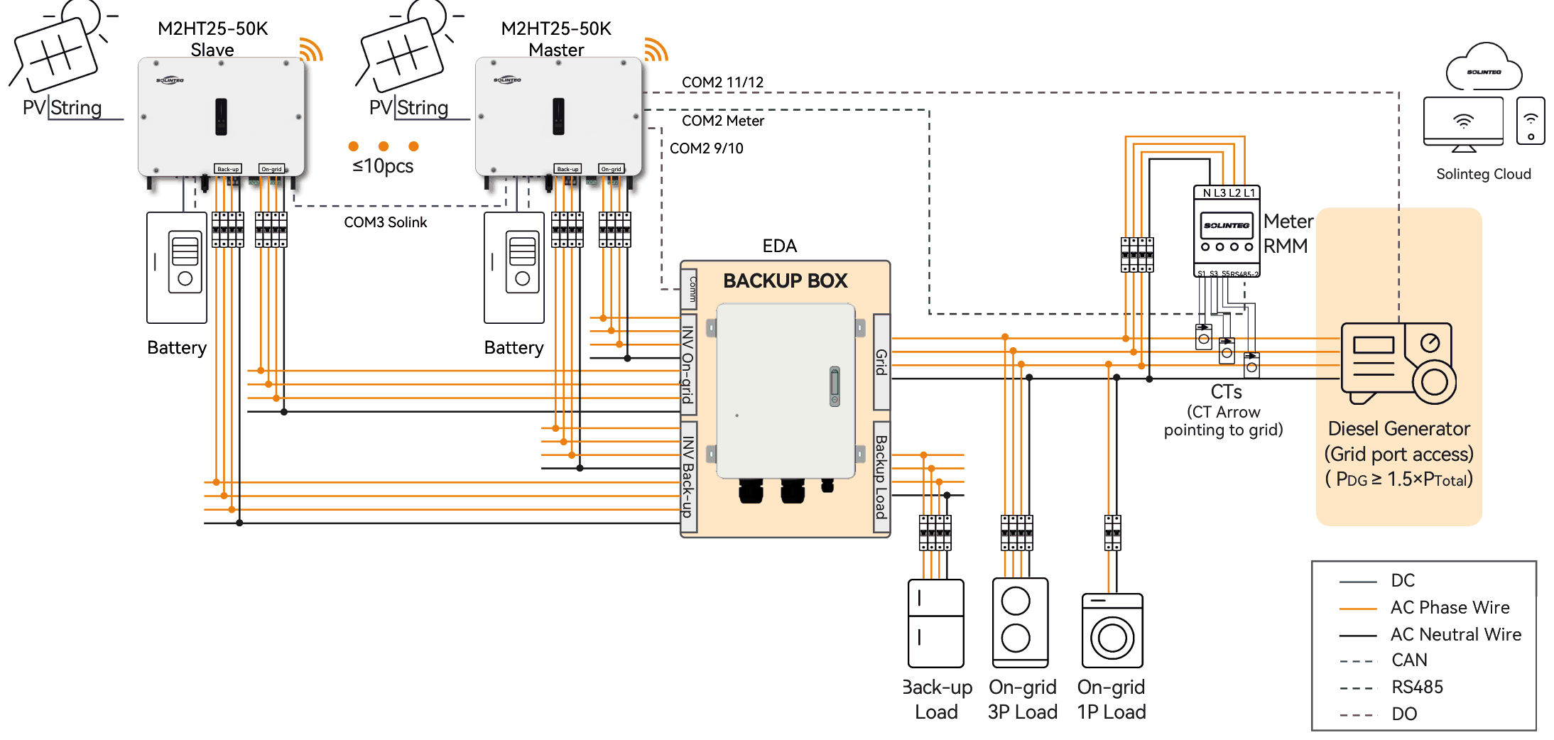
**Figure 3.5** Off-grid parallel with a generator only, connected in place of the grid.
> **Before you design with this solution**
>
> This solution needs the EDA back-up box for reliable operation. All the inverters in parallel must be the same model and power rating. Otherwise the weakest inverter limits the whole system. The generator rating must be at least 1.5 × Ptotal.
### 3.6 Off-Grid Parallel, Scenario 3: Grid and Generator
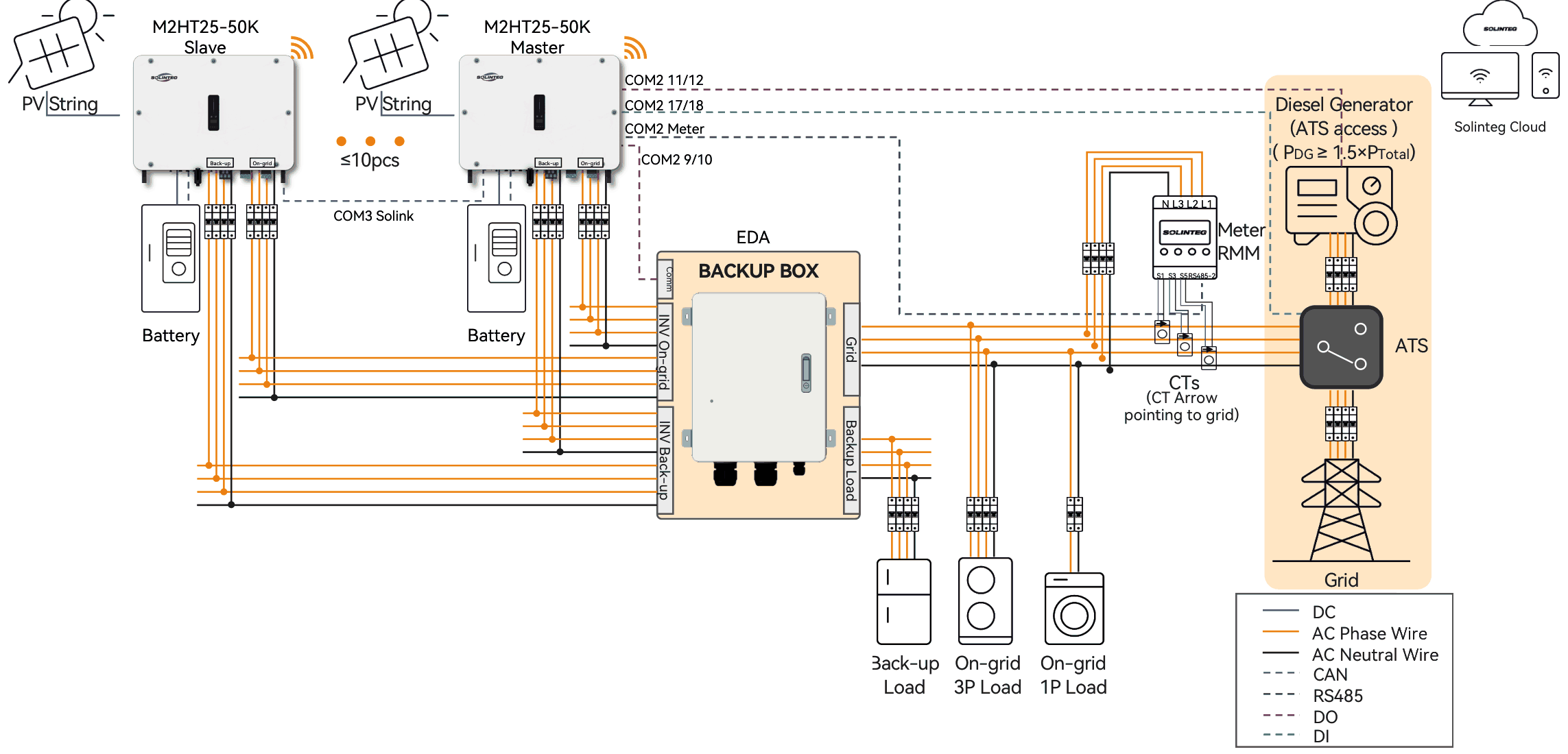
**Figure 3.6** Off-grid parallel with grid and generator, switched by an ATS.
> **Before you design with this solution**
>
> This solution needs the EDA back-up box and an ATS for reliable operation. All the inverters in parallel must be the same model and power rating. Otherwise the weakest inverter limits the whole system. The generator rating must be at least 1.5 × Ptotal.
### 3.7 Off-Grid Parallel, Scenario 4: No Grid, No Generator
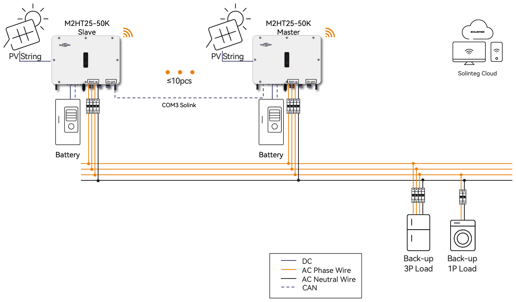
**Figure 3.7** Off-grid parallel with no grid and no generator. The loads are on the back-up side.
> **Before you design with this solution**
>
> All the inverters in parallel must be the same model and power rating. Otherwise the weakest inverter limits the whole system.
### 3.8 On-Grid Parallel, Grid and Generator
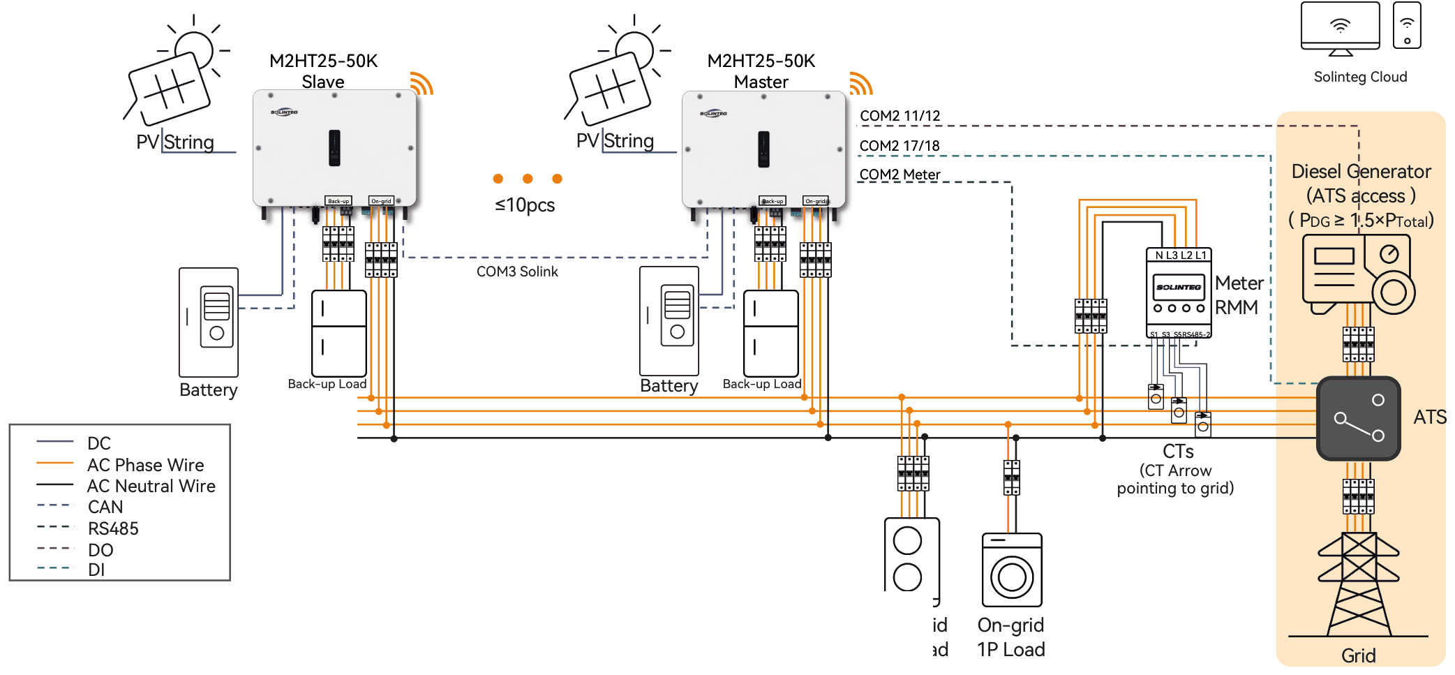
**Figure 3.8** On-grid parallel with grid and generator, switched by an ATS.
> **Before you design with this solution**
>
> All the inverters in parallel must be the same model and power rating. Otherwise the weakest inverter limits the whole system. The generator rating must be at least 1.5 × Ptotal.
### 3.9 EDA Back-Up Box and ATS
The **EDA** is a Solinteg back-up box controller. It switches seamlessly between on-grid and off-grid operation in parallel systems, keeping the system stable and making the hybrid system more reliable and resilient.
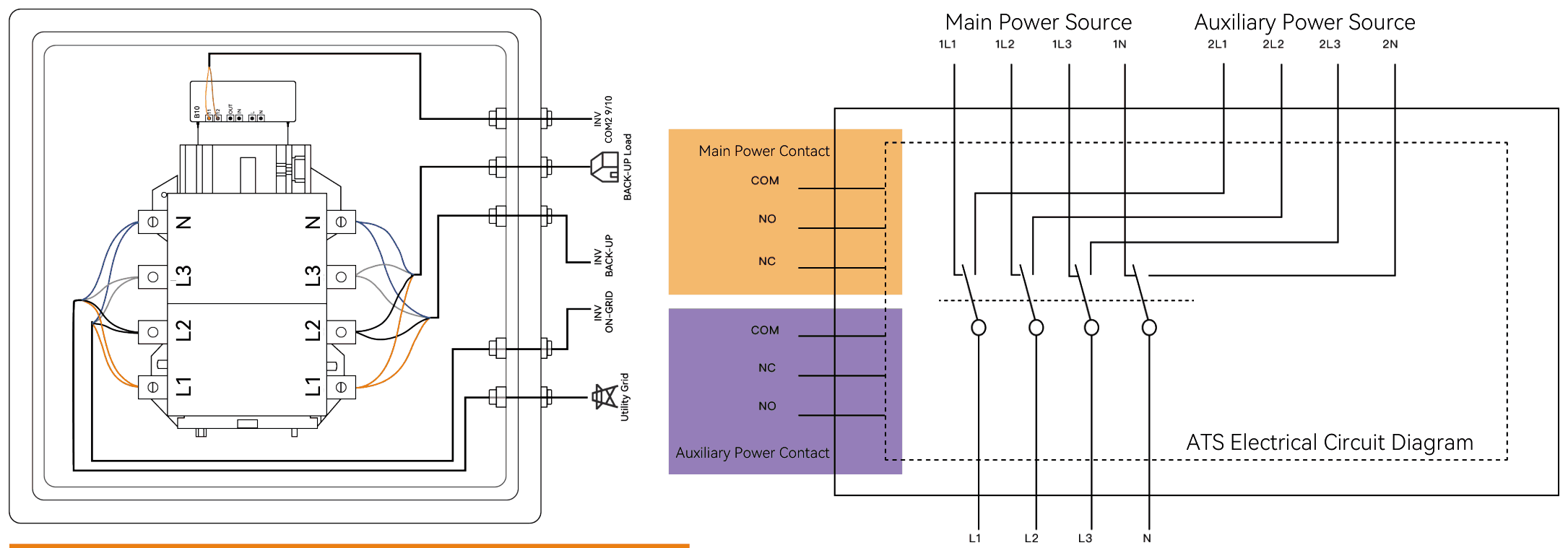
**Figure 3.9** EDA back-up box circuit (left) and ATS circuit (right). The ATS main contact switches the grid (main source) and the auxiliary contact switches the generator (auxiliary source).
| Device | Connects to the inverter (master) at |
|---|---|
| Generator start signal (DO) | COM2 pins 11 and 12 |
| ATS position signal | COM2 pins 17 and 18 |
| EDA back-up box | COM2 pins 9 and 10 |
#### Communication wiring
The inverter reads the ATS signal on COM2 pins 17 and 18 to tell whether the grid or the generator is supplying power:
- **Open** contact: the grid is supplying power.
- **Closed** contact: the generator is supplying power.
Connect EDA pins 11 and 12 to inverter COM2 pins 9 and 10. The order of the two wires does not matter.
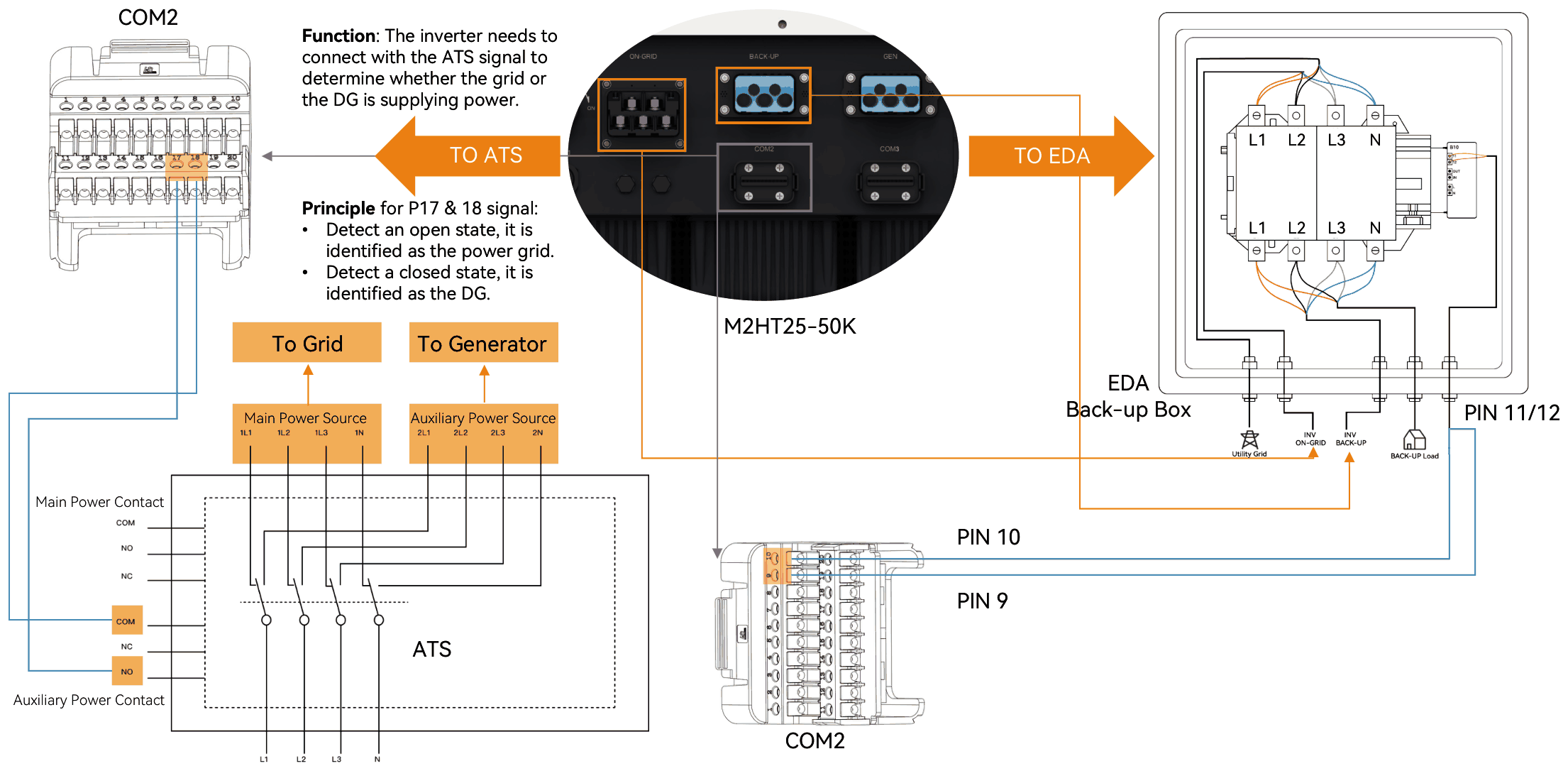
**Figure 3.10** Communication wiring between the inverter COM2 connector, the ATS and the EDA back-up box.
### 3.10 Rules for Off-Grid Paralleling
| Item | Requirement |
|---|---|
| Number of inverters | Up to 10 in off-grid parallel |
| Inverter model | All inverters must be the same model and power rating |
| PV and battery | The PV strings and battery capacity on each inverter must be equal, or close to equal |
| Communication module | Every inverter needs its own communication module (dongle) |
| Smart meter | The RMM smart meter must communicate with the master inverter |
| Item | Requirement |
|---|---|
| EDA | Off-grid parallel needs the EDA back-up box |
| Generator | The generator must support start and stop by a DO (dry-contact) signal |
| ATS | The ATS must have a normally open (NO) auxiliary contact output for the back-up source (generator) |
| Breakers | Every inverter needs its own AC breaker |
| Phase sequence | The phase sequence must match across all the inverters, on both the on-grid side and the back-up side |
| Parallel cables | The parallel communication cables and RJ45 plugs are supplied by Solinteg |
| CAN bus | The CAN communication of every inverter must be working. Turn on the SYNC termination resistor and the parallel CAN termination resistor on the **first and last** inverters only |
| Master position | Only the first or the last inverter in the chain can be the master |
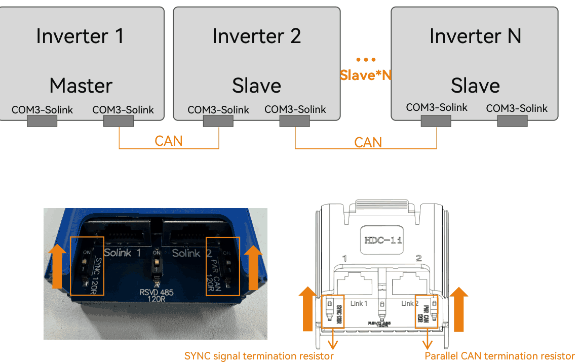
**Figure 3.11** Parallel CAN chain on the COM3 Solink ports, and the SYNC and parallel CAN termination switches.
## 04 App Configuration — Off-grid paralleling, diesel generator
All configuration is done in the Solinteg IntegHub app. Scan a code to install it, or search for **IntegHub** in Google Play or the App Store.
Get the IntegHub app

Android
Google Play

iPhone
App Store
### 4.1 Off-Grid Paralleling
Before you set any parameters:
1. Complete the installation and wiring.
2. Create a plant in Solinteg Cloud or the IntegHub app.
3. Add all the inverters to the plant in the app.
Then work through these five steps:
| Step | What to do |
|---|---|
| 1. Check firmware | Paralleling has no firmware requirement. For automatic generator start, contact AERL. |
| 2. Set inverter roles | Set one inverter as the master and enter the number of inverters in parallel. Set the others as slaves. |
| 3. Set the work mode | Set the work mode on the master. It is synchronised to the slaves automatically. |
| 4. Set the phase sequence | Set the grid phase sequence on the master so the inverters and the grid match. The default is auto-adaptive. |
| 5. Custom switches (optional) | Set only if the site needs it. |
#### Step 1: Check the firmware
1. On the plant page, tap **Device** .
2. On the **Device** page, tap each inverter.
3. Check the **Slave Firmware Version** of every inverter in parallel.
4. Paralleling has no firmware requirement. For automatic generator start, contact AERL.
5. If the firmware needs updating, contact AERL support.
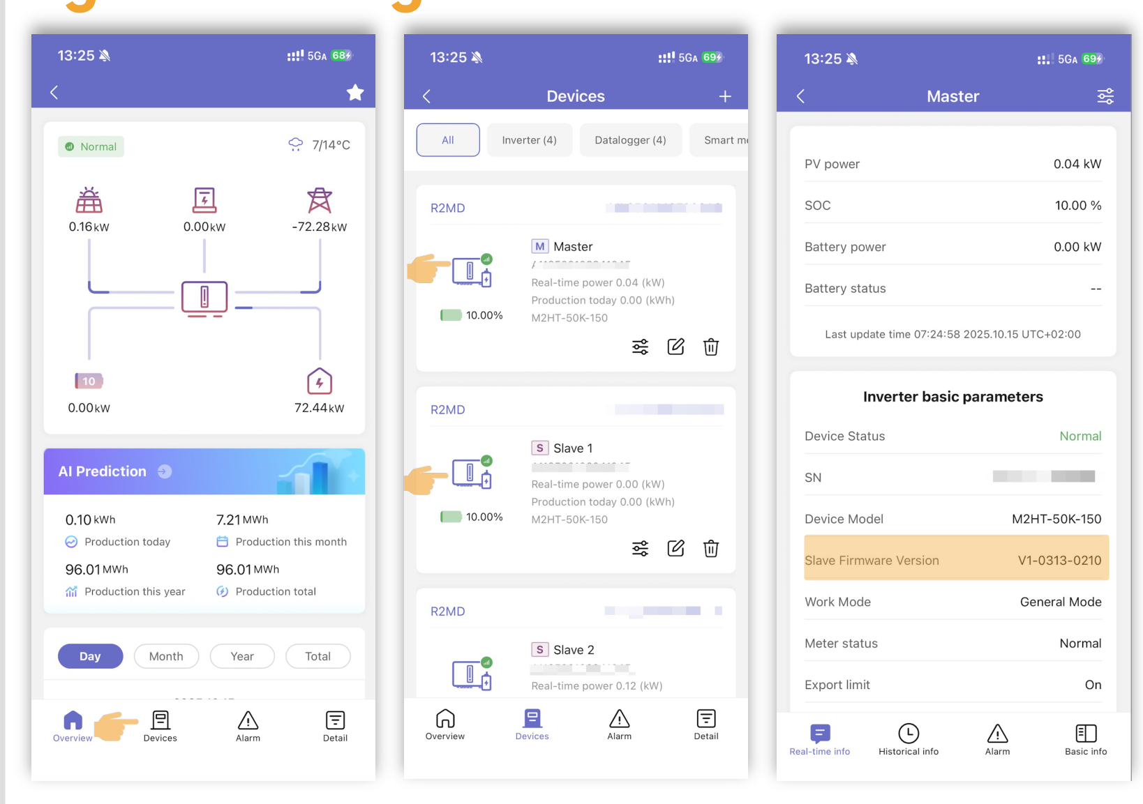
**Figure 4.1** Checking the firmware version in the IntegHub app.
#### Step 2: Set the inverter roles
1. On the **Device** page, tap the settings button of each inverter.
2. On the **Parameter settings** page, tap **Feature parameters** .
3. On the master inverter, set the role to **Master** and enter the number of inverters in parallel.\*
4. On each slave inverter, set the role to **Slave** and enter its inverter address.\*\*
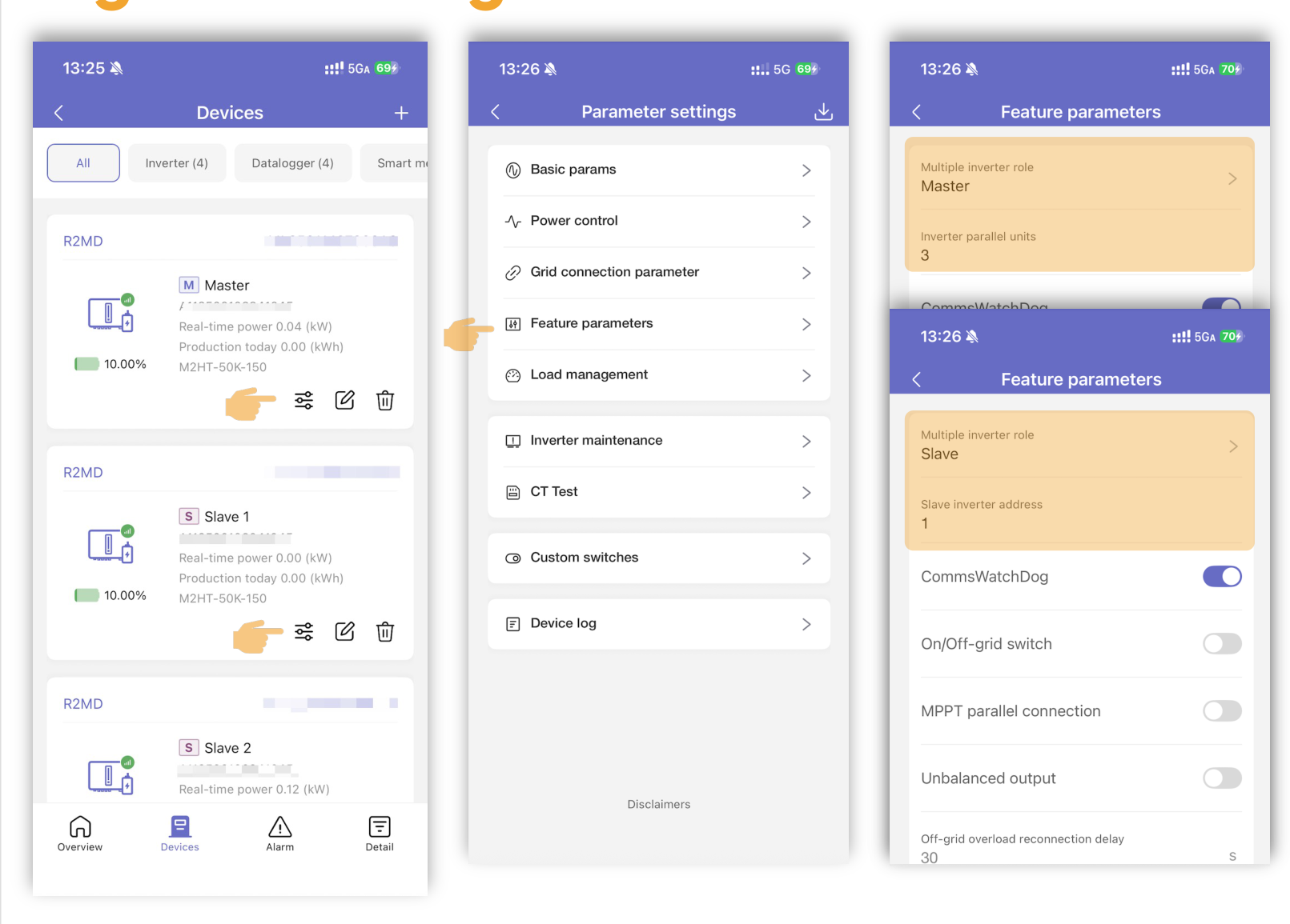
**Figure 4.2** Setting the master and slave roles.
\* The master starts working only when the number of inverters it detects online matches the number entered.
\*\* Slave addresses must start at 1, and be unique and consecutive.
#### Step 3: Set the work mode
1. On the **Device** page, tap the settings button of the **master** inverter.
2. On the **Parameter settings** page, tap **Basic params** .
3. Tap **Work mode** .
4. Select the work mode and tap **Confirm** .
In an off-grid parallel system, set the work mode on the master inverter only.
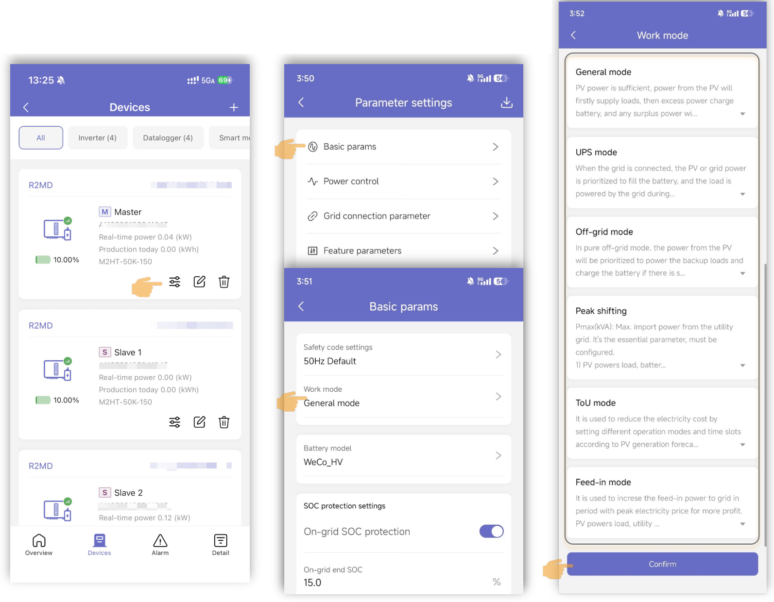
**Figure 4.3** Setting the work mode on the master inverter.
#### Step 4: Set the phase sequence
1. On the **Device** page, tap the settings button of the **master** inverter.
2. On the **Parameter settings** page, tap **Feature parameters** .
3. Tap **Grid phase sequence settings** .
4. Leave the setting at **Auto adaption** (the default and recommended setting), or select **Positive sequence** or **Negative sequence** to suit the site.
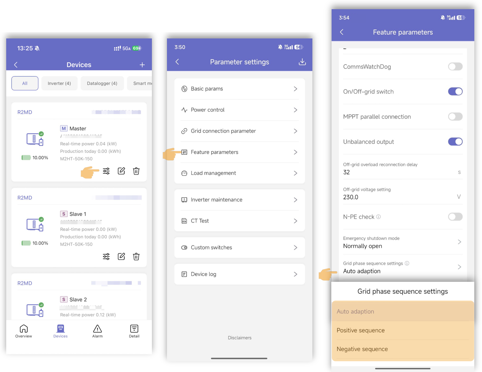
**Figure 4.4** Setting the grid phase sequence.
#### Step 5: Custom switches (optional)
1. On the **Device** page, tap the settings button of the **master** inverter.
2. On the **Parameter settings** page, tap **Custom switches** .
3. Set the switches to suit the site.
> **Warning**
>
> We do not recommend changing the custom switches. If a change is needed, contact AERL support first.
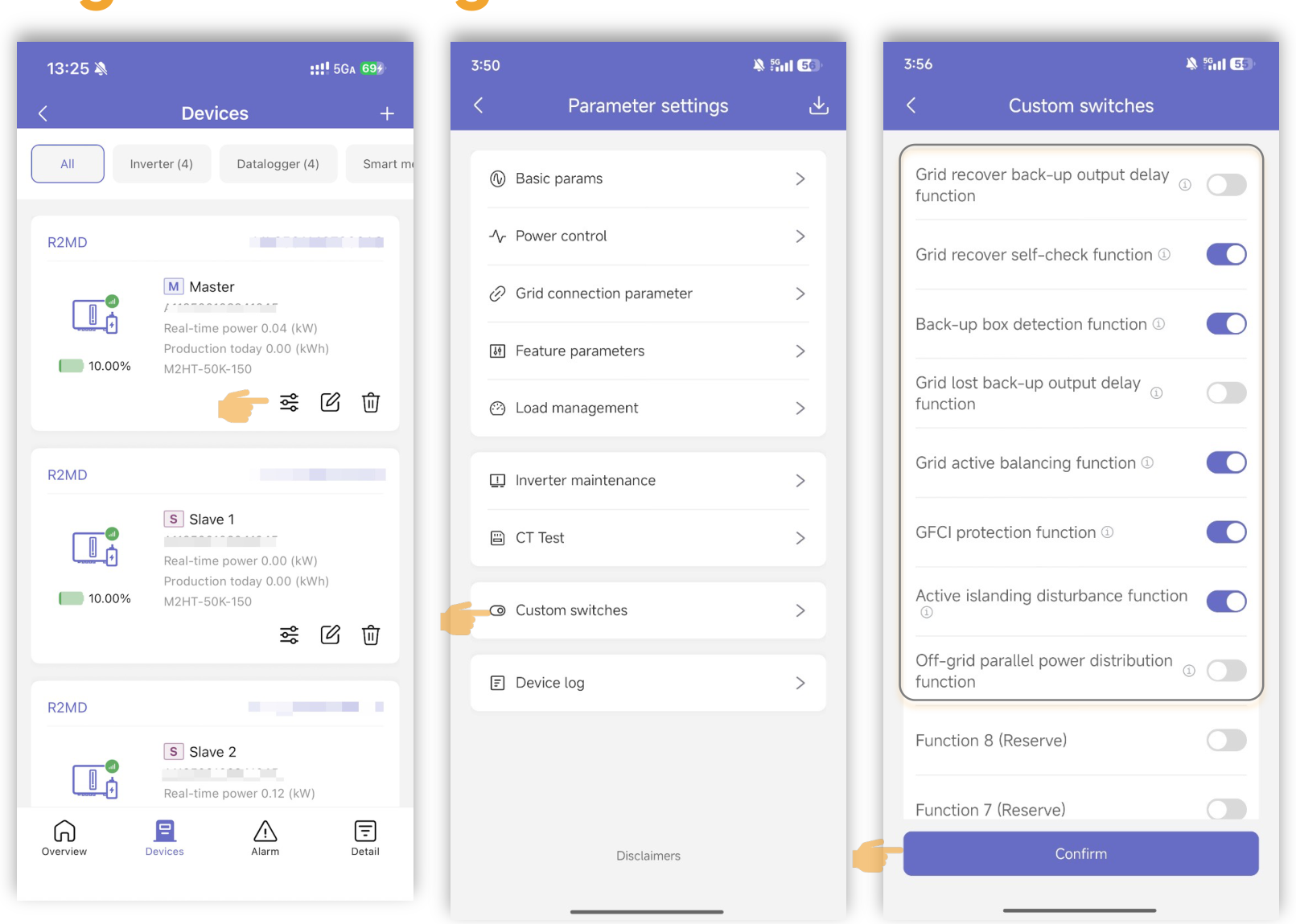
**Figure 4.5** Custom switches.
### 4.2 Diesel Generator
#### Step 1: Add the generator in the IntegHub app
1. You need a hybrid inverter plant in Solinteg Cloud before you can use this function.
2. On the **Devices** page, tap **+** , choose **Third-party devices** and tap the **Diesel generator** icon.
3. Name the generator. Tap **Superior device** and select the serial number of the inverter that the generator connects to.
4. Tap **Unconnected** to choose the access method.
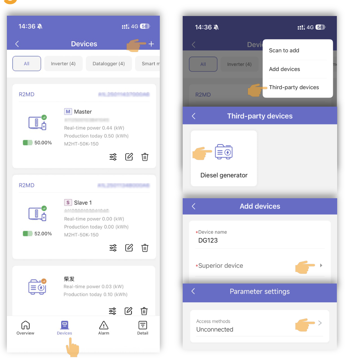
**Figure 4.6** Adding the generator as a third-party device.
#### Step 2: Select the access method
1. Select how the generator is connected (GEN port, ATS or grid port) and tap **Confirm** .
2. Tap the arrow next to **Control mode** and select the control method (section 2.3).
> **Note**
>
> A generator connected at the inverter on-grid (grid) port offers **Manual control** and **SOC control** only. A generator connected at the GEN port or through an ATS also offers **Automatic control**.
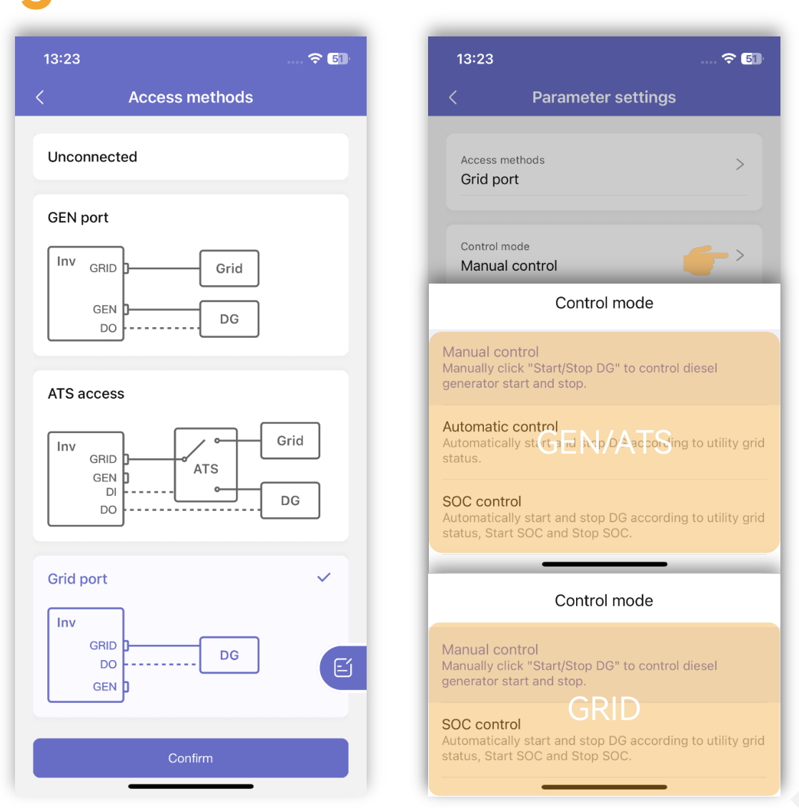
**Figure 4.7** Access methods and control modes. The upper control-mode list applies to the GEN port and ATS; the lower one to the grid port.
#### Step 3: Set the generator parameters
1. Tap the arrow next to **Output mode** and select:
- **Load only** : once started, the generator supplies the loads only
- **Load & Charge battery** : once started, the generator supplies the loads and charges the battery.
2. Set the other generator parameters (such as rated power, maximum power limit, start and stop SOC, start-up delay and stop delay) from the generator rating plate and the site requirements.
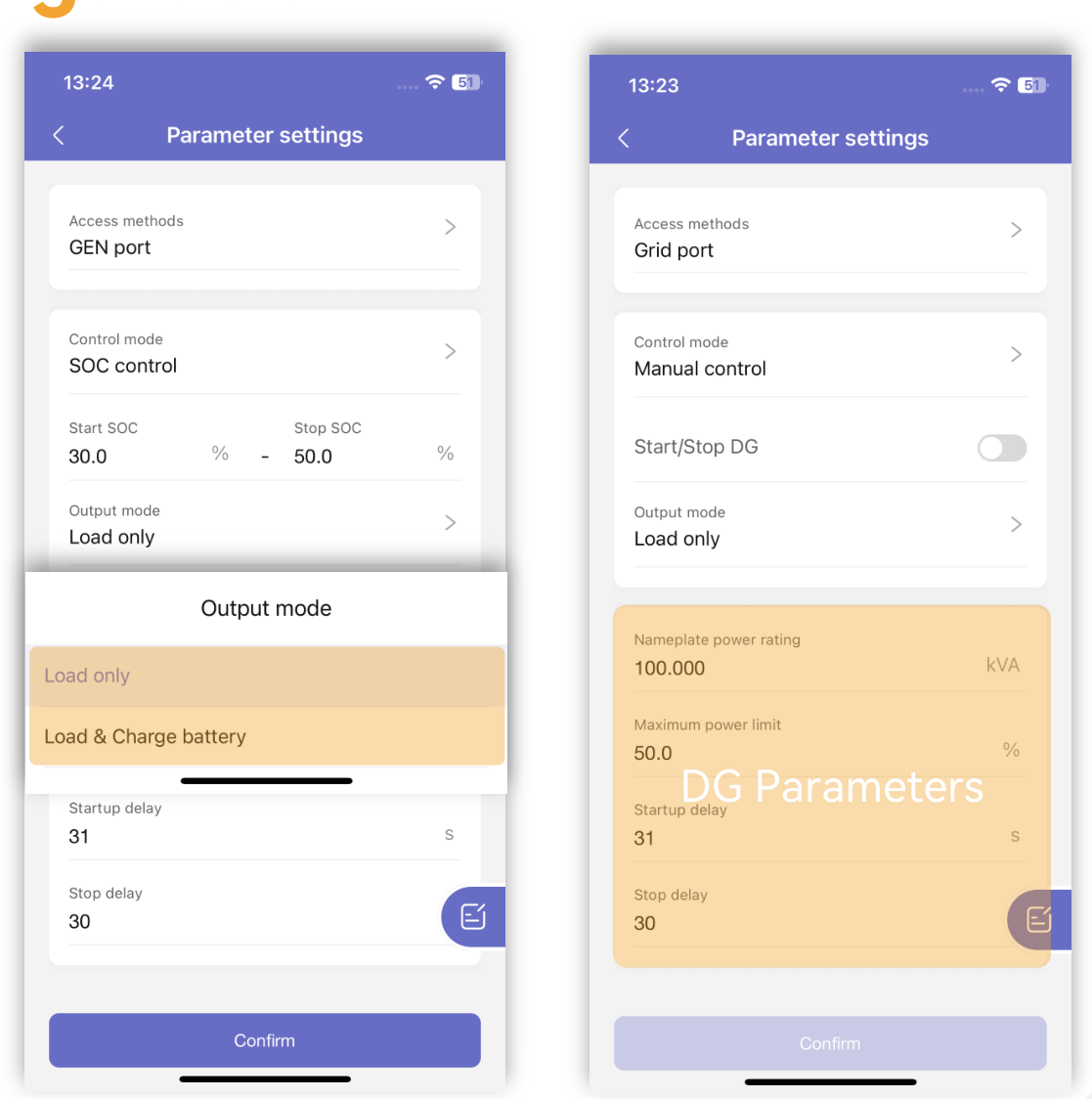
**Figure 4.8** Generator parameters.
## 05 Questions and Answers
#### How do I connect the EDA back-up box to the inverter?
Connect EDA pins 11 and 12 to inverter COM2 pins 9 and 10. The order of the two wires does not matter.
#### How big should the generator be?
At least 1.5 × Ptotal, the total rated power of the inverters. A smaller generator is more likely to give an unstable supply.
#### Can the system avoid exporting power to the generator?
Yes. Because the generator and the inverters never supply the loads at the same time, no power is exported to the generator, provided the system is wired and configured as this guide describes.
#### What happens if an inverter in a parallel system fails?
The parallel system works as a whole. A failed slave inverter is isolated and the rest keep running. If the master fails, the system stops.
#### How do I keep the system running if the master fails and the replacement hasn't arrived?
Make another inverter the master:
1. Choose the slave next to the original master as the new master.
2. Disconnect the CAN cable between the new master and the original master.
3. Move the meter communication cable to the new master.
4. Turn on the termination resistors on the new first and last inverters.
5. Reconfigure the system in the IntegHub app.
#### How do I choose an ATS?
The following is a guide only. Have the final design done by a qualified professional.
1. The ATS current rating should be at least the system's maximum operating current, plus a 10–25% margin.
2. Allow for the generator's starting current and short-circuit capacity.
3. For loads that cannot tolerate an interruption, consider a closed-transition ATS.
4. In three-phase systems, use a 3-pole or 4-pole ATS. Use 4-pole if the neutral must be switched (check the MEN arrangement required by AS/NZS 3000 and AS/NZS 3010).
5. Rate the ATS for the ambient temperature, derating and enclosure rating (IP) of the installation.
#### How does M2HT paralleling differ from the earlier MHT 25–50 kW?
| | MHT 25–50 kW | M2HT 25–50 kW |
|---|---|---|
| Inverters in parallel | Up to 4 off-grid; up to 10 on-grid | Up to 10 off-grid; up to 10 on-grid |
| Firmware | ARM 05 or later and DSP 05 or later | No firmware requirement for paralleling |
| Work modes | 7 | 6 (no economic mode) |
| Parallel connection | COM2 pins 17 and 18, twisted pair | COM3 Solink ports (RJ45) |
| Termination (DIP switches) | Turn on PAR CAN 120R on the first and last inverters | Turn on SYNC 120R and PAR CAN 120R on the first and last inverters |
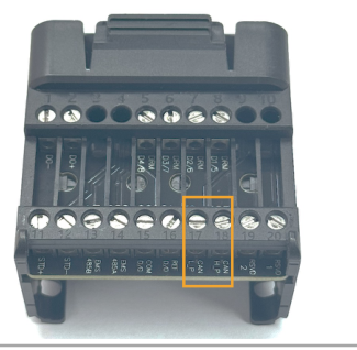
**Figure 5.1** MHT: parallel connection on COM2 pins 17 and 18.
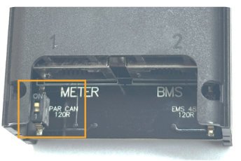
**Figure 5.2** MHT: PAR CAN 120R switch.
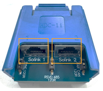
**Figure 5.3** M2HT: Solink 1 and Solink 2 ports on COM3.
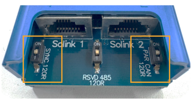
**Figure 5.4** M2HT: SYNC 120R and PAR CAN 120R switches.
## 06 Technical Support
Contact AERL for help with system design, installation, commissioning, firmware, warranty and spare parts for Solinteg inverters, EDA back-up boxes and batteries in Australia.
#### AERL technical support
- **Phone:** 1800 950 865
- **Email:** support@aerl.com.au
- **Web:** aerl.com.au
- **Address:** AERL, 1/75 Bluestone Circuit, Seventeen Mile Rocks QLD 4073, Australia
When you contact AERL, have the following ready:
- the solution you are using (sections 3.1–3.8) and a single-line diagram of the site
- the model, serial number and firmware versions of every inverter, and which one is the master
- the generator make, model and rating, and the ATS make and model, if fitted
- any alarm or fault codes, and when they occurred
- screenshots of the parallel and generator settings in the IntegHub app.
 
Manufactured by **Solinteg** Supplied and supported in Australia by **AERL**
Australian Energy Research Laboratories
### Address
1/75 Bluestone Circuit Seventeen Mile Rocks QLD 4073 Australia
### Contact
[sales@aerl.com.au](mailto:sales@aerl.com.au) [support@aerl.com.au](mailto:support@aerl.com.au)
aerl.com.au Phone **1800 950 865**
Australian edition Solinteg M2HT 25–50 kW · Paralleling & Generator Guide **Rev 1.0.2**