

Solinteg M2HT 25–50 kW Hybrid Inverter
Three-Phase High-Voltage Hybrid Inverter
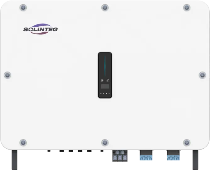
M2HT-25K · 29.9K · 30K · 40K · 50K
Quick Start GuideRev 1.0.2, 9 Nov 2026
Three-Phase High-Voltage Hybrid Inverter
This guide covers the essential steps to install, connect and start up the Solinteg M2HT 25–50 kW hybrid inverter. It does not replace the Solinteg M2HT 25–50 kW User Manual. Read the manual's safety instructions (§1) before you start, and use it for any step you are unsure of. References such as §5.4 point to the user manual.

Install in accordance with AS/NZS 3000, AS/NZS 4777.1, AS/NZS 4777.2, AS/NZS 5033 and AS/NZS 5139, and the requirements of the local network service provider. Connect to the grid only with network approval. Never work on live equipment: isolate every supply first. Connect the protective earth before anything else.
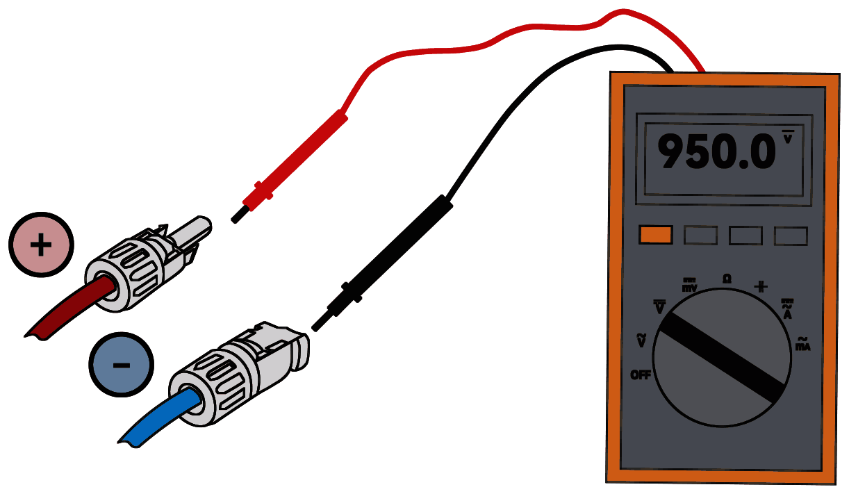
The PV array produces dangerous DC voltage in sunlight. PV strings must not exceed 950 V (above 1000 V the inverter is damaged). The battery must not exceed 840 V. Wait 10 minutes after isolating before touching internal parts.

For a parallel system, see §5.10 and contact AERL when designing it.
| Item | Value | Manual |
|---|---|---|
| Inverter size (W × H × D) | 919 × 739 × 305 mm, 89 kg, IP66 | §11 |
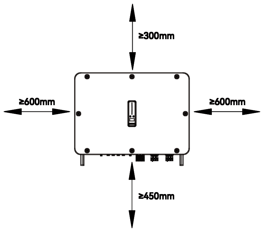
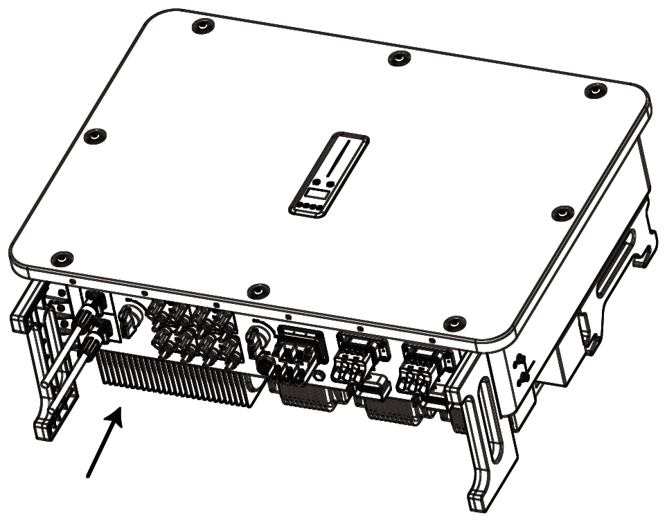
| Clearances | 300 mm above, 450 mm below, 600 mm each side; 600 mm between inverters | §4.1 |
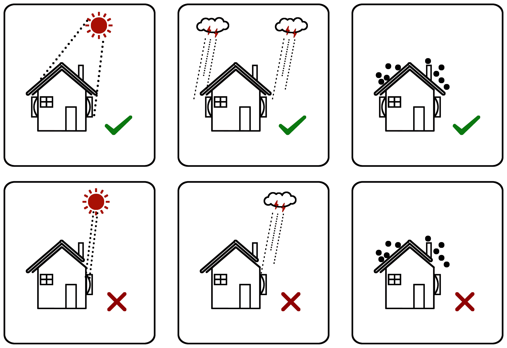
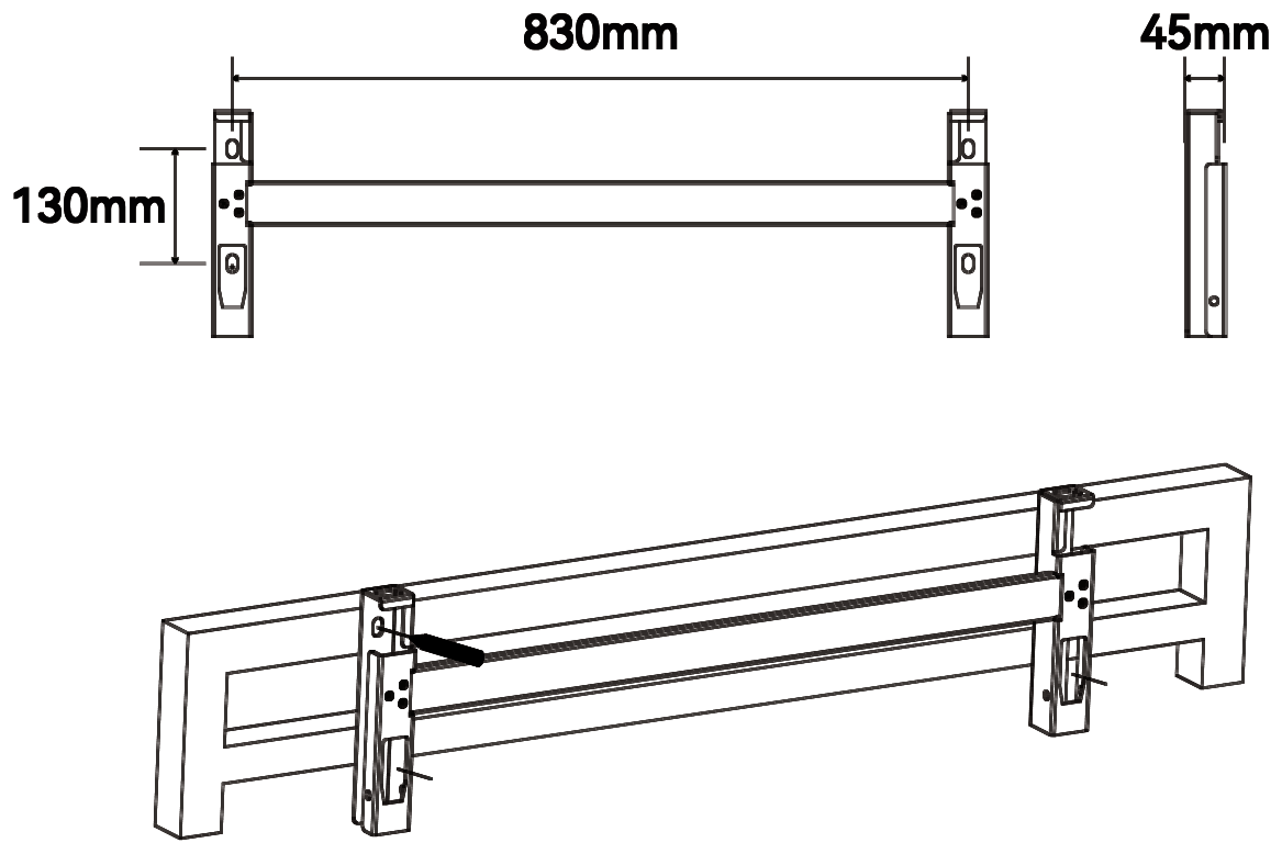
| Mounting | Vertical only, on a wall that can carry the weight; out of direct sun and rain | §4.1 |
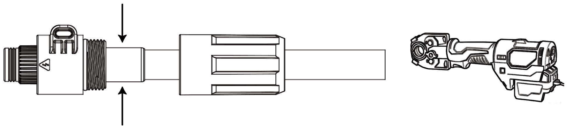
| On-grid AC cable | 5-core, 16–50 mm², 20–37 mm OD; strip sheath 95–100 mm, cores 20–25 mm | §5.4 |
| On-grid connector torques | Lugs 3.8 N·m; connector nut 10 N·m | §5.4 |
| Back-up / generator AC cable | 5-core, 10–25 mm² flexible or 10–35 mm² rigid; strip cores 15 mm; screws 5 N·m, nut 10 N·m | §5.4 |
| PV cable | 4 or 6 mm², 5.9–8.8 mm OD; strip 7 mm | §5.5 |
| PV voltage | 950 V operating max.; 1000 V absolute | §5.5 |
| Battery cable | 50 mm², 13 mm OD; strip 16.5 mm | §5.6 |
| Battery voltage | 150–840 V; fuses in both conductors | §5.6 |
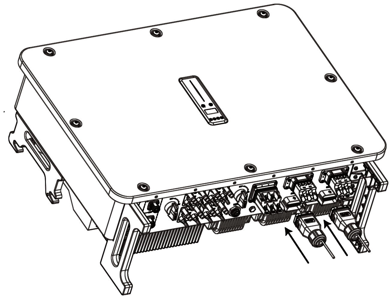
| Communication terminals | 0.5–1.5 mm²; strip sheath 55 mm, cores 8 mm; 1.2 N·m | §5.9 |
| Breakers (on-grid / back-up) | 25K: 100 / 63 A · 29.9K and 30K: 125 / 80 A · 40K: 160 / 100 A · 50K: 160 / 125 A | §5.2 |
| RCDs | 30 mA type A on the load circuits | §5.2 |
| Operating temperature | −30 to 60 °C (derating above 45 °C) | §4.1 |
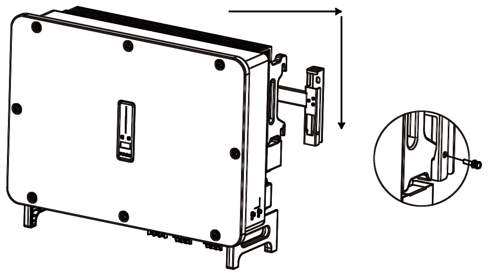
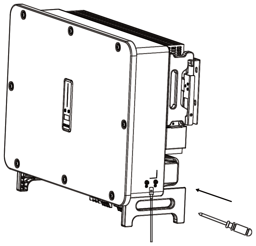
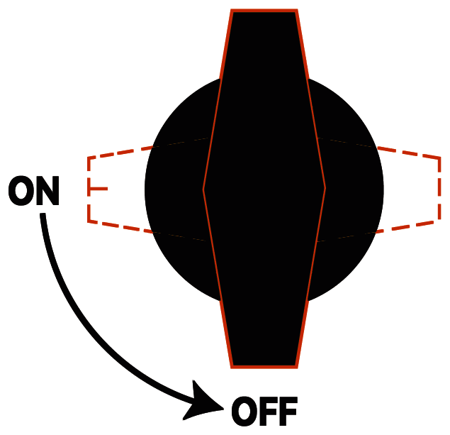
Switch off all AC breakers, the battery breaker and the inverter DC switch. Check every cable is dead. Do not switch on any breaker until all connections are complete.
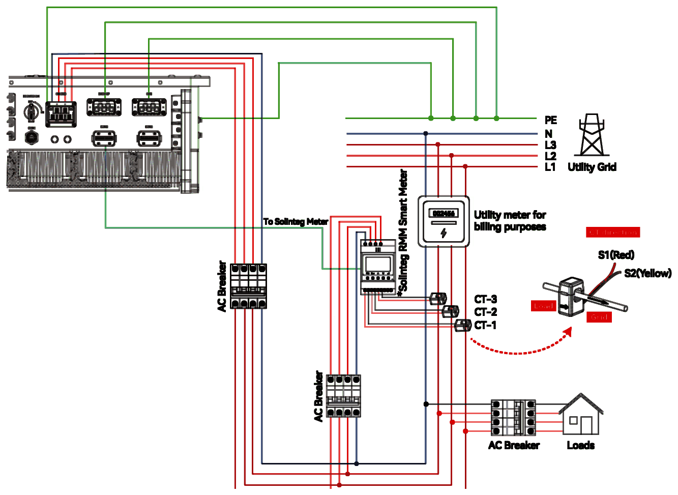
In Australia the neutral must not be switched, and the grid-side and back-up neutrals must be connected together (AS/NZS 3000). Fit a separate breaker on each AC output; never connect loads directly to the inverter. Do not confuse the back-up and generator connectors (§5.2, §5.4).
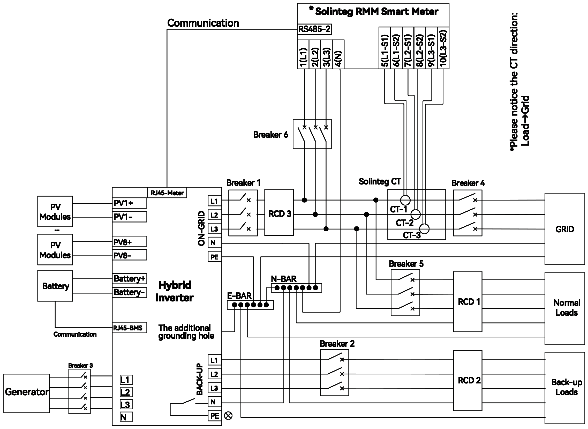
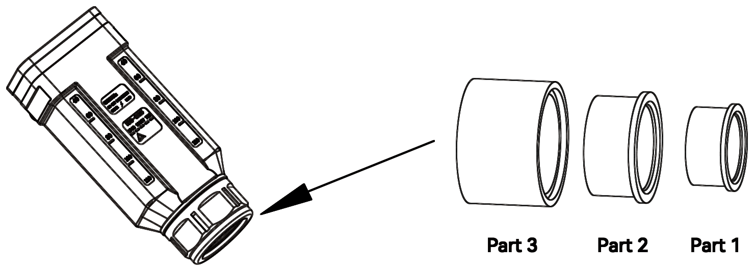
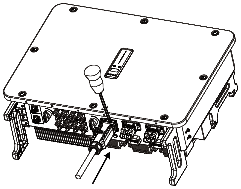
Fit an external DC isolator to AS 60947.3:2018 and AS/NZS IEC 60947.1:2020 where required.
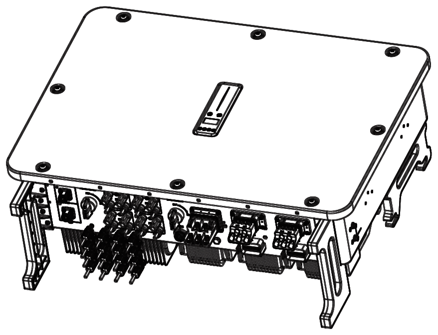
| Step | Action |
|---|---|
| 1 | Switch on the AC breaker |
| 2 | Switch on the battery, and power up the battery pack if required |
| 3 | Turn on the DC switch, then wait 5 minutes |
| 4 | Set the safety code to the AS/NZS 4777.2 region your network requires, and the battery ID to the battery fitted |
| 5 | The inverter connects to the grid when conditions are met (this can take several minutes) |
| 6 | Check the indicators, then run the CT auto test and an SOC reset from the app |
| Indicator | Running normally |
|---|---|
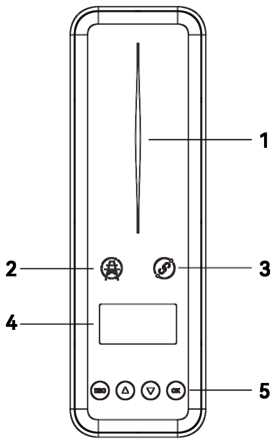
| Power (blue) | Breathing |
| Grid | On steady (on-grid) |
| Communication | Green |
| Communication orange / red | No meter / no BMS communication |
| Power red | Alarm: check the display |
Scan a code to install the free Solinteg IntegHub app, or search for IntegHub in Google Play or the App Store.


The safety code, protection and power quality settings are password protected. Contact AERL support for the password (§7.6).
| Message | Meaning | First check |
|---|---|---|
| BMS Comm Fault | No BMS communication | Battery ID setting; cable in BMS 1 (not BMS 2); battery status |
| Meter Comm Fault | No meter communication | METER cable and connections; compatible meter model |
| PV Over Voltage | PV voltage above the limit | Reduce modules per string so Voc stays below the maximum |
| ISO Over Limitation | DC insulation resistance too low | PV modules, cables and connectors for water or damage; insulation ≥ 500 kΩ |
| Grid Voltage Fault | Grid voltage outside the safety code limits | Safety code; AC wiring; voltage rise from undersized AC cable |
| Backup Load Fault | Back-up load above capacity | Reduce the back-up load; check battery capacity |
| Over Temperature | Inverter too hot | Ventilation and clearances; let it cool, then restart |
The full list of status codes and faults is in §8 of the user manual.

1800 950 865 · [email protected] · aerl.com.au
Have ready: the inverter model and serial number, the installation date, the fault message and when it occurred, and photos of the installation.
Australian Energy Research Laboratories
1/75 Bluestone Circuit
Seventeen Mile Rocks QLD 4073
Australia