

Solinteg M2HT 25–50 kW Hybrid Inverter
Three-Phase High-Voltage Hybrid Inverter
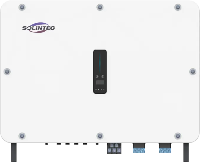
M2HT-25K · 29.9K · 30K · 40K · 50K
User ManualRev 1.0.2, 9 Nov 2026
Three-Phase High-Voltage Hybrid Inverter
This manual covers the installation, electrical connection, commissioning, operation, maintenance and troubleshooting of the Solinteg M2HT 25–50 kW three-phase high-voltage hybrid inverter (the "inverter" in this manual). It applies to these models:
| Model | Rated power |
|---|---|
| M2HT-25K-150 | 25 kW |
| M2HT-29.9K-150 | 29.9 kW |
| M2HT-30K-150 | 30 kW |
| M2HT-40K-150 | 40 kW |
| M2HT-50K-150 | 50 kW |
This manual is for licensed electrical workers who install and maintain the inverter, and for system owners. Anyone installing, maintaining or troubleshooting the inverter must:
Only people who meet all of these requirements may install, maintain or troubleshoot the inverter.

Indicates a hazard with a high level of risk that, if not avoided, will result in death or serious injury.
Indicates a hazard with a medium level of risk that, if not avoided, could result in death or serious injury.

Indicates a hazard with a low level of risk that, if not avoided, could result in minor or moderate injury, or damage to equipment.

Extra information to help you use the equipment. Notes are not safety warnings.
This is AERL's Australian edition of the Solinteg M2HT 25–50K user manual. AERL has rewritten the text for clarity and adapted it for Australia. The product specifications are Solinteg's. Illustrations are for reference only and may differ from your product. Download the latest edition from aerl.com.au.
The warranty for this inverter is set out in the Solinteg M2HT Warranty, available from AERL.
Read this manual before you transport, store, install, operate or maintain the inverter, and follow its safety instructions and the labels on the equipment. The warranty does not cover damage caused by:
The M2HT 25–50 kW is a three-phase hybrid (storage) inverter. It connects a PV array, a high-voltage lithium battery, loads and the grid, and manages the power flow between them.
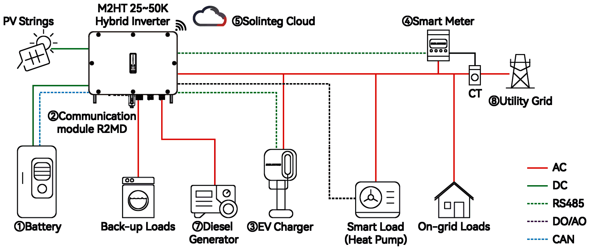
| Equipment | Requirement |
|---|---|
| Battery | A high-voltage lithium iron phosphate (LFP) battery with BMS, from Solinteg's compatibility list. See the AERL Compatibility Guide (aerl.com.au). |
| Communication module | The Solinteg R2MD module, supplied with the inverter. |
| EV charger | A Solinteg ECA-series charger, if the inverter is to control it. |
| Smart meter | The Solinteg RMM smart meter, supplied with the inverter. |
| Monitoring | Solinteg Cloud and the IntegHub app. |
| Diesel generator | Optional. See the Solinteg M2HT 25–50 kW Paralleling & Generator Guide. |
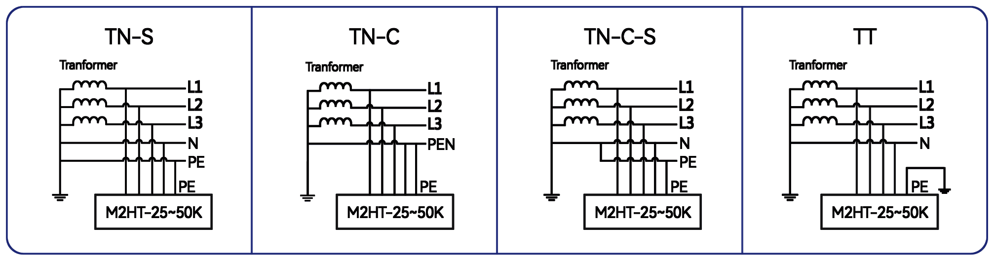
The inverter suits TN-S, TN-C, TN-C-S and TT earthing systems. On a TT system, the N-to-PE voltage should be below 30 V. In Australia, the MEN (TN-C-S) system applies.
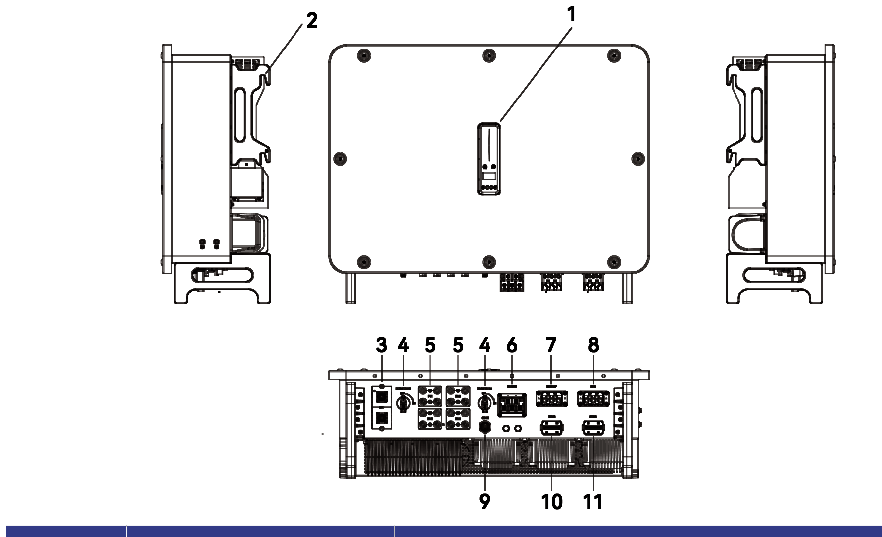
| No. | Name | Description |
|---|---|---|
| 1 | Indicators, OLED display and button | Show the inverter's operating information and status |
| 2 | Hanger | Hangs the inverter on its mounting bracket |
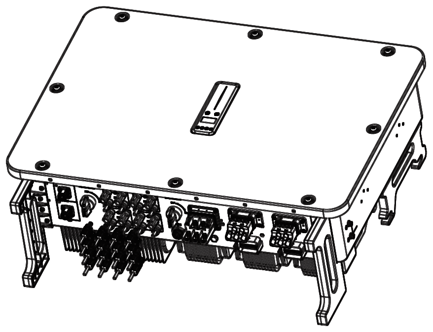
| 3 | Battery input terminals | Battery connectors |
| 4 | DC switches | Isolate the PV input |
| 5 | DC input terminals | PV connectors |
| 6 | On-grid output terminal | On-grid AC cable |
| 7 | Back-up output terminal | Back-up AC cable |
| 8 | Generator input terminal | Diesel generator AC cable |
| No. | Name | Description |
|---|---|---|
| 9 | COM1 port | Communication module (R2MD) |
| 10 | COM2 port | Multi-function communication connector |
| 11 | COM3 port | Multi-function communication connector (blue) |
| Symbol | Meaning |
|---|---|
| TÜV, CE and UKCA marks | Certification marks |
| RCM mark | Complies with Australian and New Zealand electrical safety and EMC requirements |
| Crossed-out wheelie bin | Do not dispose of in general waste. Recycle as e-waste |
| Book | Read the instructions before installation |
| Warning triangle | Danger |
| Hot surface | Do not touch: hot during operation |
| 10 min | Do not touch internal parts for 10 minutes after disconnecting the grid, battery and PV |
| Lightning bolt | Risk of electric shock |
| Earth | Protective earth terminal |
The inverter has six operation modes: General, Peak Shifting, Feed-in, Backup, Time of Use (ToU) and Off-grid. Set the mode on the inverter display, in Solinteg Cloud or in the IntegHub app.
In General, Peak Shifting, Feed-in, Backup and ToU modes, if the grid fails the inverter switches automatically to off-grid operation and supplies the back-up loads, provided the On/Off-grid switch setting is on. The operation mode itself does not change.
When there is enough PV, it supplies the loads first, then charges the battery, then exports to the grid (PV → loads → battery → grid). You can set export to 0 W where the network does not allow export. When PV is not enough, the battery discharges to the loads, and the grid makes up any shortfall or takes over when the battery reaches its end SOC.
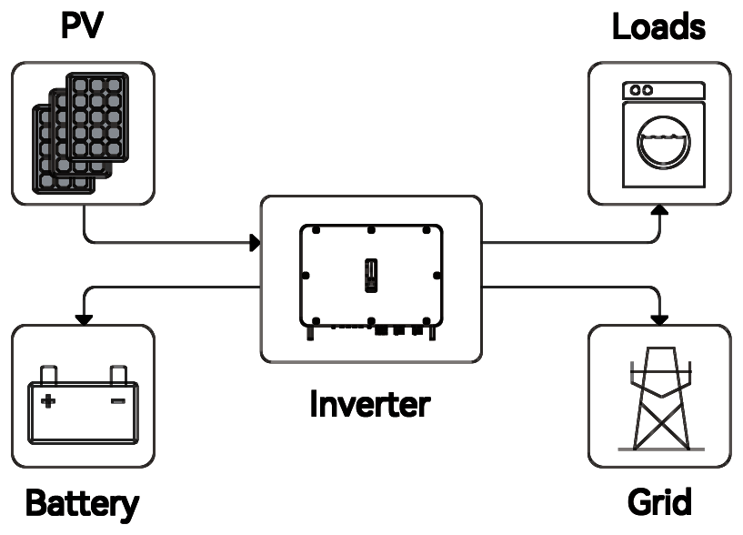
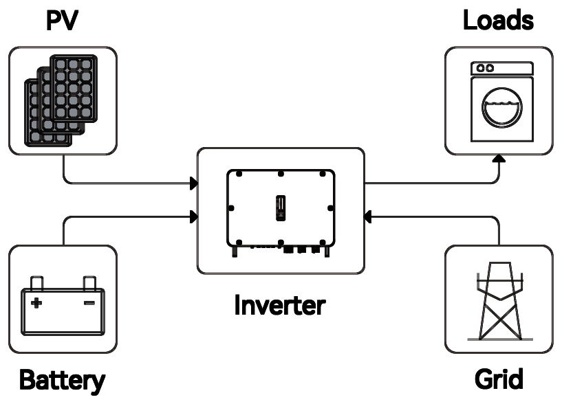
EXPmax (kVA) is the maximum power you want to import from the grid. PV supplies the loads, then the battery, then the grid. The loads are supplied from PV first, then from the grid up to EXPmax, then from the battery. Surplus PV or grid power charges the battery.
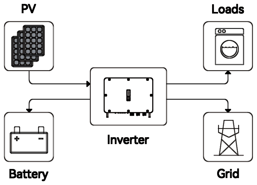
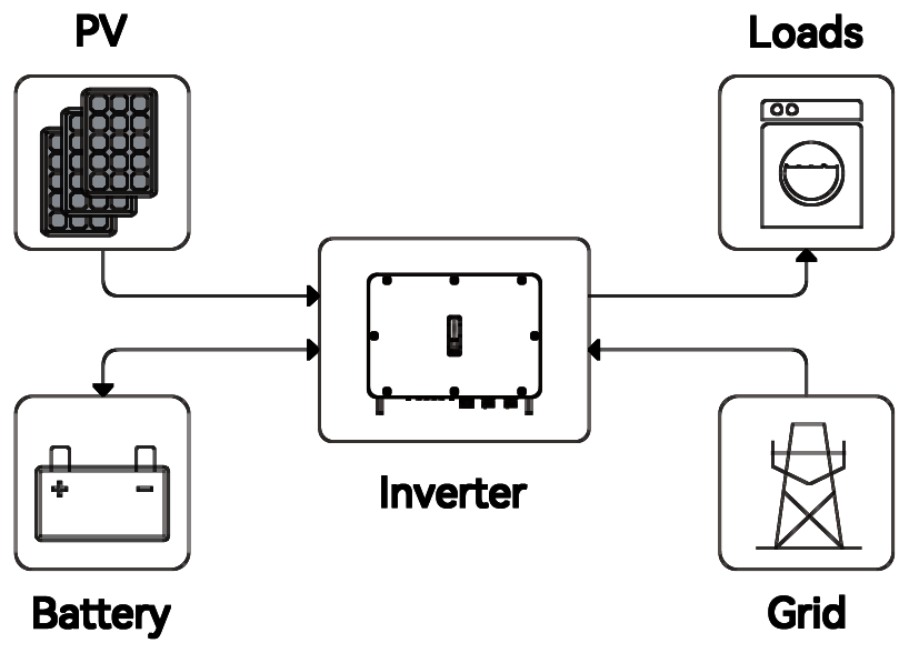
For Peak Shifting to work, the load above EXPmax must be within the inverter's maximum output power. Otherwise the inverter supplies only its maximum allowed power.
When there is enough PV, it supplies the loads first, then exports to the grid, then charges the battery (PV → loads → grid → battery). When PV is not enough, PV and the battery supply the loads together, and the grid makes up any shortfall.
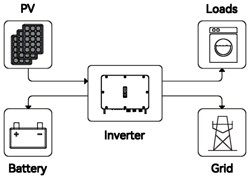
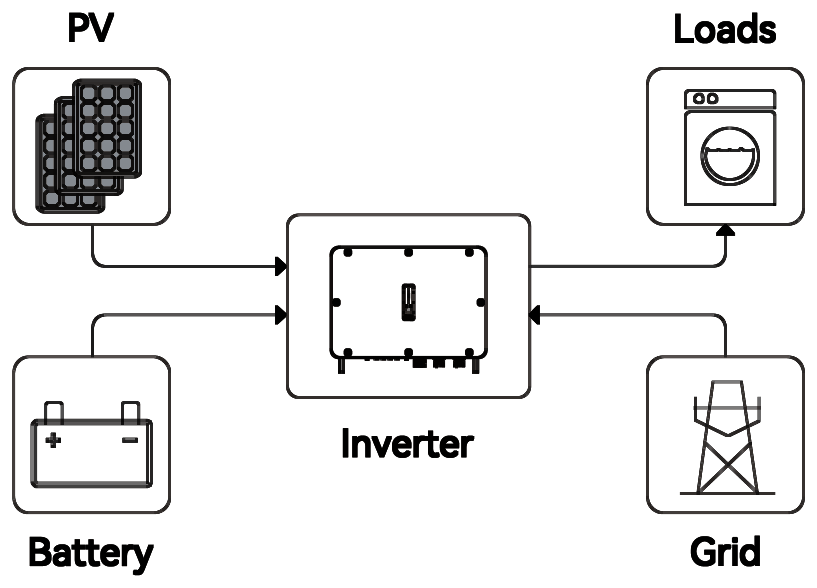
The inverter charges the battery from PV and the grid until it is full, and any surplus supplies the loads. The battery does not discharge while the grid is available. When the grid fails, PV and the battery supply the back-up loads.
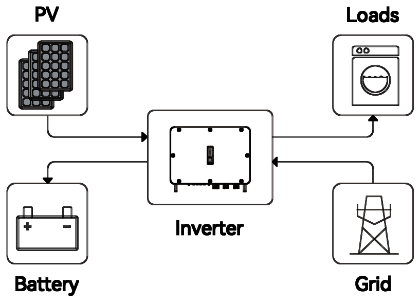
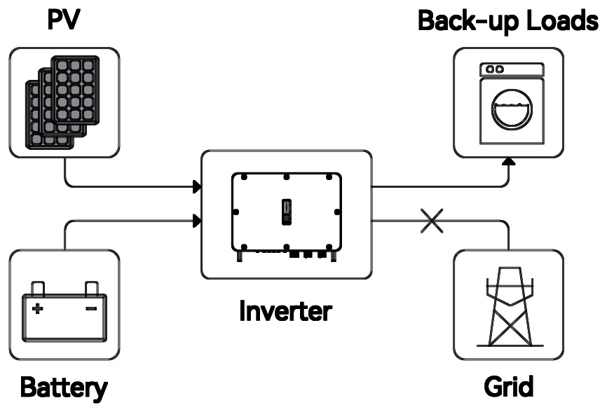
You set a different mode for each time period. The modes available in a ToU period are General, Battery Charge, PV Charging, Peak Shifting, Feed-in and Battery Discharge. General, Peak Shifting and Feed-in work as described above.
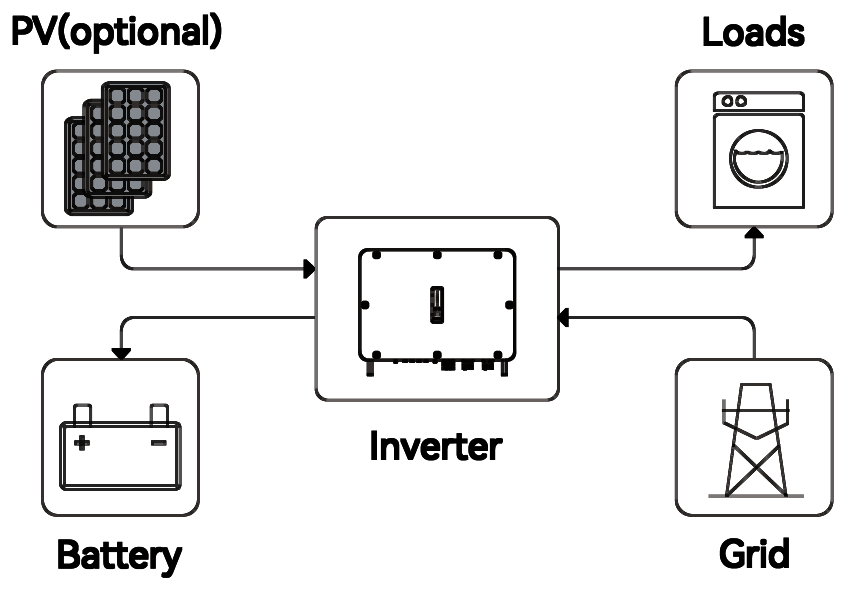
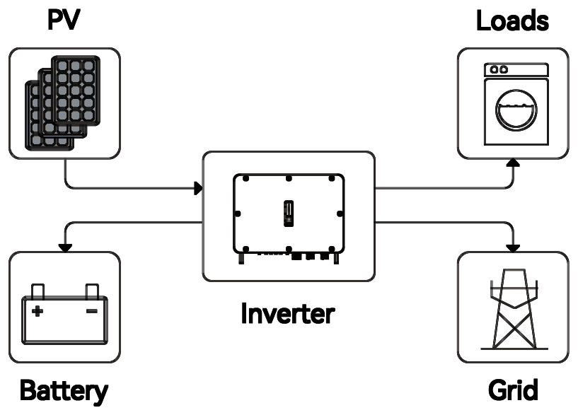
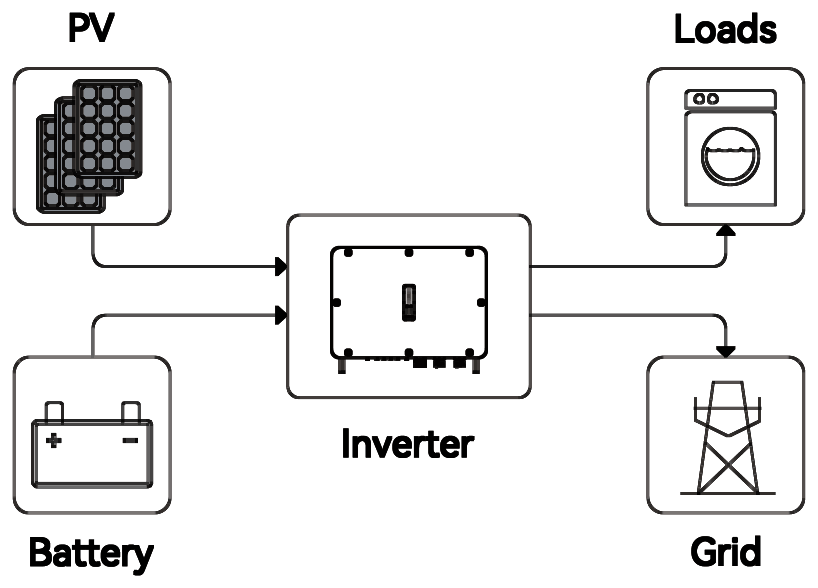
With no grid, PV supplies the back-up loads first and charges the battery with any surplus. When PV is not enough, the battery discharges to supply the back-up loads together with PV.
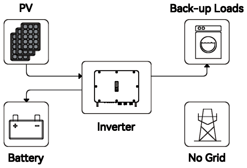
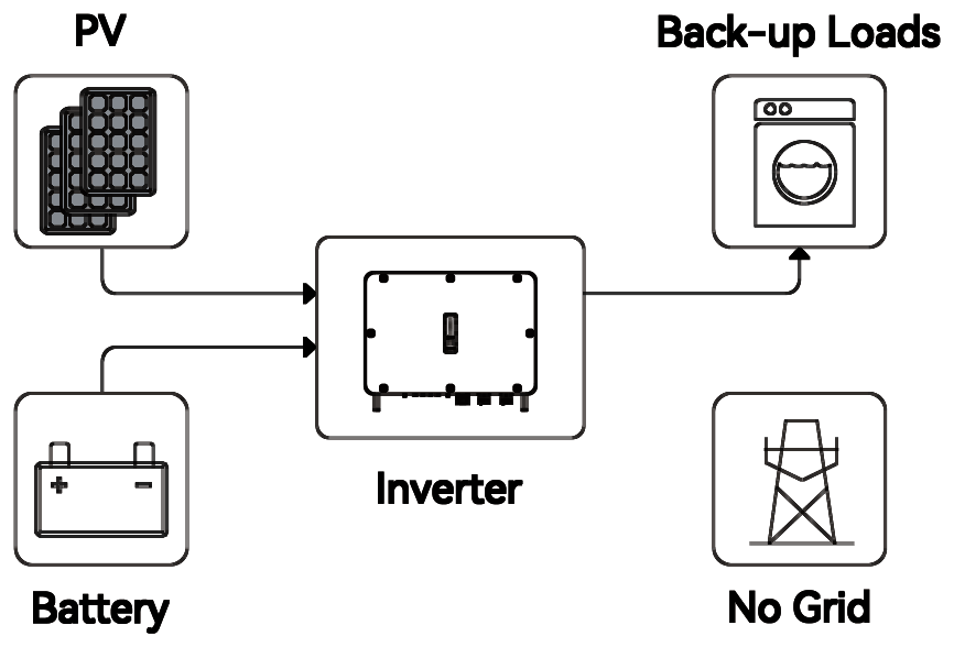
The system is not suitable for life-support or other medical equipment. A power outage could be life-threatening.
Do not use the back-up supply for equipment or precision instruments that may fail or be damaged by an outage or power fluctuation. Before inspecting or maintaining the back-up circuit, switch off the back-up and on-grid breakers to isolate the loads and the inverter completely.
The inverter is not a conventional UPS. Never connect the back-up output to the grid. The back-up function will not work. In off-grid operation, the inverter stops the back-up supply when there is no energy available from PV or the battery.
A single inverter normally switches between on-grid and off-grid within 10 ms, but external factors can stop it switching. When using the back-up function:
| Load type | Examples | Why |
|---|---|---|
| High inrush current (motors) | Pumps, chainsaws | The starting current may exceed the inverter's peak capability, even if the running power is within its rating |
| Fluctuating power | Washing machines, blenders, rice cookers, ovens | The load power changes repeatedly |
| High harmonic current | Induction cooktops, hair dryers, heat guns, hammer drills | Non-sinusoidal current can distort the voltage |
The back-up / off-grid peak output is 1.5 × rated output power for 10 seconds on all models. If the overload protection operates, the inverter restarts. Repeated overloads lengthen the restart time, up to 2 minutes. Reduce the back-up load or remove loads with very high starting current.
The inverter reduces its output to protect itself, or as the grid requires, in conditions including:
The inverter is tested and inspected before shipping, but can still be damaged in transit. Inspect it on delivery. If anything is damaged or missing, contact AERL or the carrier and send photos.
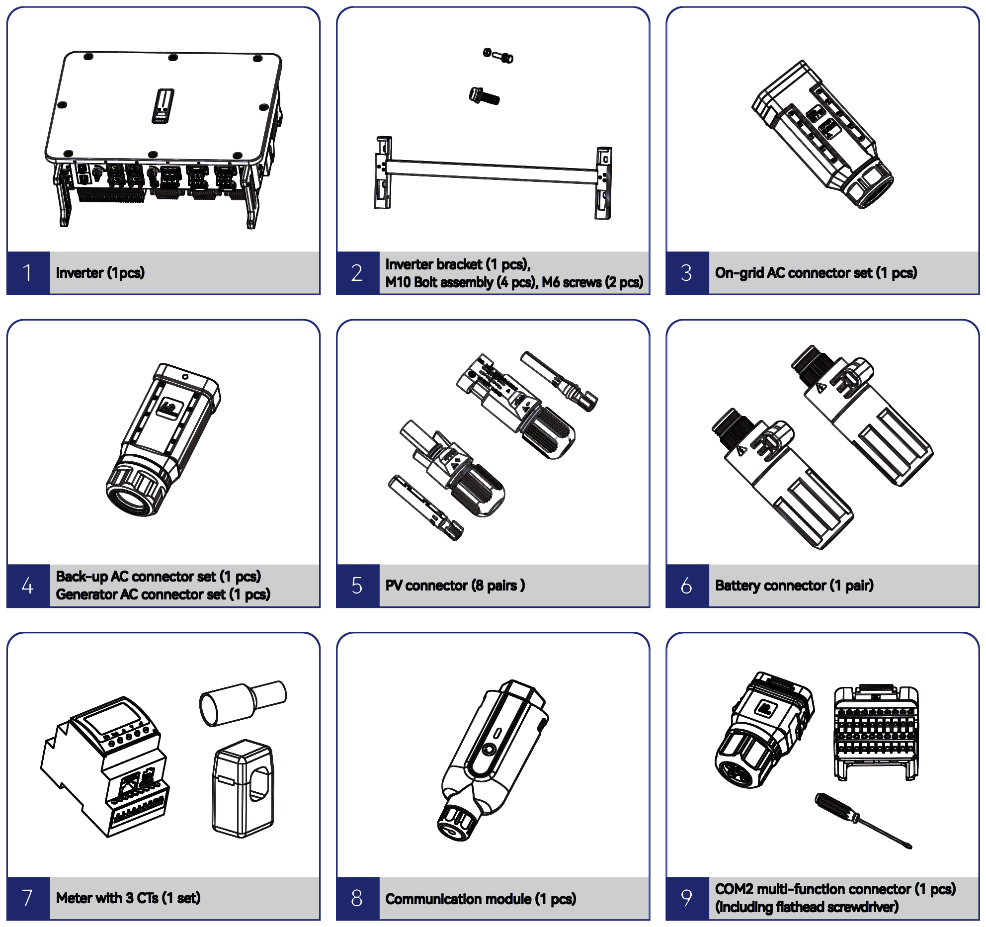
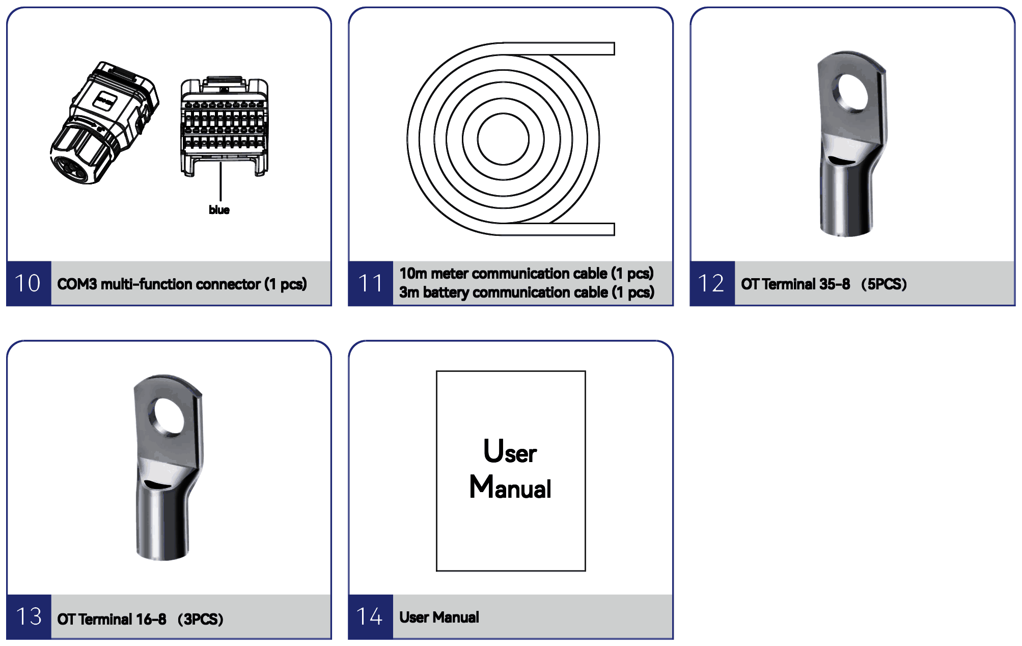
| No. | Item | Qty |
|---|---|---|
| 1 | Inverter | 1 |
| 2 | Mounting bracket, M10 bolt assemblies, M6 screws | 1, 4, 2 |
| 3 | On-grid AC connector set | 1 |
| 4 | Back-up AC connector set and generator AC connector set | 1 each |
| 5 | PV connectors | 8 pairs |
| 6 | Battery connectors | 1 pair |
| 7 | Smart meter with 3 CTs | 1 set |
| 8 | Communication module (R2MD) | 1 |
| 9 | COM2 multi-function connector, with flat-blade screwdriver | 1 |
| 10 | COM3 multi-function connector (blue) | 1 |
| 11 | Meter communication cable (10 m) and battery communication cable (3 m) | 1 each |
| 12 | OT lugs 35-8 | 5 |
| 13 | OT lugs 16-8 | 3 |
| 14 | User manual | 1 |
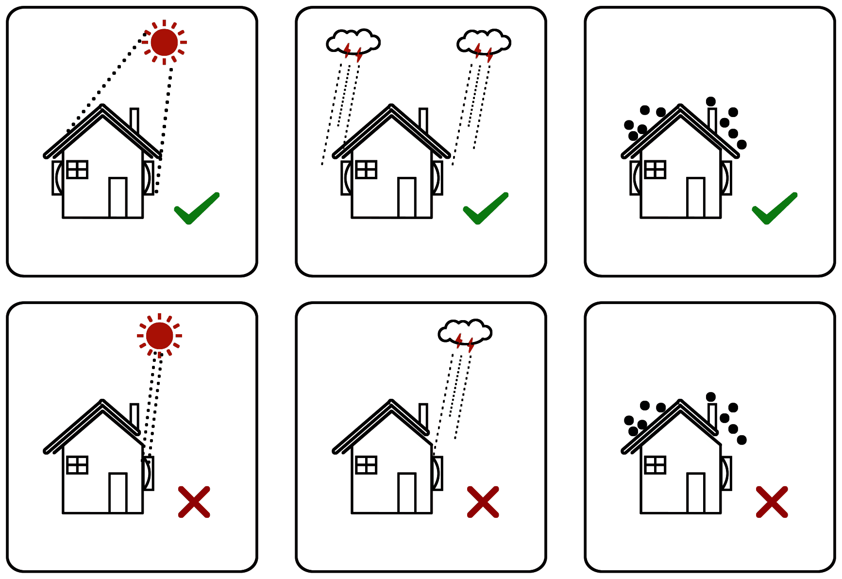
Do not keep flammable or explosive materials near the inverter.
Leave enough clearance around the inverter for cooling.
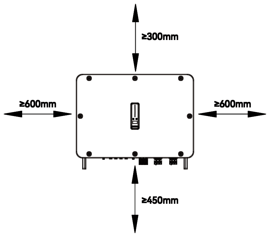
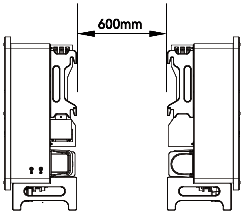
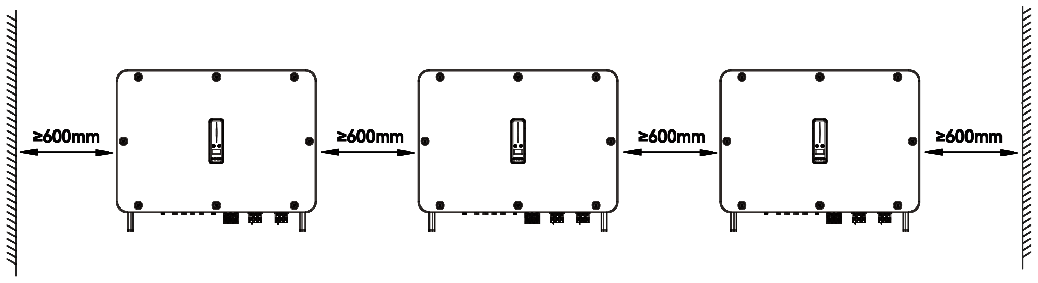
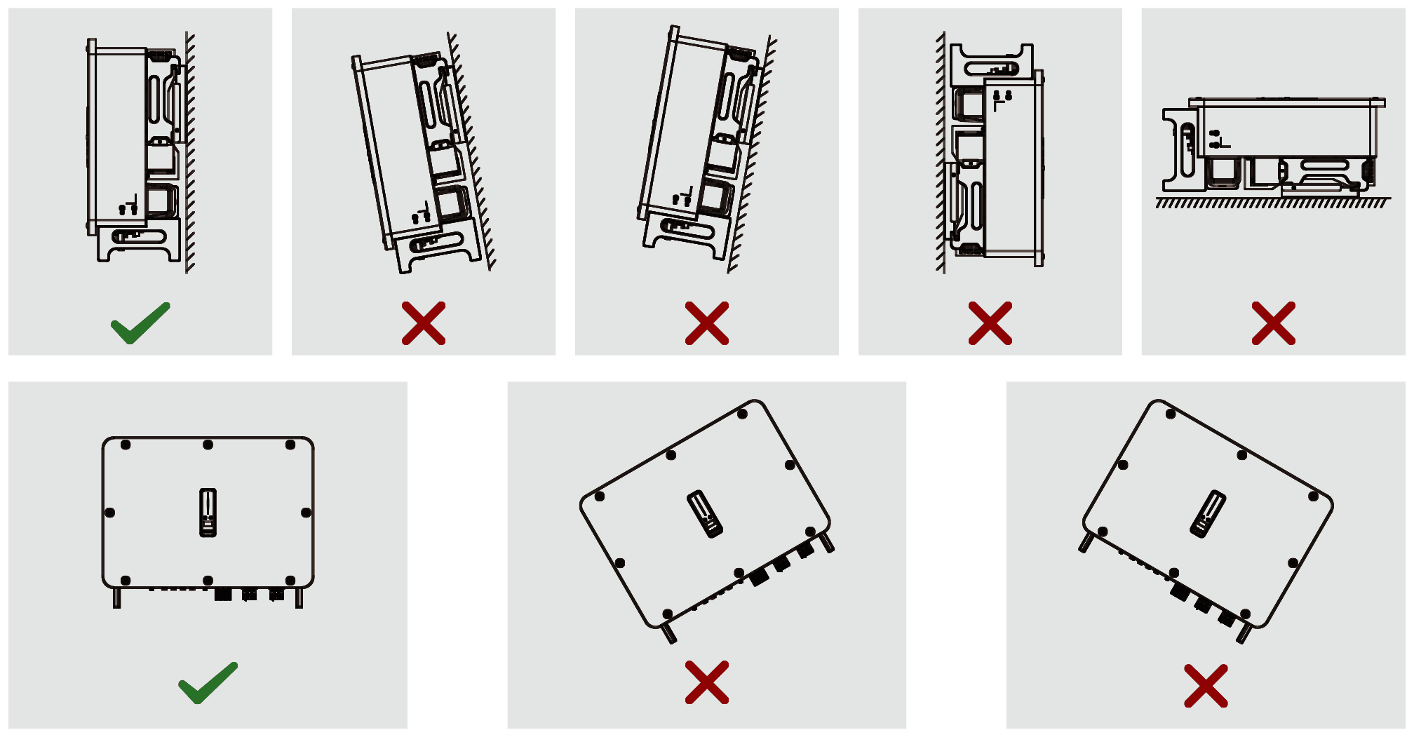
Install the inverter vertically. Never install it horizontally, tilted forwards or backwards, or upside down.
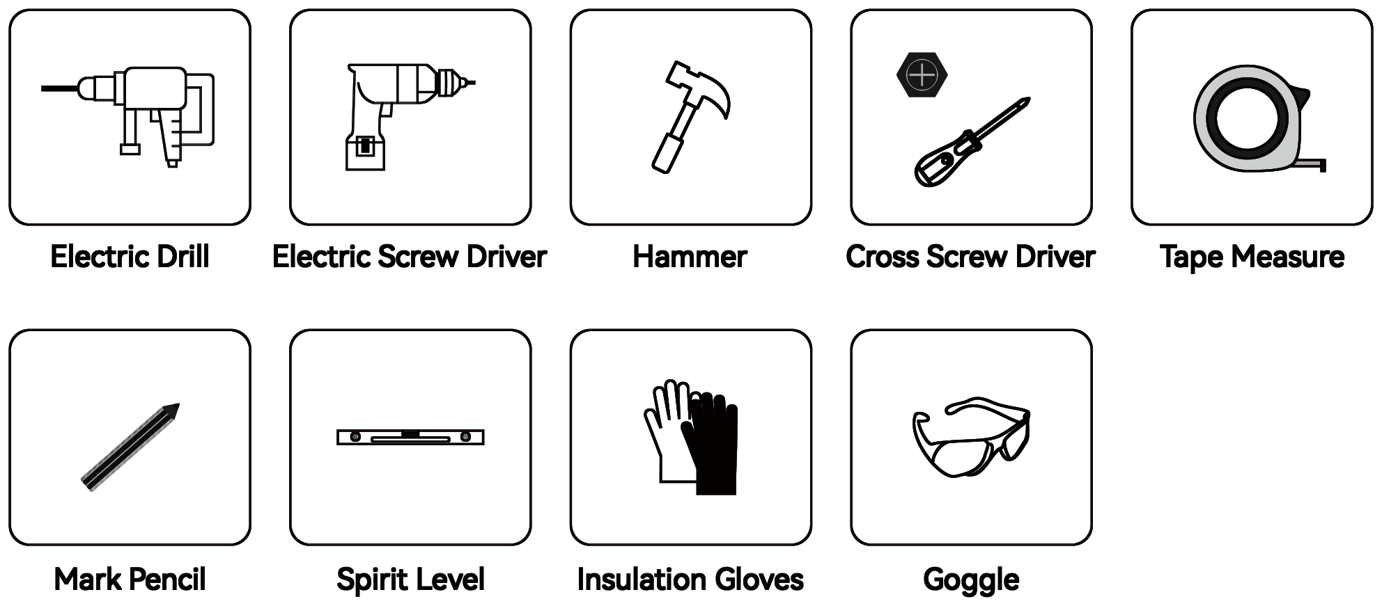
Wear PPE when installing. You will need an electric drill, electric screwdriver, hammer, Phillips screwdriver, tape measure, marker, spirit level, insulated gloves and safety glasses.
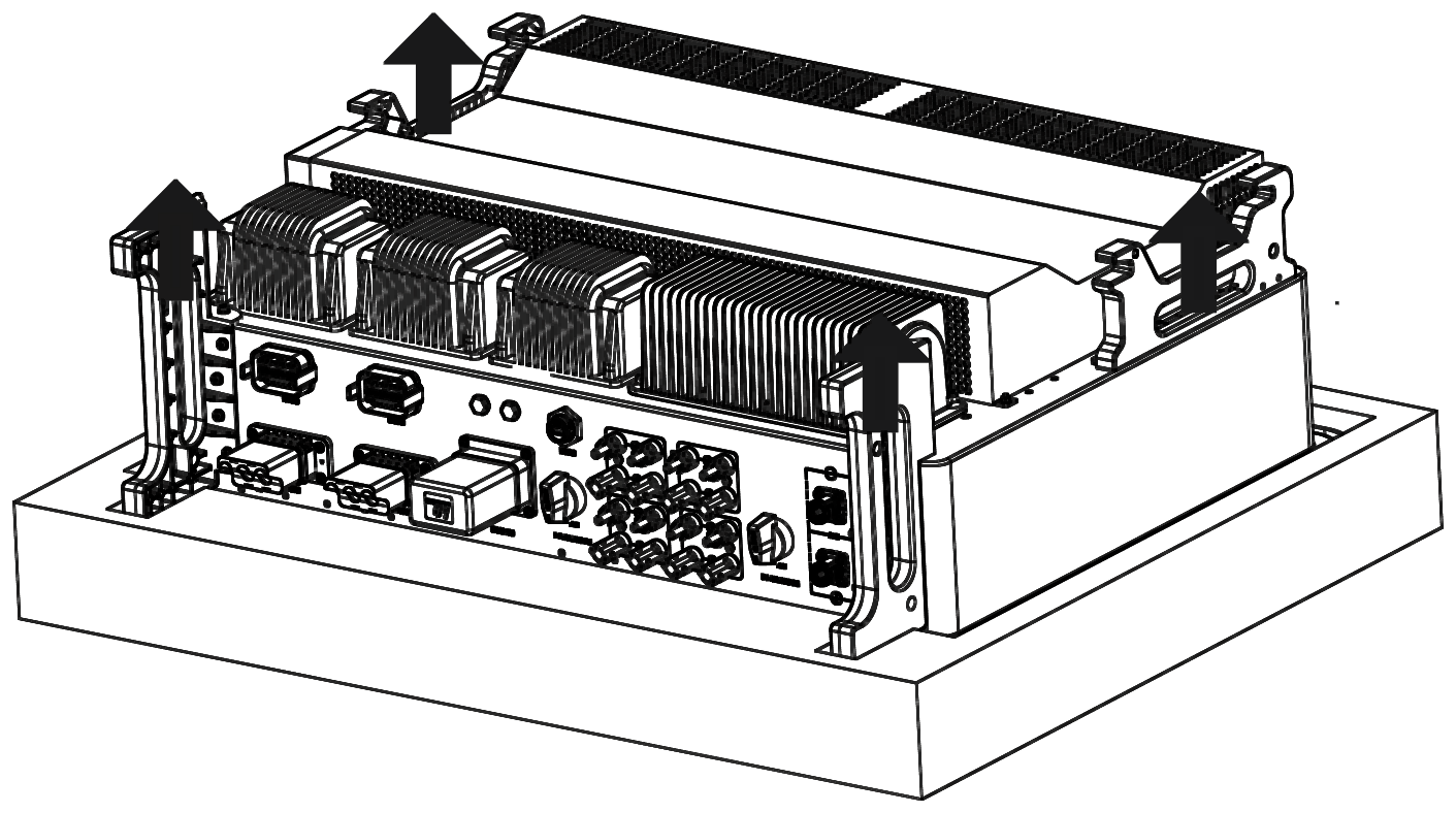
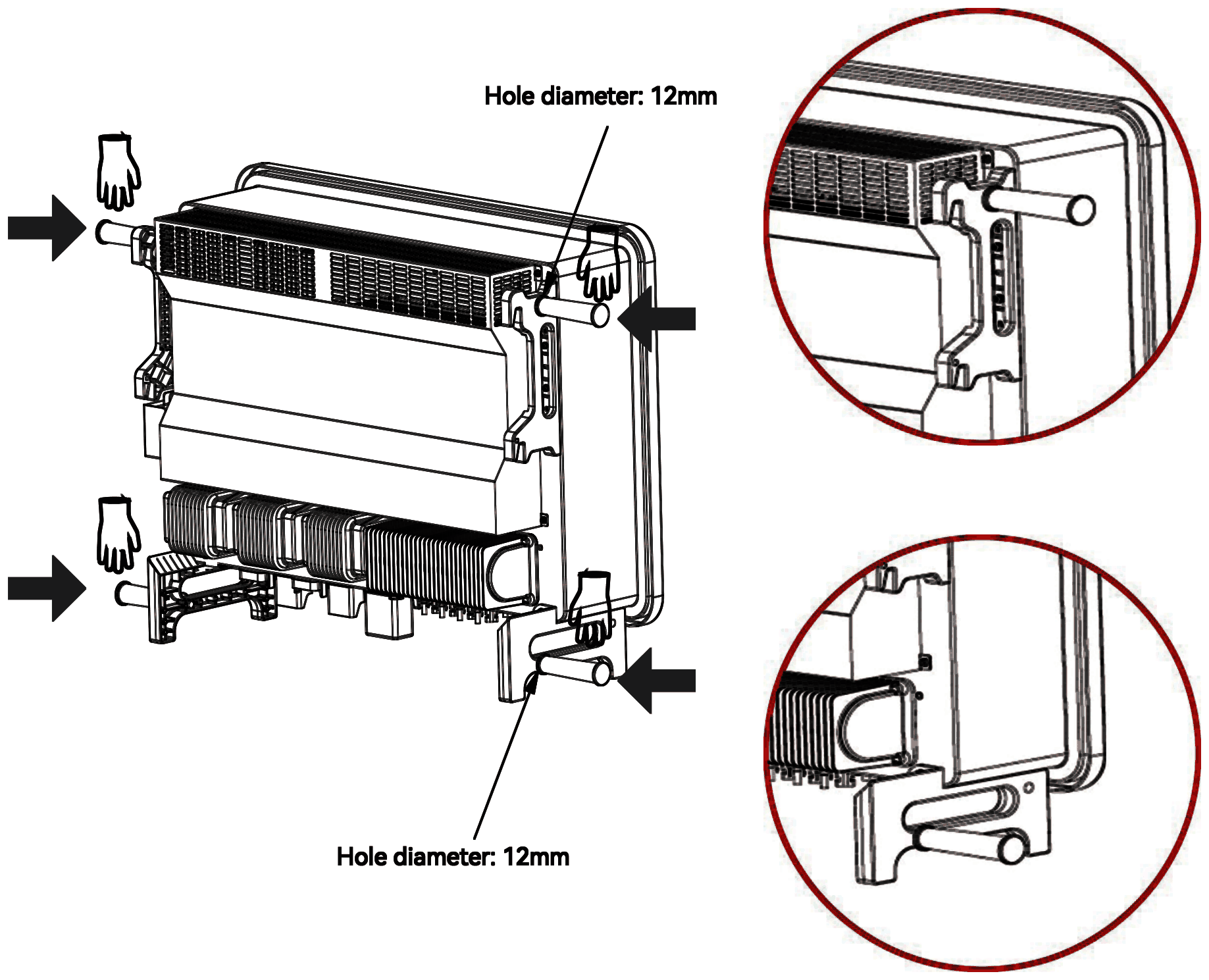
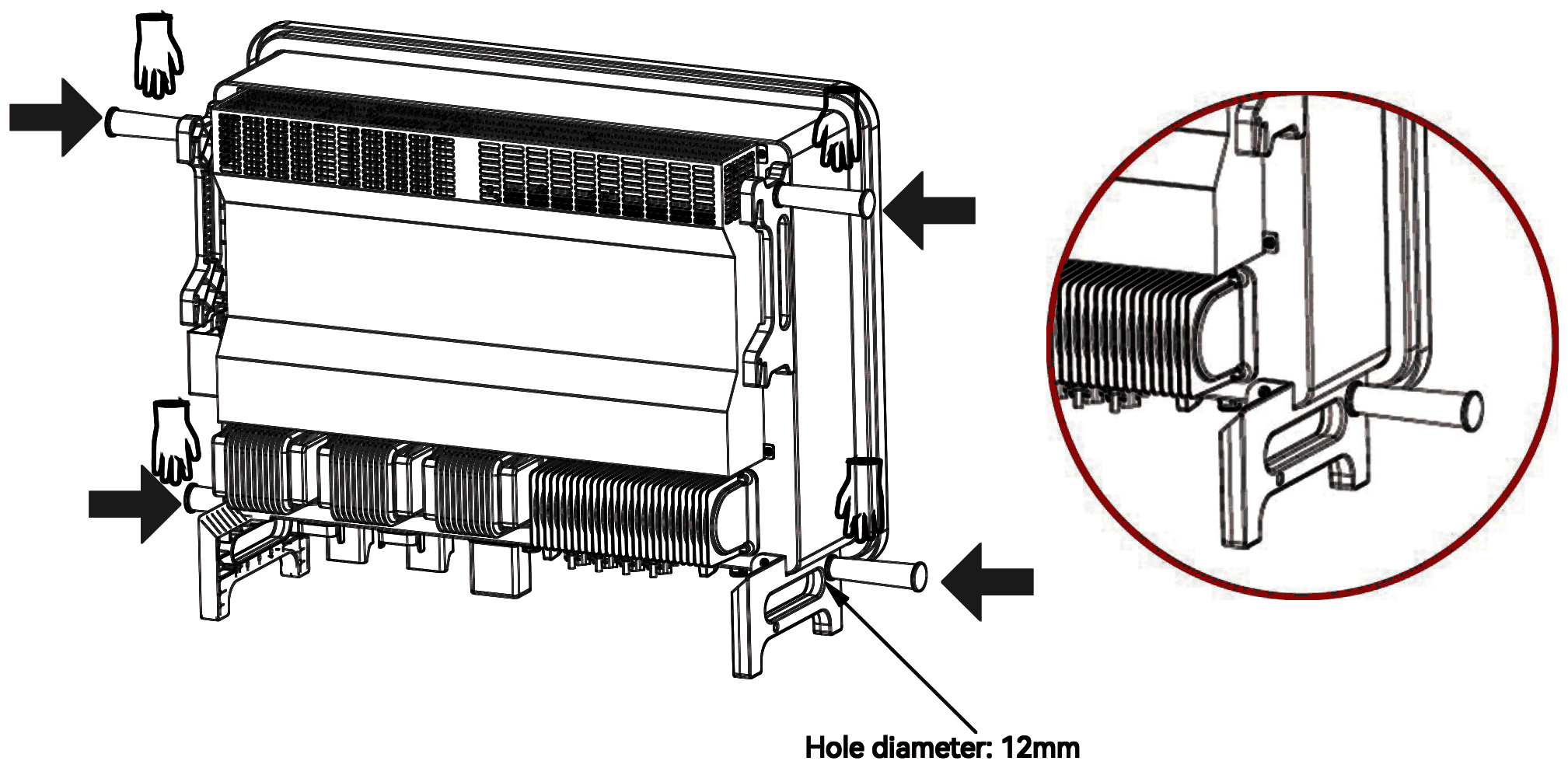
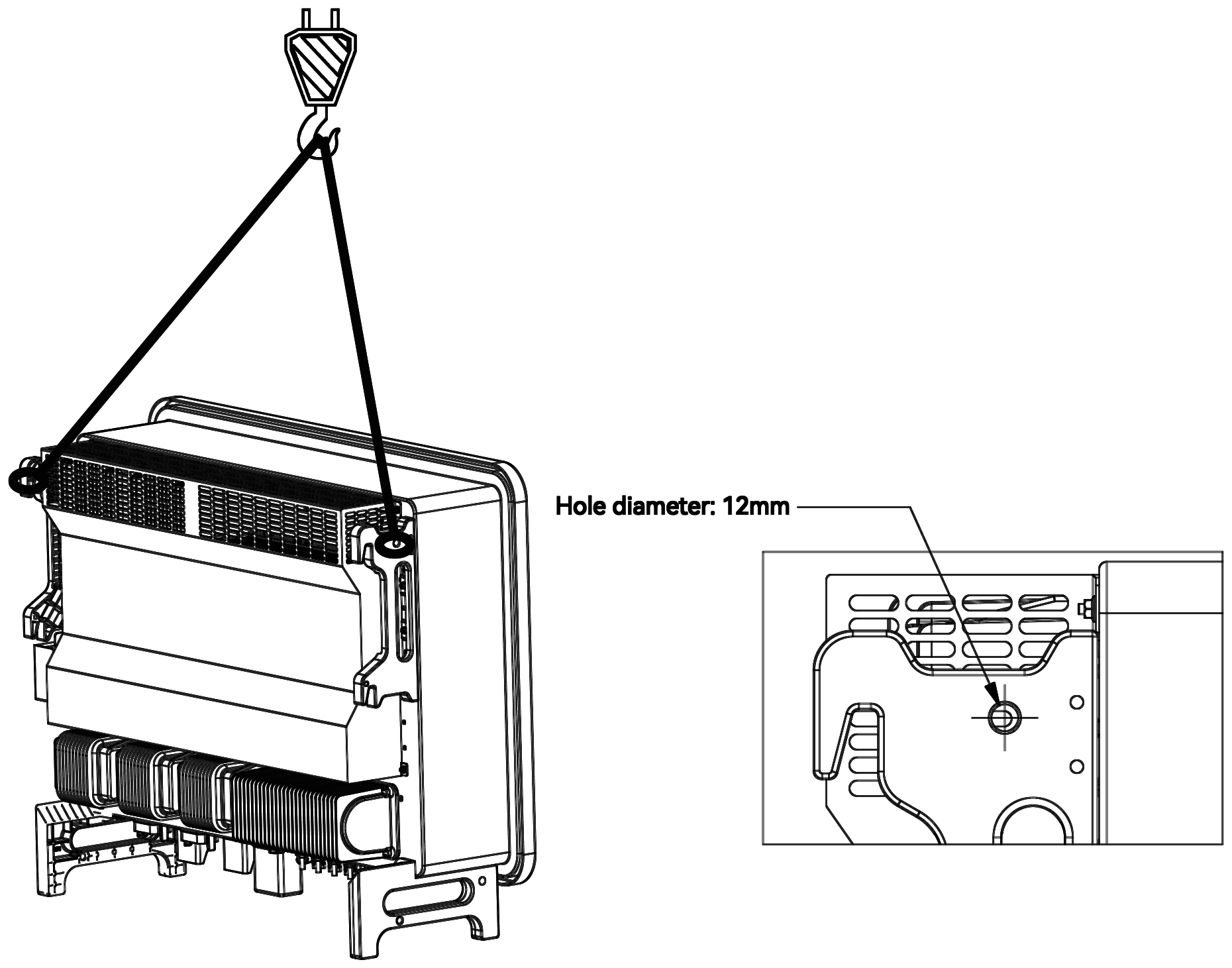
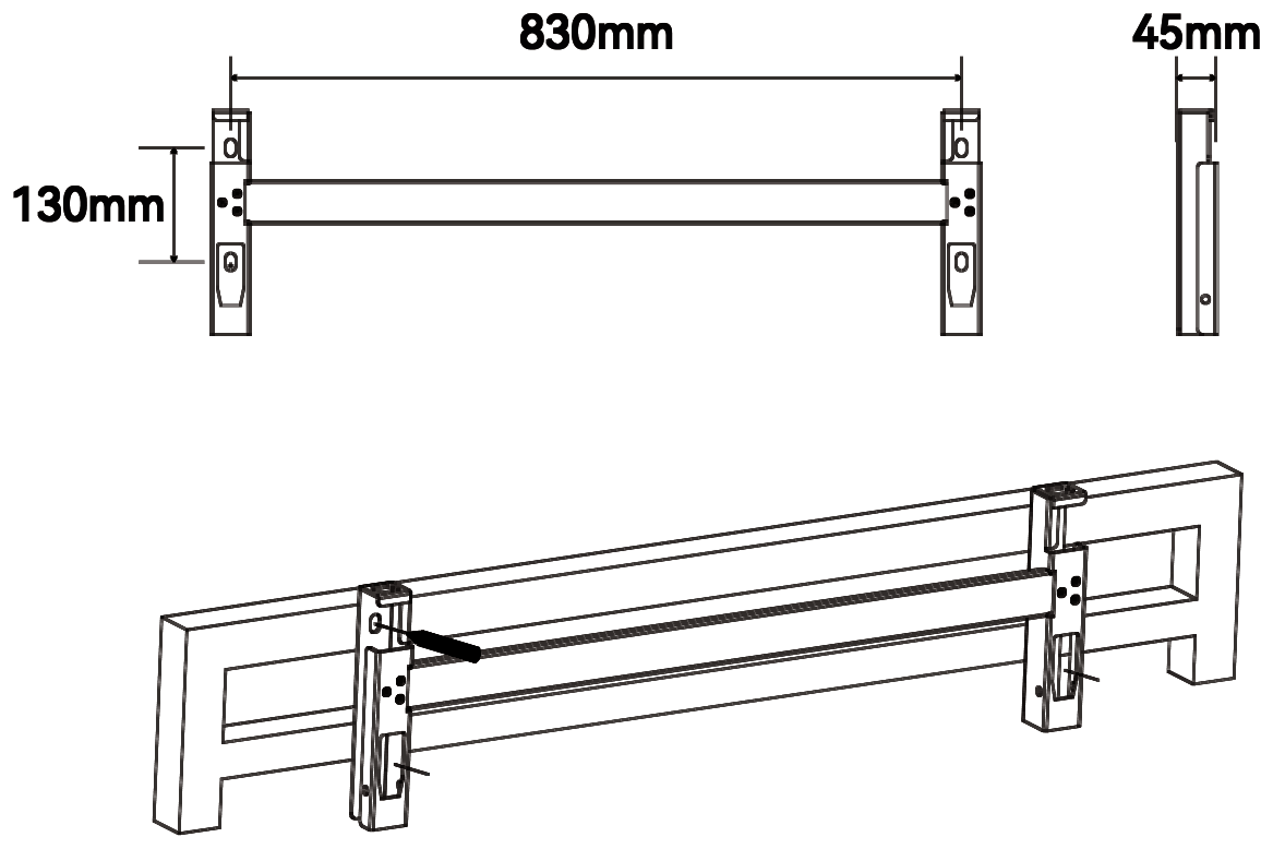
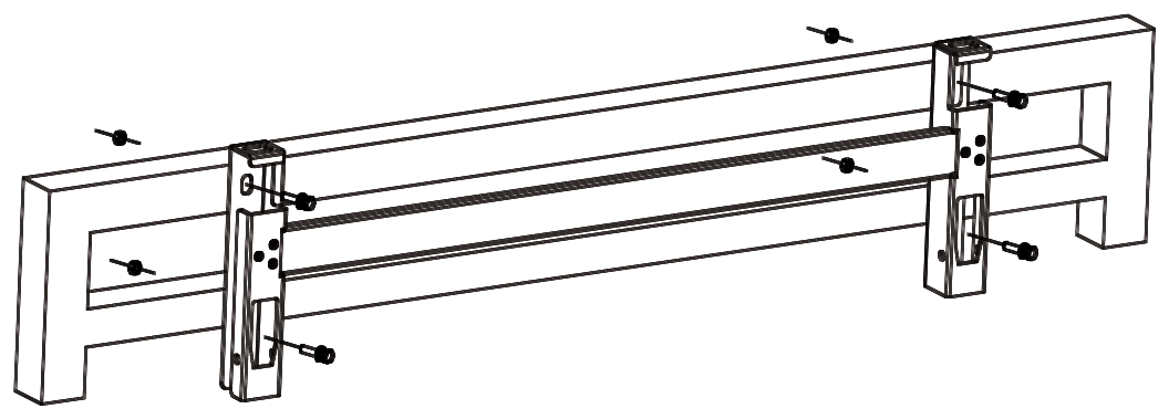
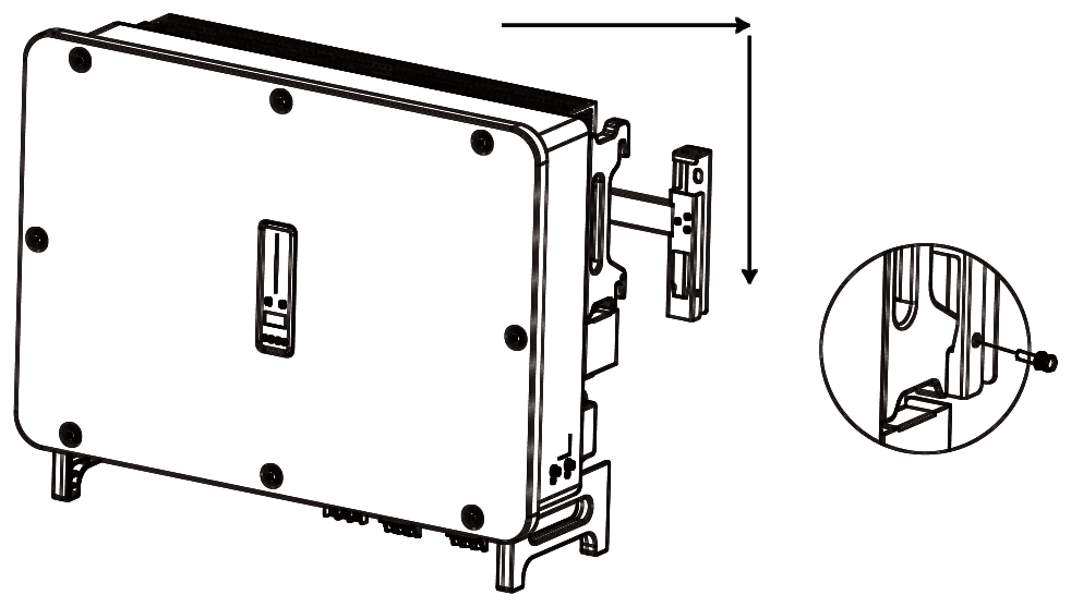
Connect the inverter to the earth bar with a PE conductor. Always connect the PE conductor before any other cable.
Never use the neutral as the protective earth for the inverter enclosure. Doing so can cause electric shock.
A reliable earth improves surge immunity and EMC performance. In a multi-inverter system, connect every inverter's PE conductor to the same earth bar for equipotential bonding.
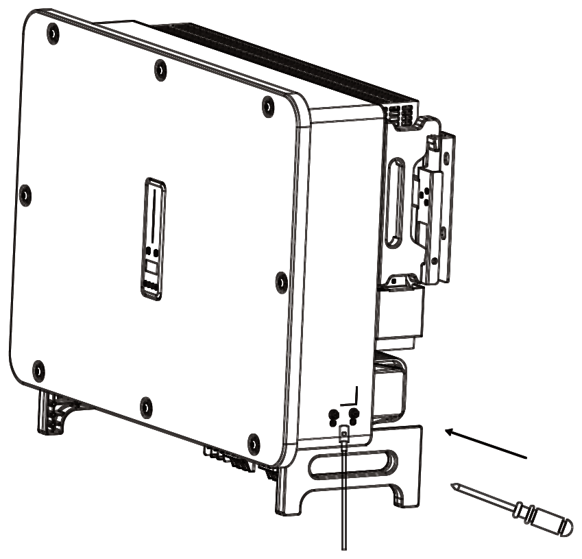
Make sure the AC and DC sides are fully isolated before working on the inverter. In sunlight, the PV array produces dangerous DC voltage. Follow these instructions exactly. The PV string voltage must never exceed the inverter's maximum DC input voltage. Damage caused by PV overvoltage is not covered by the warranty. Never use the neutral as the protective earth for the inverter enclosure.
Never earth the positive or negative pole of a PV string. This will seriously damage the inverter. The inverter is not suitable for functionally earthed PV arrays as described in AS/NZS 5033. Static electricity can damage the electronics. Take anti-static precautions during installation and maintenance.
Use only the terminals supplied in the accessory kit. Damage caused by other terminals is not covered. Tighten every cable gland securely. Damage from water or dust entering through a poorly fitted connector voids the warranty. If the back-up load is too large, the inverter protects itself and stops its AC output. Remove some of the load and restart the inverter.
The diagrams show the structure of a system with the RMM smart meter. Install and wire every system in accordance with local standards.
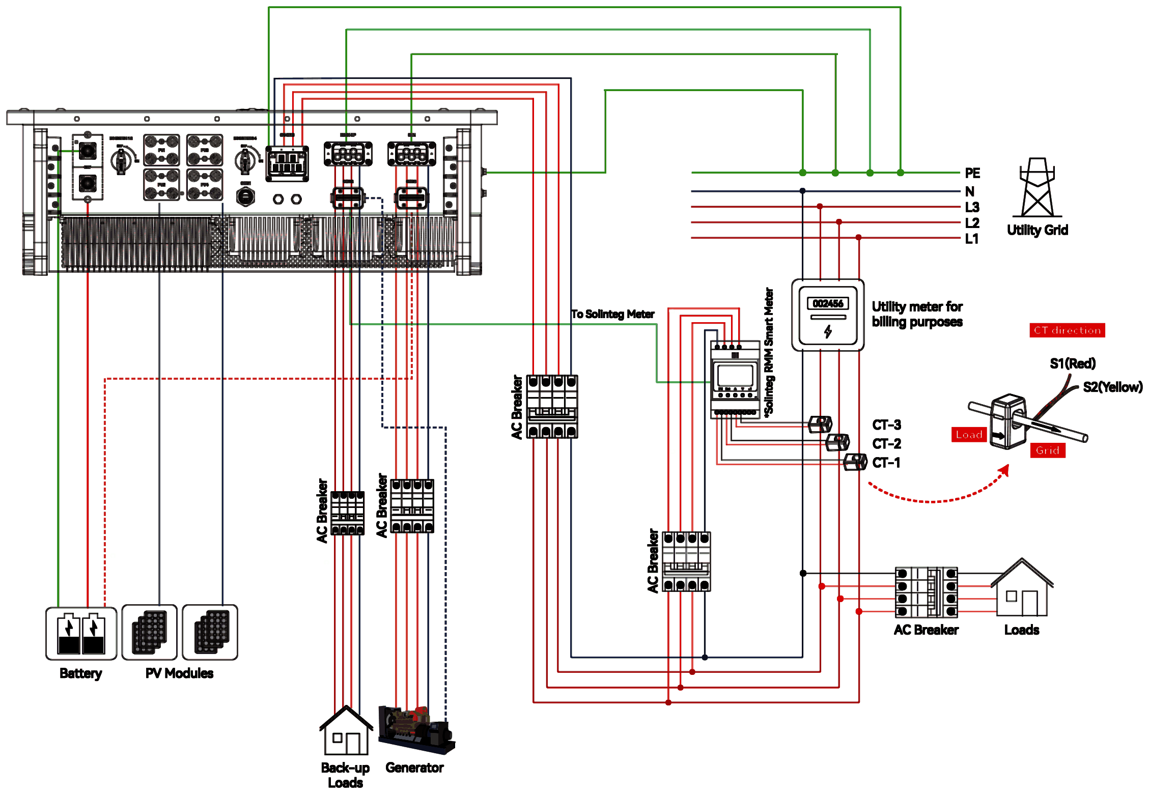
In Australia and New Zealand, the neutral must not be isolated or switched, and the neutrals of the grid side and the back-up side must be connected together in accordance with AS/NZS 3000. Otherwise the back-up function will not work.
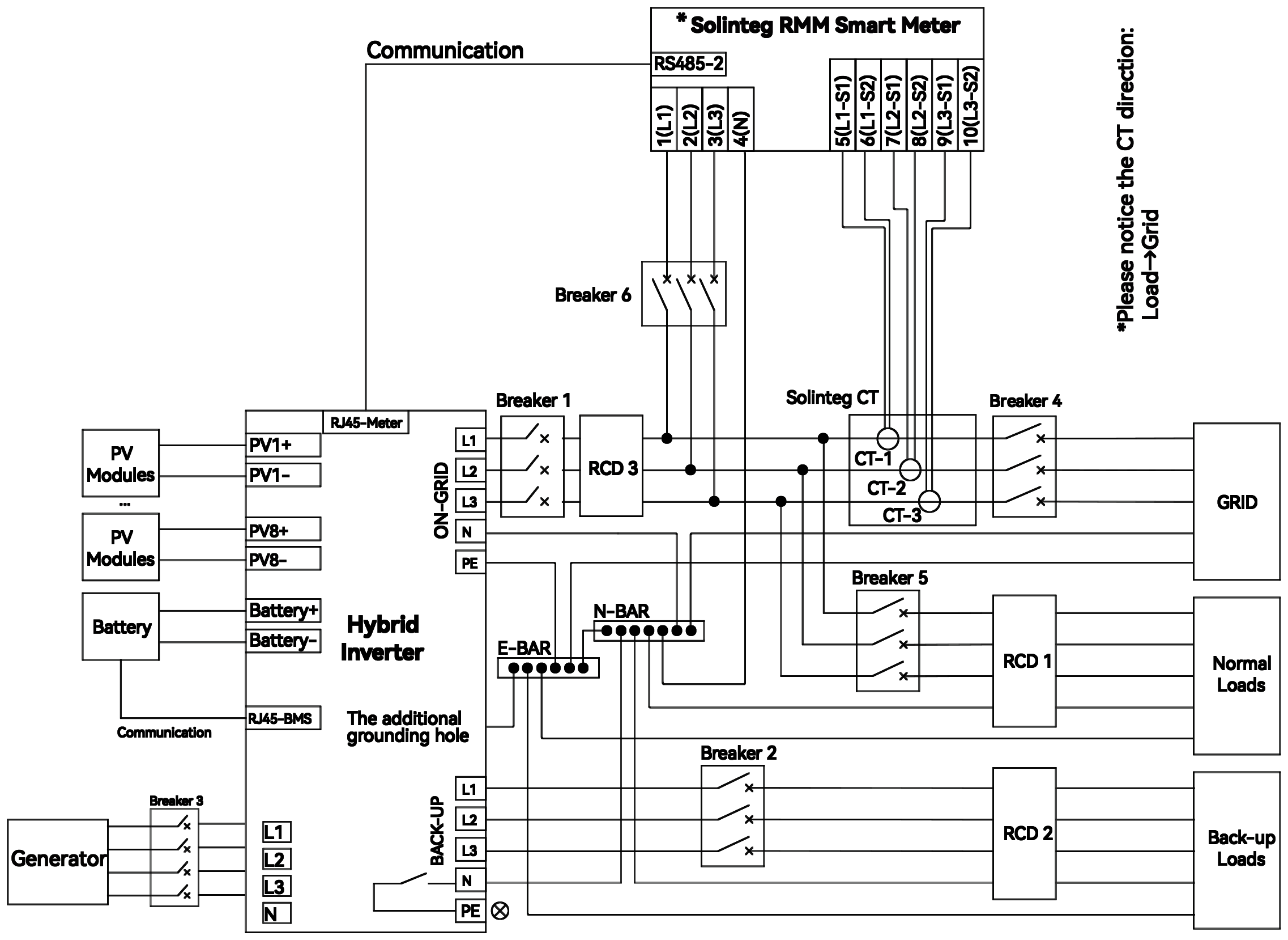
The inverter has built-in residual current monitoring and disconnects from the grid if the fault current exceeds its limit. If an external RCD is required, use type A. The table gives recommendations; select devices to suit the site and local regulations.
| Device | M2HT-25K | M2HT-29.9K / 30K | M2HT-40K | M2HT-50K |
|---|---|---|---|---|
| Breaker 1 (on-grid) | 100 A / 400 V AC | 125 A / 400 V AC | 160 A / 400 V AC | 160 A / 400 V AC |
| Breaker 2 (grid supply) | 100 A / 400 V AC | 125 A / 400 V AC | 160 A / 400 V AC | 160 A / 400 V AC |
| Breaker 3 (back-up) | 63 A / 400 V AC | 80 A / 400 V AC | 100 A / 400 V AC | 125 A / 400 V AC |
| Breaker 6 (meter) | 6 A / 400 V AC | 6 A / 400 V AC | 6 A / 400 V AC | 6 A / 400 V AC |
| Device | M2HT-25K | M2HT-29.9K / 30K | M2HT-40K | M2HT-50K |
|---|---|---|---|---|
| RCD 1 and RCD 2 | 30 mA type A | 30 mA type A | 30 mA type A | 30 mA type A |
| RCD 3 | 300 mA type A | 300 mA type A | 400 mA type A | 500 mA type A |
| Conditional short-circuit current | 10 kA | 10 kA | 10 kA | 10 kA |
| Minimum prospective short-circuit current | 1 kA | 1.25 kA | 1.6 kA | 1.6 kA |
Breaker 4 (main switchboard) is sized to suit the site loads and inverter capacity, and breaker 5 to suit the normal loads. Short-circuit values are to IEC 62477.
Some countries require the back-up neutral to be earthed when the inverter operates off-grid. With the N-PE Check setting on, the inverter links N to PE in off-grid operation and disconnects the link in on-grid operation. In Australia, the MEN link in the switchboard normally provides this. Set N-PE Check to suit the installation design.
You need the inverter accessory kit, and wire strippers, side cutters, crimping tools (including an RJ45 crimper), a multimeter with a DC range above 1100 V, screwdrivers and an Allen socket wrench. Supply AC, DC, communication and earth cables to suit the site.
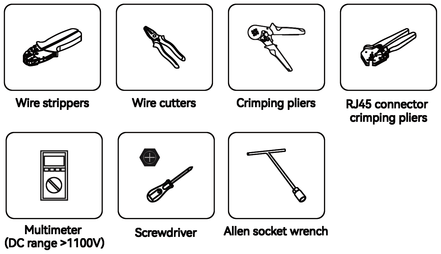
Isolate every AC and DC supply before connecting the AC cables. Connect the phases in the correct order, as marked on the AC connectors.
Each of the on-grid and back-up outputs needs its own AC breaker. Do not connect loads directly to the inverter. Fit RCDs on the AC side as local regulations require. The inverter suits three-phase grids of 380/400/415 V, 50/60 Hz. Connect to the grid only with the approval of the local network service provider.
| Cable | Outside diameter | Conductor size |
|---|---|---|
| On-grid: 5-core AC cable | 20–37 mm | 16–50 mm² |
| Back-up and generator: 5-core AC cable | 20–30 mm | 10–25 mm² flexible, 10–35 mm² rigid |
High voltage may be present in the inverter. Check that every cable is dead before connecting it, and do not switch on any AC breaker until all connections are complete.
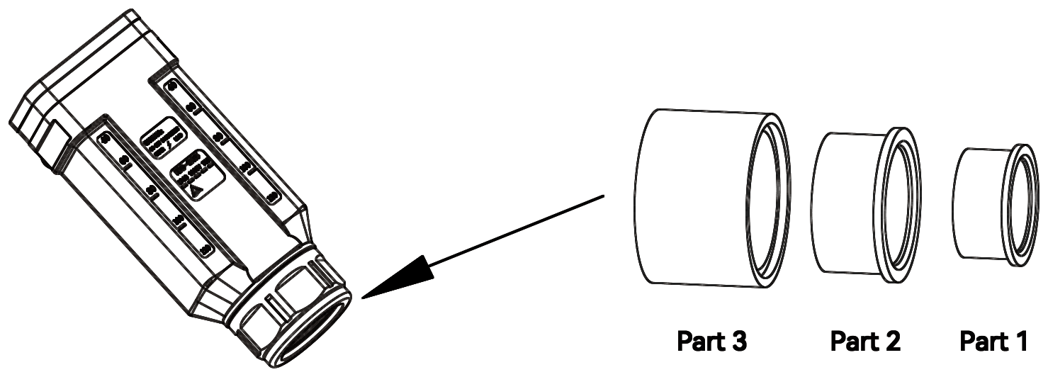
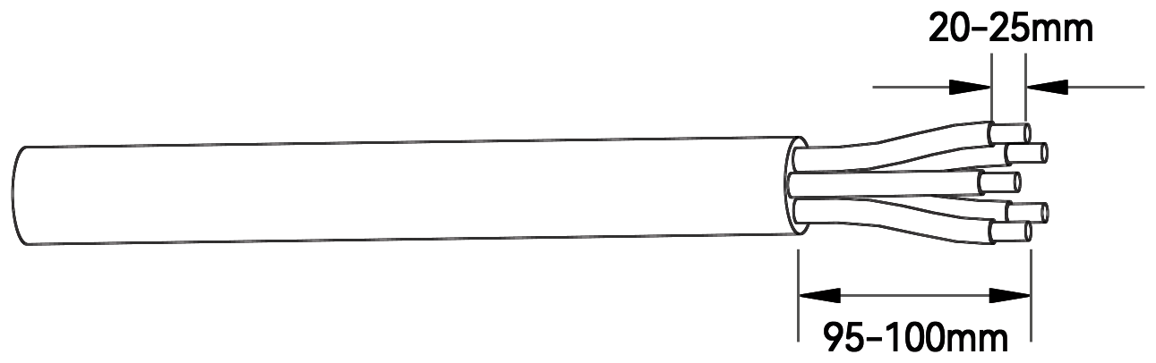
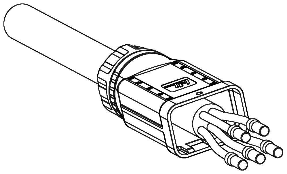
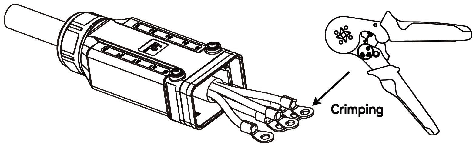
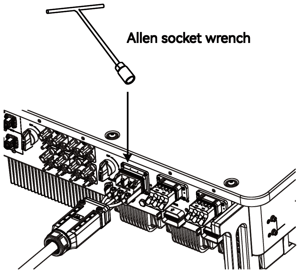
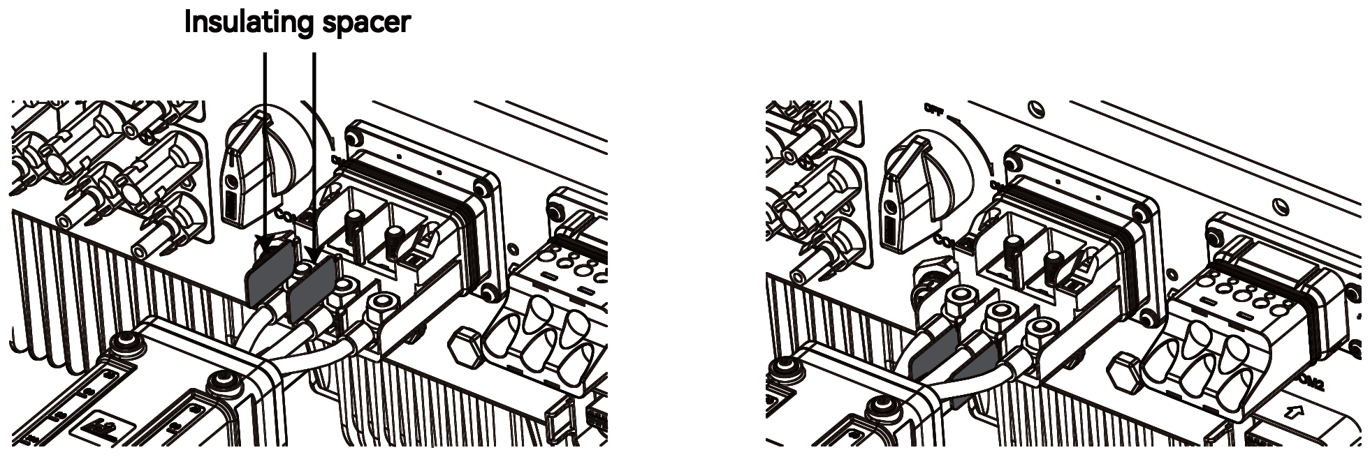
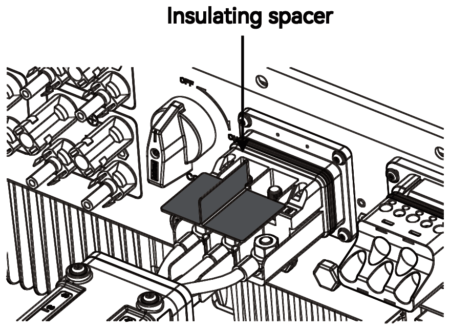
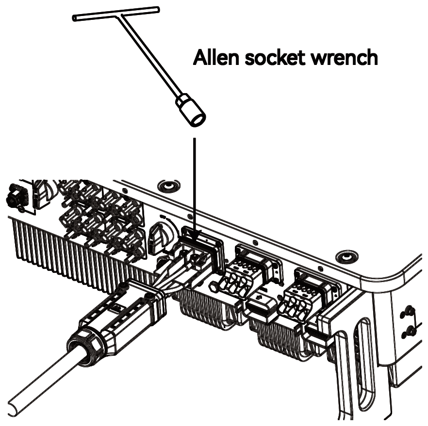
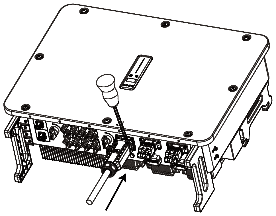
Do not confuse the back-up and generator cables when connecting them to the inverter.
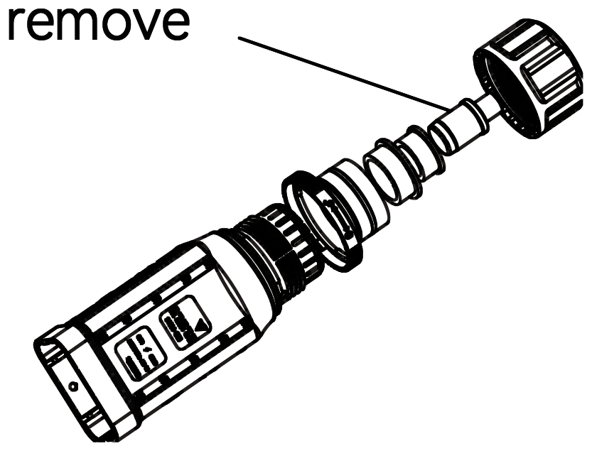
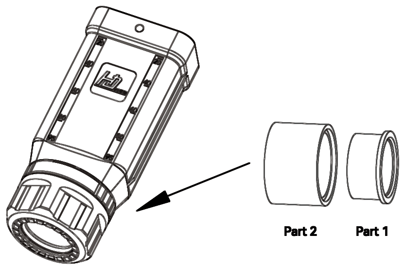
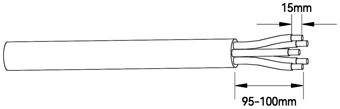
Make sure the ferrules are clamped tightly, so they cannot loosen over time.
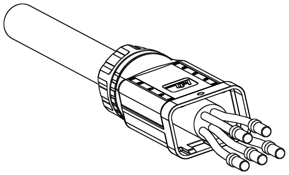
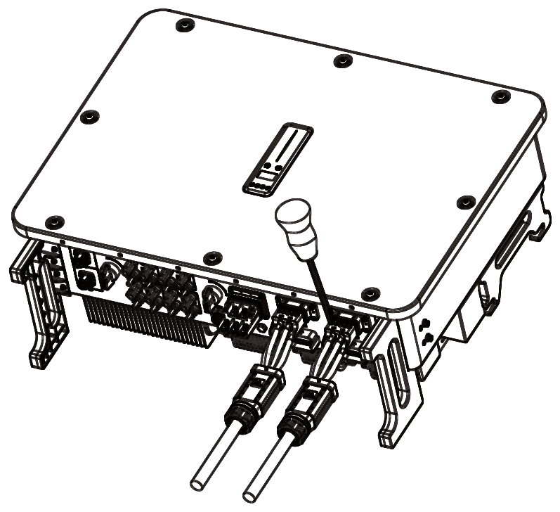
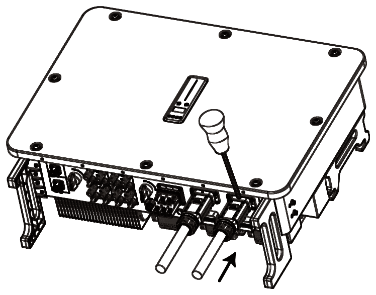
In sunlight, the PV array produces dangerous DC voltage.
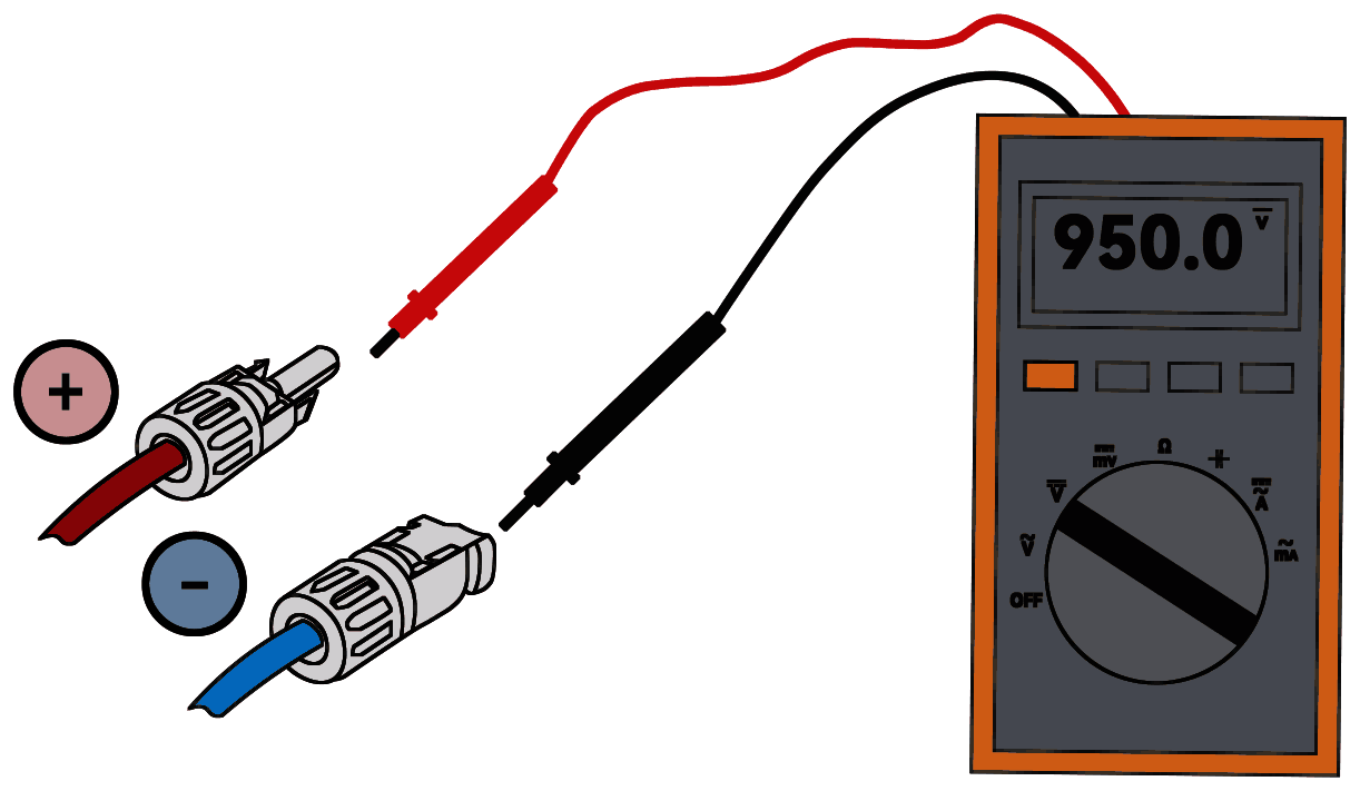
Check the polarity of each string before connecting it. The maximum operating PV input voltage is 950 V. Between 950 V and 1000 V the inverter goes to standby. Above 1000 V the inverter will be damaged. Make sure the PV connectors are fully mated, to prevent overheating or arcing.
The modules on one MPPT should be the same brand and model, at the same tilt and orientation, with the same string voltage. Otherwise energy yield may be reduced.
| Cable | Outside diameter | Conductor size |
|---|---|---|
| DC (PV) cable | 5.9–8.8 mm | 4 mm² (12 AWG) or 6 mm² (10 AWG) |
Where an external DC isolator is required, it must be certified to AS 60947.3:2018 and AS/NZS IEC 60947.1:2020 in Australia and New Zealand. Select it to suit the inverter's maximum DC short-circuit current (50 A per MPPT).
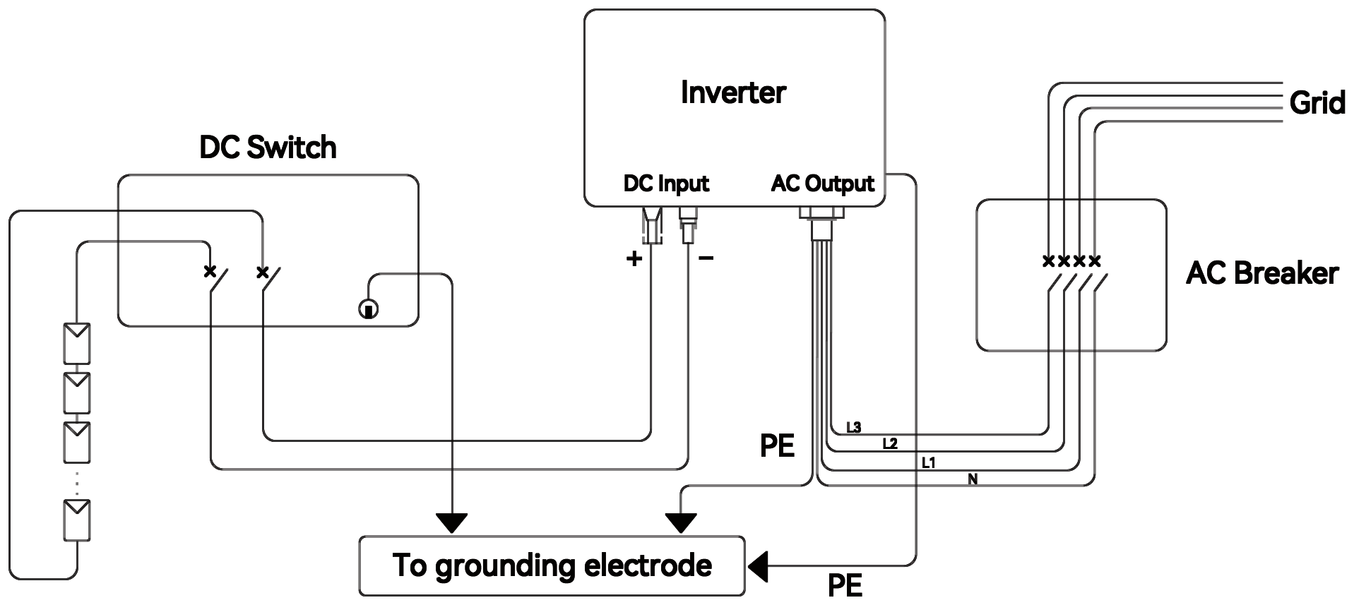
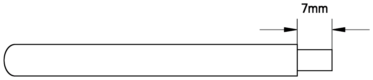

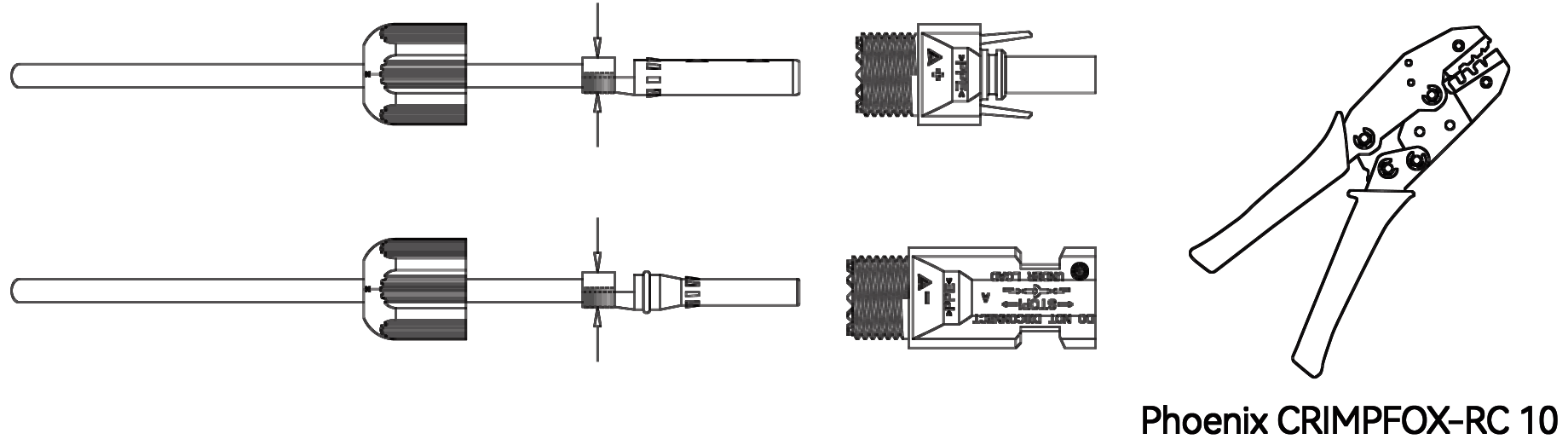
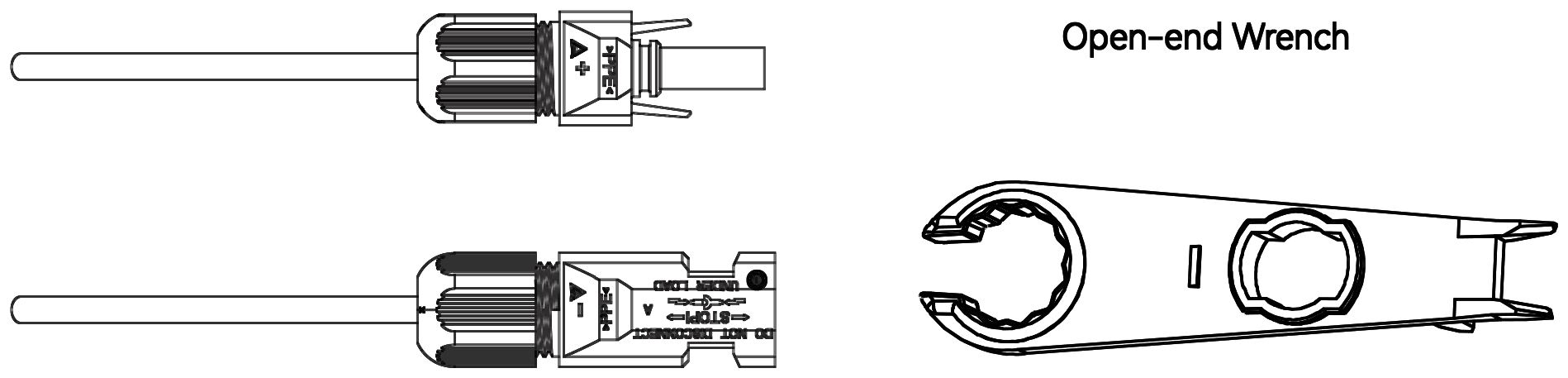
This section covers the inverter side only. For the battery side, follow the battery manufacturer's instructions.
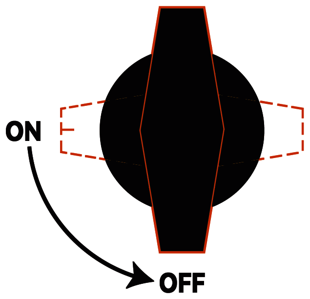
Before connecting the battery, switch off the AC breakers and the battery breaker, and turn the inverter DC switch to OFF. Check the polarity before connecting.
The maximum battery voltage is 840 V. Measure the battery voltage before connecting it, and never connect a battery above 840 V. Fit fuses in both the positive and negative battery conductors.
The inverter cannot operate off-grid without a battery. The inverter works only with batteries on Solinteg's compatibility list: high-voltage LFP batteries with a BMS. See the AERL Compatibility Guide (aerl.com.au).
| Cable | Outside diameter | Conductor size |
|---|---|---|
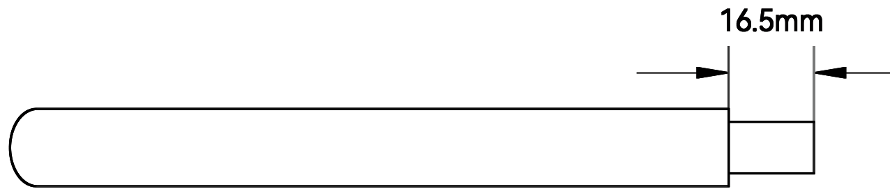
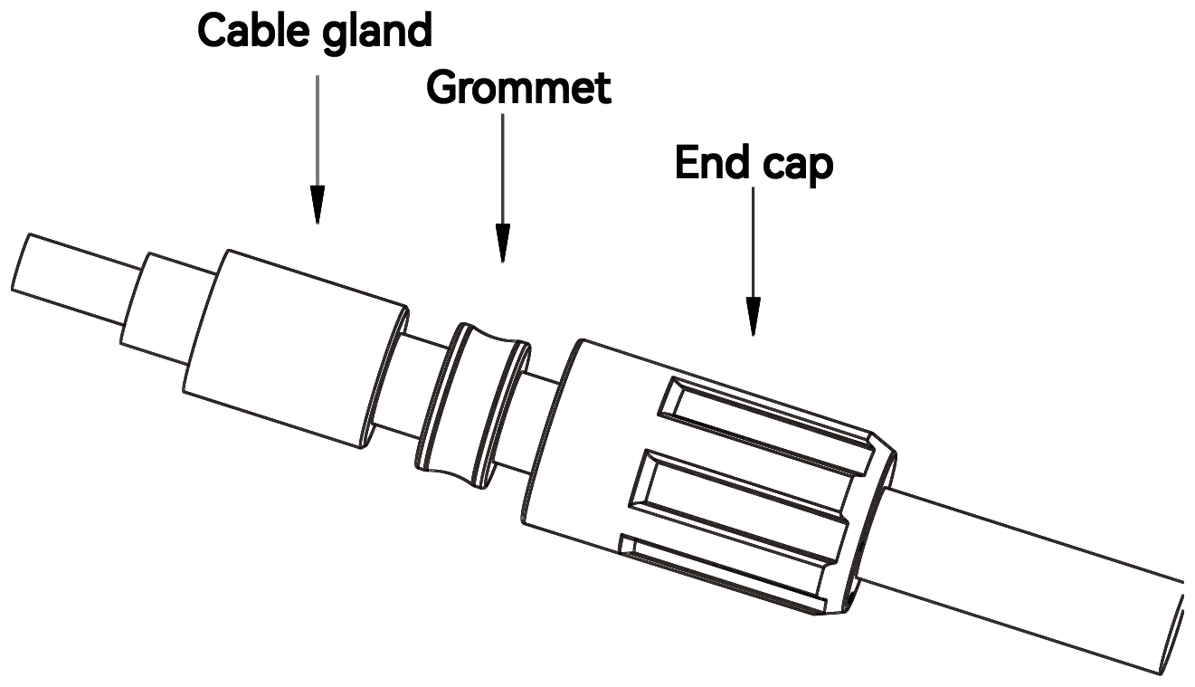
| Battery DC cable | 13 ± 0.5 mm | 50 mm² |
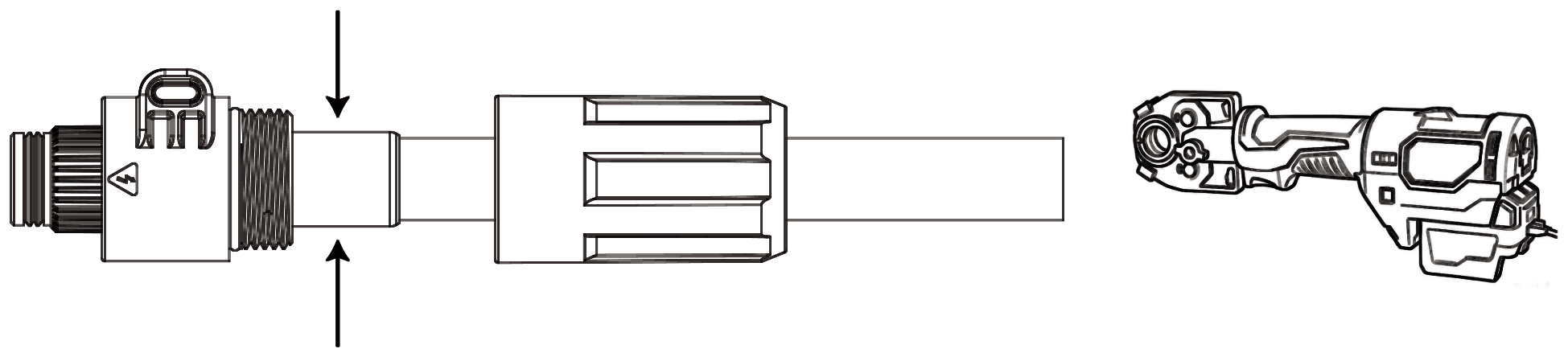
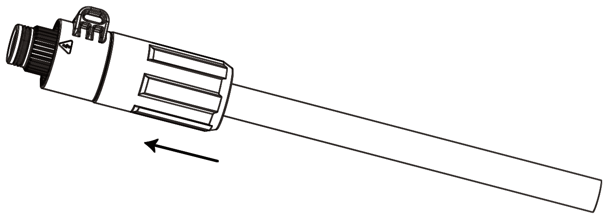
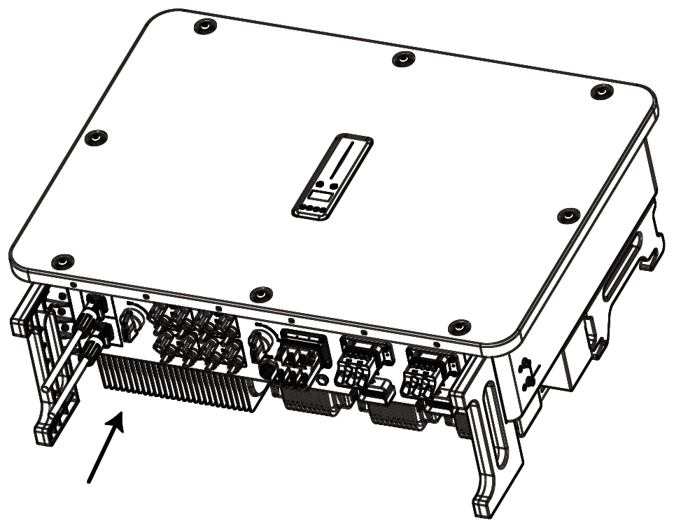
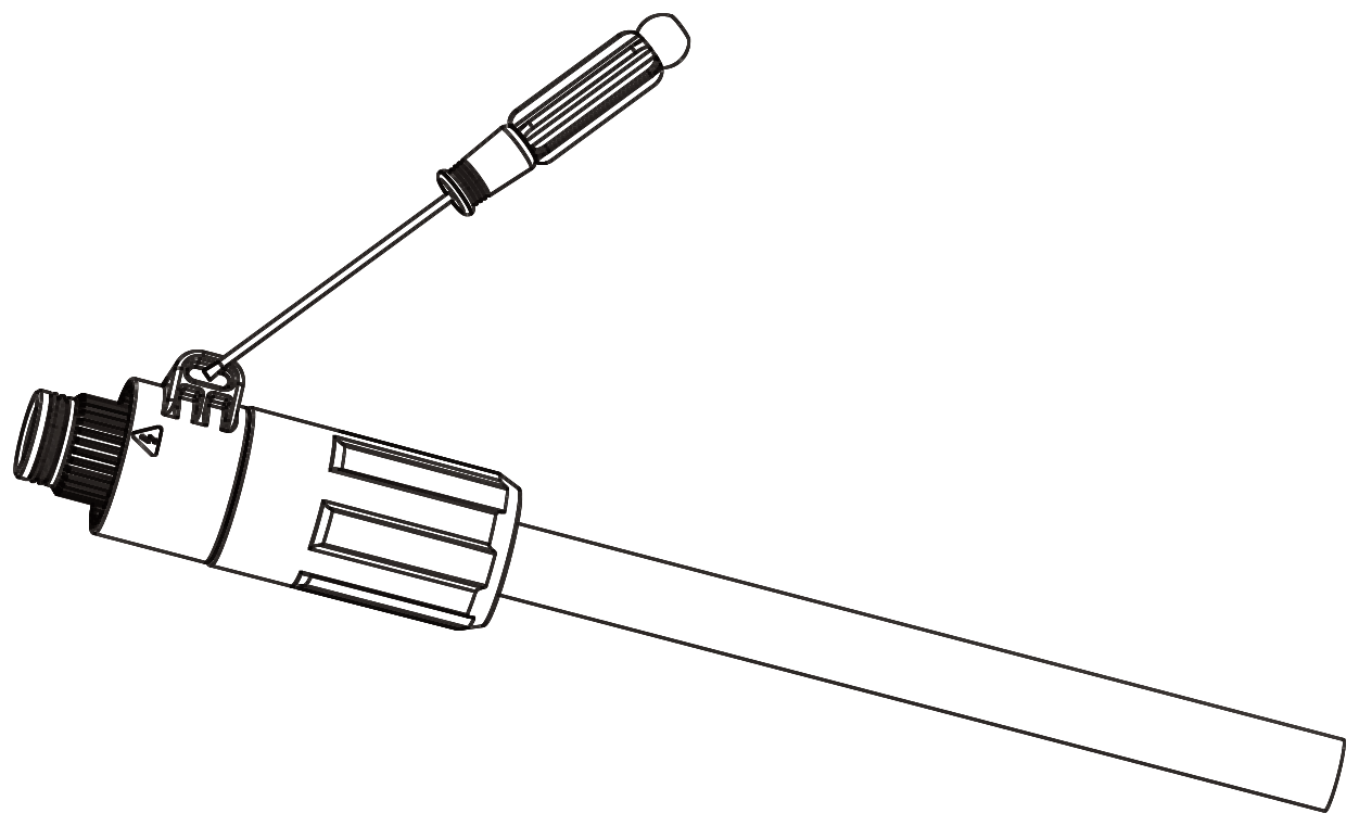
The battery communication cable is covered in section 5.9.
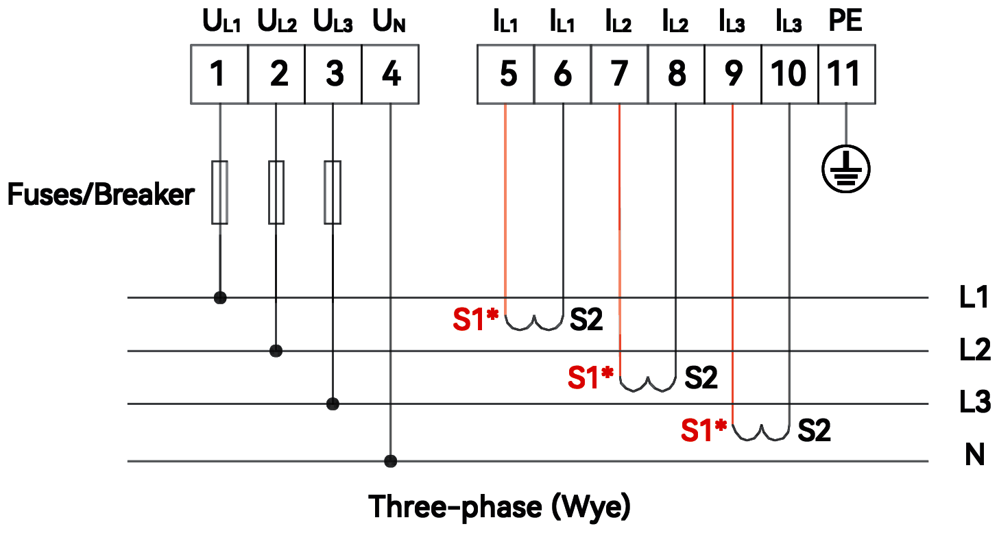
The system needs the Solinteg RMM smart meter and CTs for load monitoring, export limiting and power management. Both are supplied with the inverter, with the CTs pre-wired to the meter; do not disconnect them. The CT leads are 2 m long.
Install the meter in the switchboard or another suitable location out of reach of children. Fit the CTs on the phase conductors between the grid and the on-grid loads, with the arrows pointing from the loads to the grid.
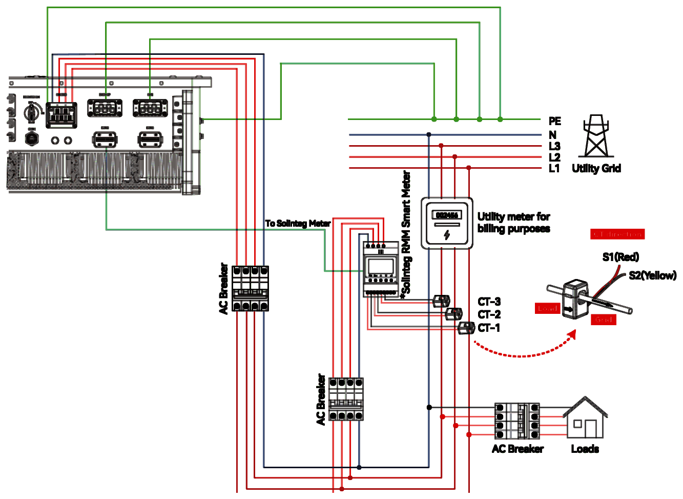
Use only smart meters compatible with Solinteg systems. Fit a circuit breaker in the meter's AC supply. Install each CT with its arrow pointing from the loads to the grid.
| Terminal | Signal | Function |
|---|---|---|
| 1, 2, 3, 4 | UL1, UL2, UL3, UN | Grid voltage sensing |
| 5, 6 | IL1 S1, IL1 S2 | CT 1 |
| 7, 8 | IL2 S1, IL2 S2 | CT 2 |
| 9, 10 | IL3 S1, IL3 S2 | CT 3 |
| 11 | PE | Earth |
| RS485-2 | A, B | Communication with the inverter |
| CT model | Inside diameter | Rated current | Ratio |
|---|---|---|---|
| D16-120A | 16 mm | 120 A | 1200:1 |
| D24-200A | 24 mm | 200 A | 2000:1 |
| D35-300A | 35 mm | 300 A | 3000:1 |
Choose the CT to suit the load and the inverter rating when ordering. The RMM-5A meter needs separately purchased 5 A CTs; see its manual.
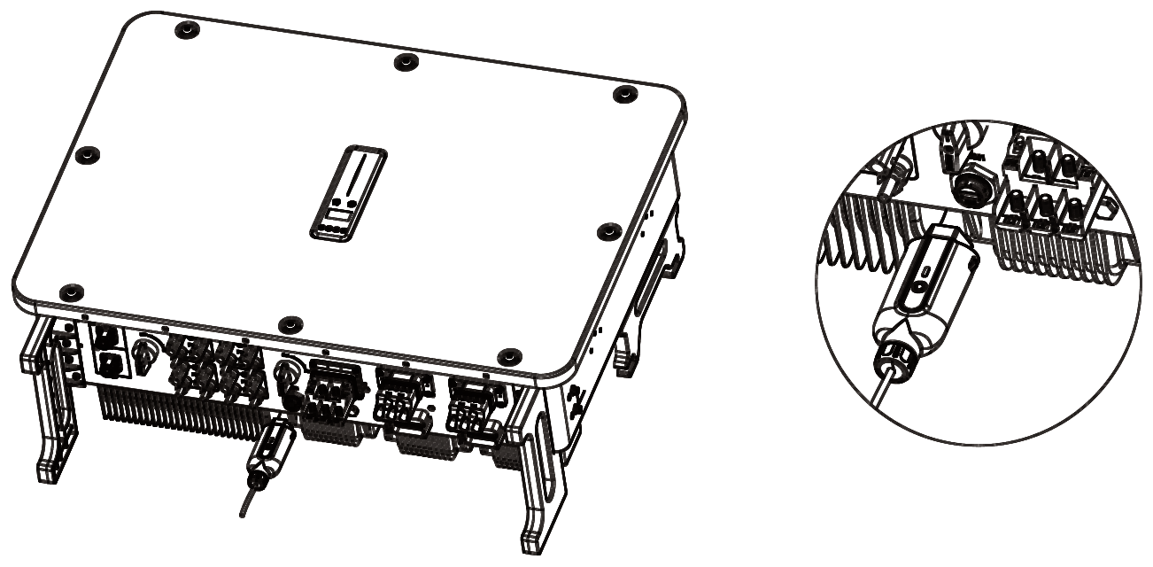
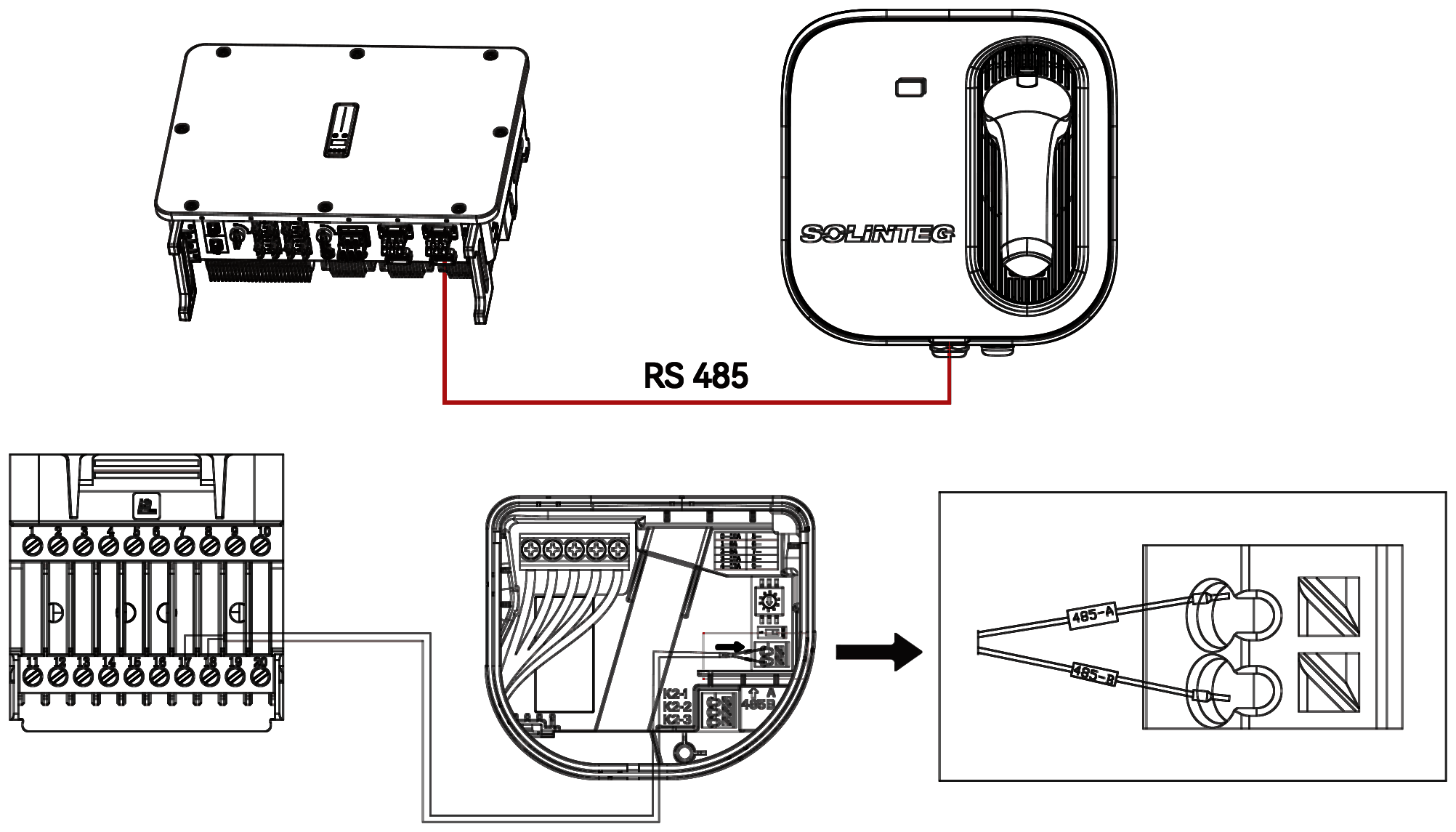
The inverter works only with the Solinteg R2MD communication module, supplied in the accessory box.
The inverter communicates with other devices through the COM2 and COM3 multi-function connectors.
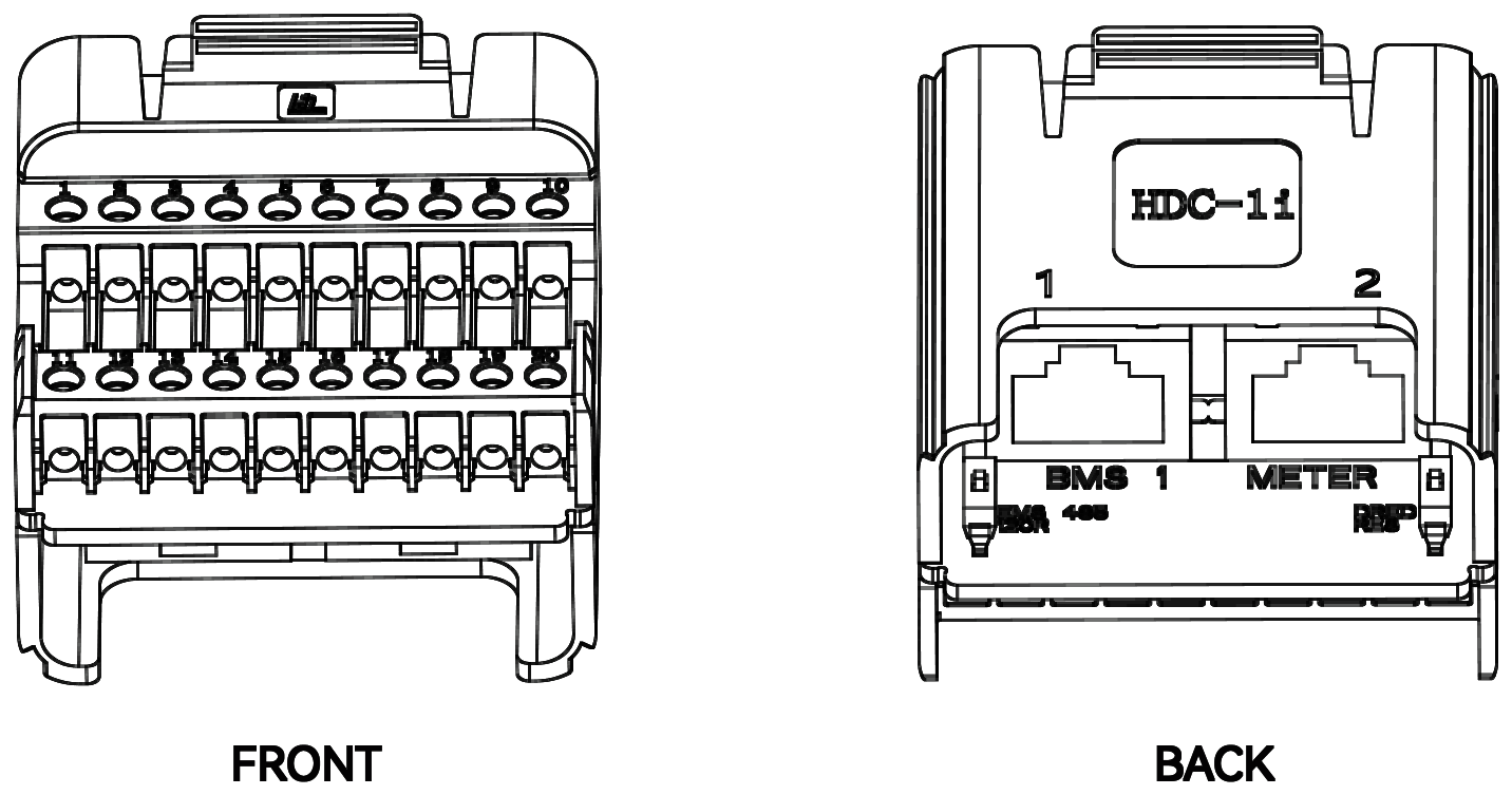
| COM2 pin | Signal | Function |
|---|---|---|
| 1–6 | REF/0, COM/0, D1/5, D2/6, D3/7, D4/8 | DRED connection (Australia and New Zealand) |
| 7, 8 | DO3 NO, COM | Reserved |
| 9, 10 | BK NC, COM | EDA back-up box |
| 11, 12 | DO1 NO, COM | Diesel generator start or smart-load control (optional) |
| 13, 14 | DO2 NO, COM | Reserved |
| 15, 16 | EMS STOP IN+, IN− | Emergency stop (NO or NC, optional) |
| 17, 18 | DI1 IN+, IN− | ATS position input |
| 19, 20 | EMS 485 A, B | External EMS |
| RJ45 | BMS 1 | Battery communication |
| RJ45 | METER | RMM smart meter |
| DIP | EMS 485 120R | EMS termination resistor |
| DIP | DRED RES | 10 kΩ DRED detection resistor. Turn OFF when using DRED |
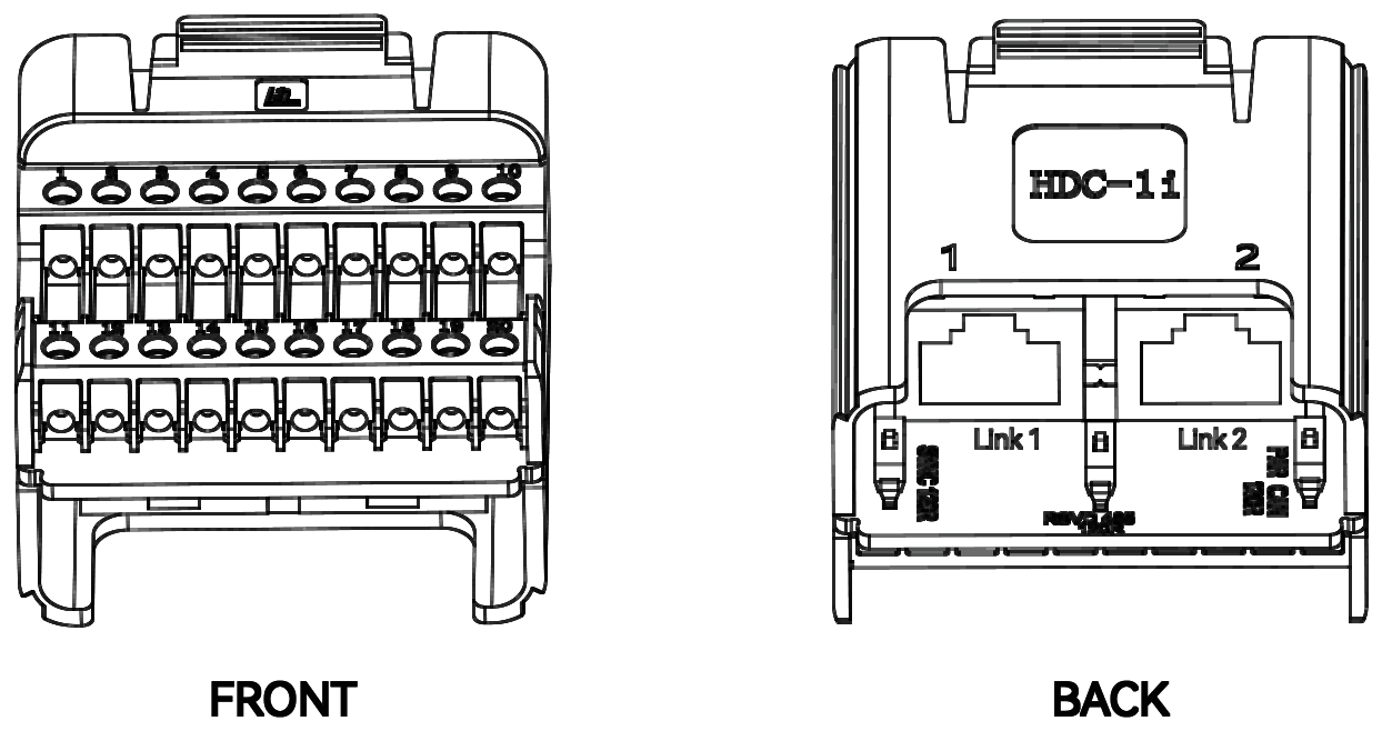
| COM3 pin | Signal | Function |
|---|---|---|
| 1, 2 | DI2 IN+, IN− | Reserved |
| 3, 4 | RSVD 485 A, B | Reserved |
| 5, 6 | CPS 12V+, − | 12 V output |
| 7, 8 | 12V+, − | 12 V output |
| 9, 10 | SVD3, SVD4 | Reserved |
| 11–16 | CT-L1/L2/L3 S1, S2 | Reserved |
| 17, 18 | EV 485 A, B | EV charger |
| 19, 20 | BMS 2 H, L | Reserved |
| RJ45 | Solink/Link 1 and 2 | Parallel communication between inverters, or other devices |
| DIP | SYNC 120R | Parallel sync termination. ON at the first and last inverter only |
| DIP | PAR CAN 120R | Parallel CAN termination. ON at the first and last inverter only |
| DIP | RSVD 485 120R | Reserved |
| RJ45 pin | Colour | BMS 1 | METER | Solink 1 and 2 |
|---|---|---|---|---|
| 1 | White/orange | — | — | Sync+ |
| 2 | Orange | — | — | Sync− |
| 3 | White/green | Encode_B | — | 12V− |
| 4 | Blue | CANH_B | — | CANH_P |
| 5 | White/blue | CANL_B | — | CANL_P |
| 6 | Green | Encode_A | — | 12V− |
| RJ45 pin | Colour | BMS 1 | METER | Solink 1 and 2 |
|---|---|---|---|---|
| 7 | White/brown | CANL_Debug | 485 B2 | 12V+ |
| 8 | Brown | CANH_Debug | 485 A2 | 12V+ |
COM2 and COM3 look alike. COM3 is blue.
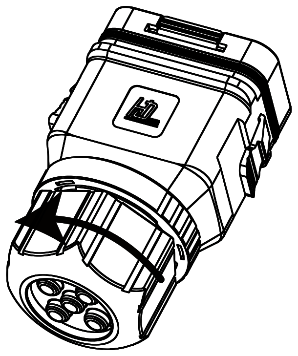
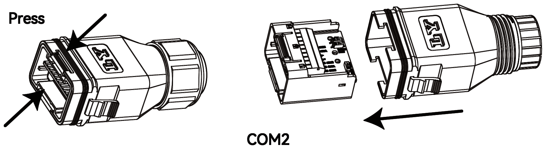
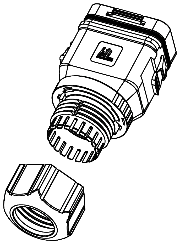
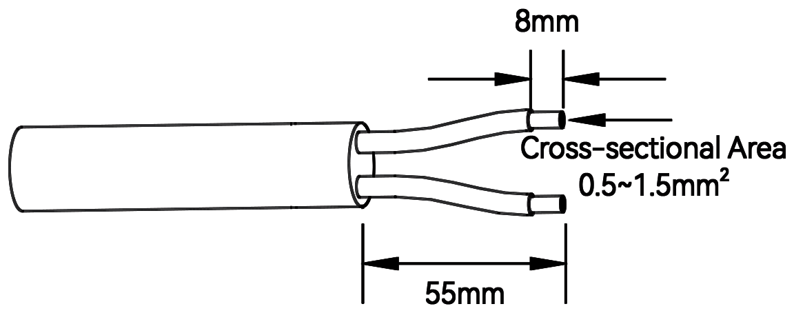
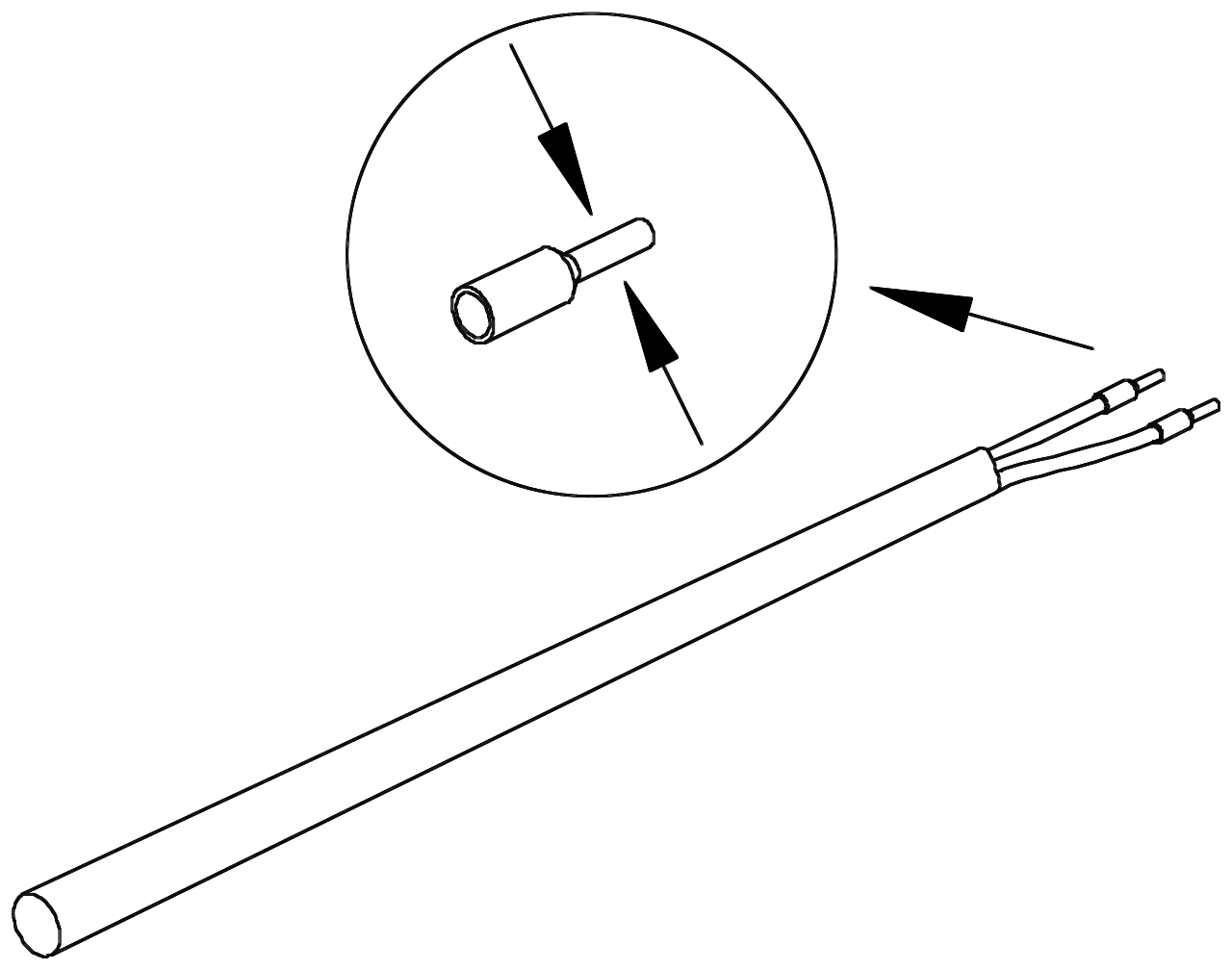
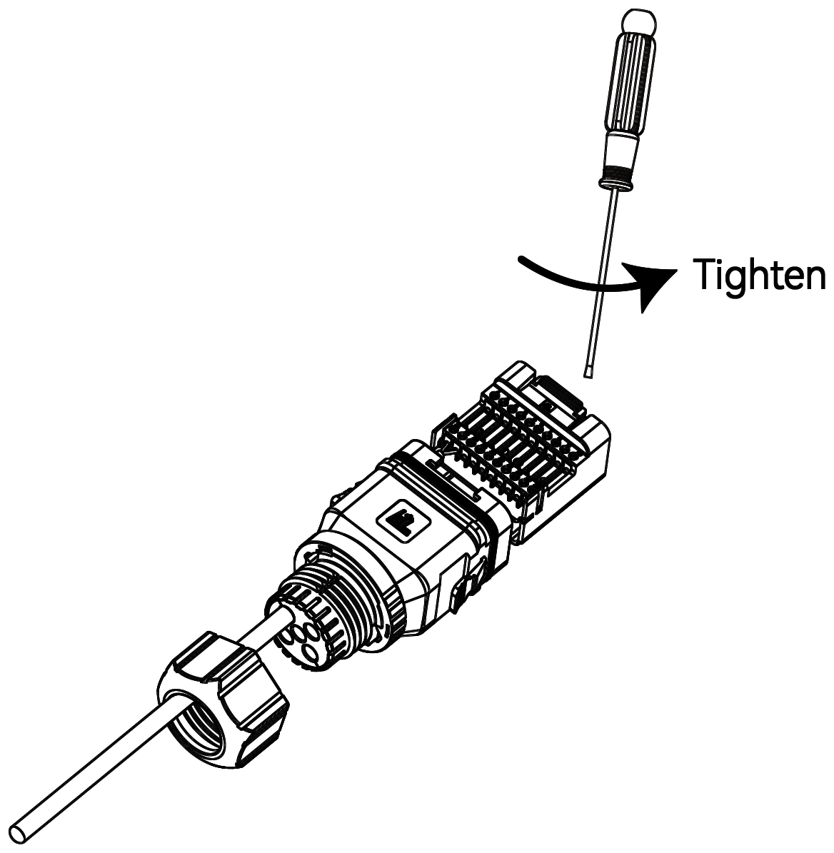
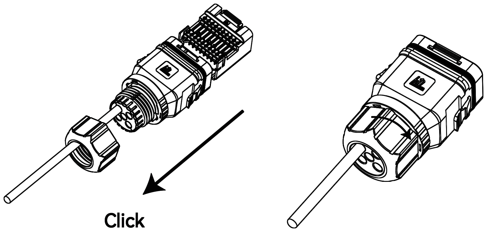
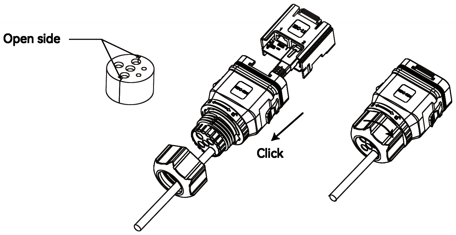
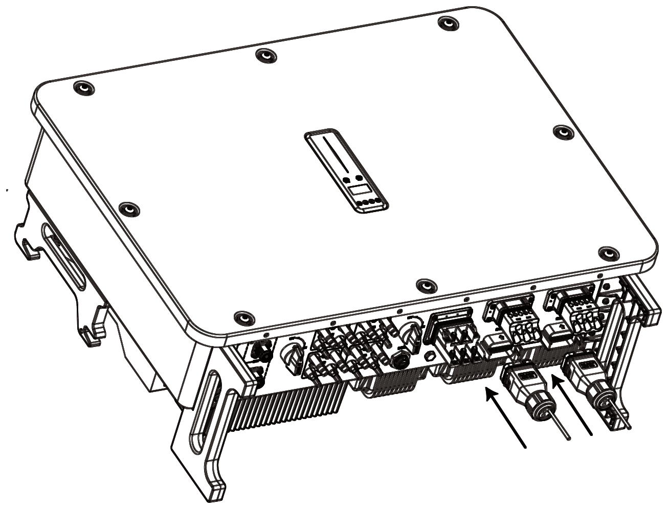
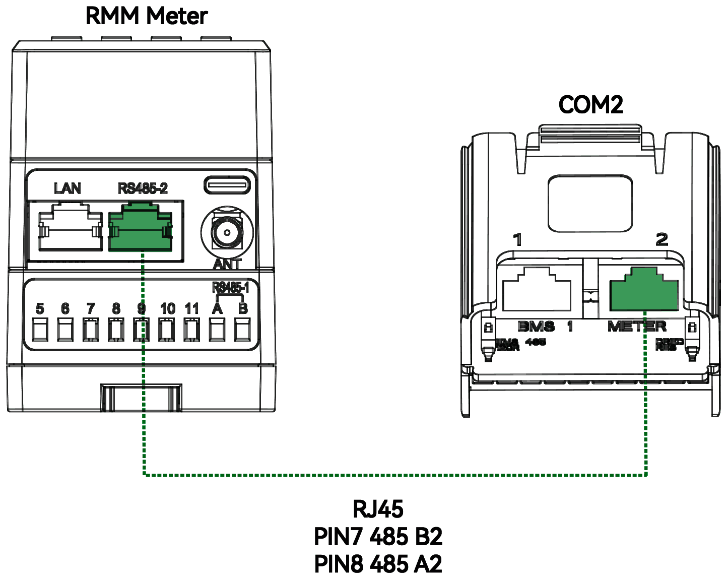
The inverter communicates with the RMM meter over RS485 through the METER RJ45 port (pins 7 and 8). The cable is supplied.
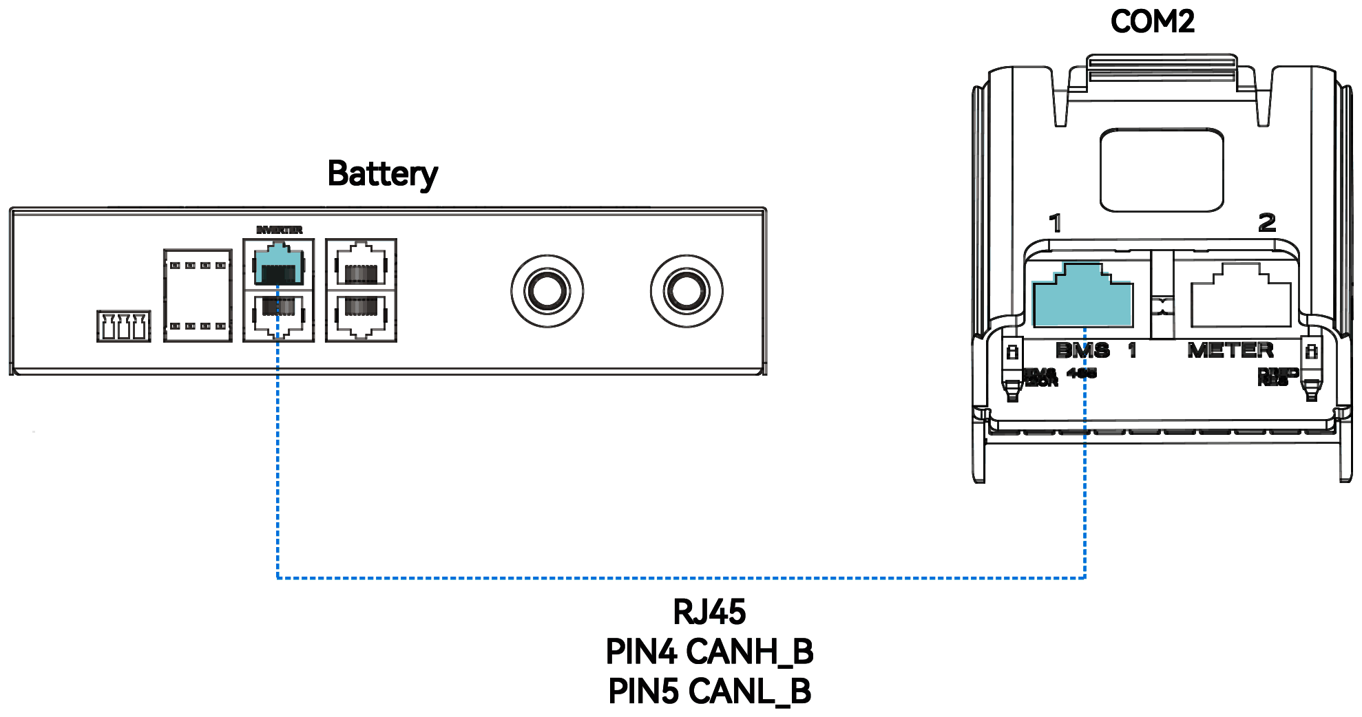
The inverter communicates with the battery BMS over CAN through the BMS 1 RJ45 port (pin 4 CANH, pin 5 CANL). BMS 2 is not used.
Do not earth unused battery communication cores or connect them to other equipment.
The inverter communicates with a Solinteg ECA-series EV charger over RS485 (COM3 pins 17 and 18). Earth the charger properly, or communication will be affected.
The inverter supports the demand response modes of AS/NZS 4777.2 through a demand response enabling device (DRED), connected to COM2 pins 1–6. The DRED is not supplied. DRED and ripple control cannot be used at the same time.
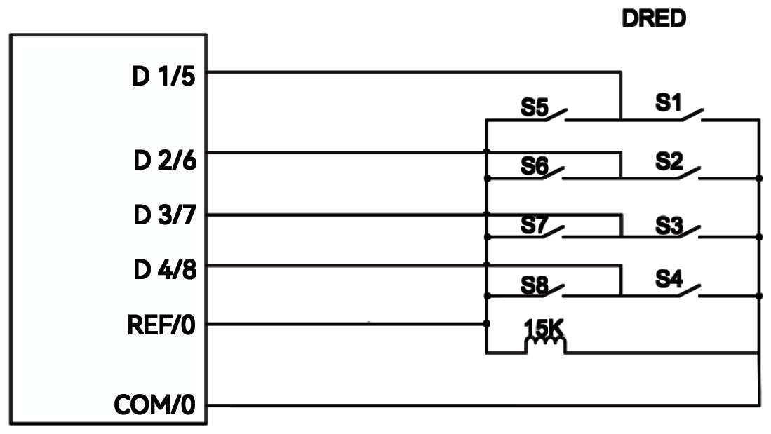
| Mode | Function |
|---|---|
| DRM 0 | Operate the disconnection device |
| DRM 1 | Do not consume power |
| DRM 2 | Do not consume more than 50% of rated power |
| DRM 3 | Do not consume more than 75% of rated power, and source reactive power if capable |
| DRM 4 | Increase power consumption (subject to other active DRMs) |
| DRM 5 | Do not generate power |
| DRM 6 | Do not generate more than 50% of rated power |
| DRM 7 | Do not generate more than 75% of rated power, and sink reactive power if capable |
| DRM 8 | Increase power generation (subject to other active DRMs) |
| Priority | DRM 1 > 2 > 3 > 4; DRM 5 > 6 > 7 > 8 |
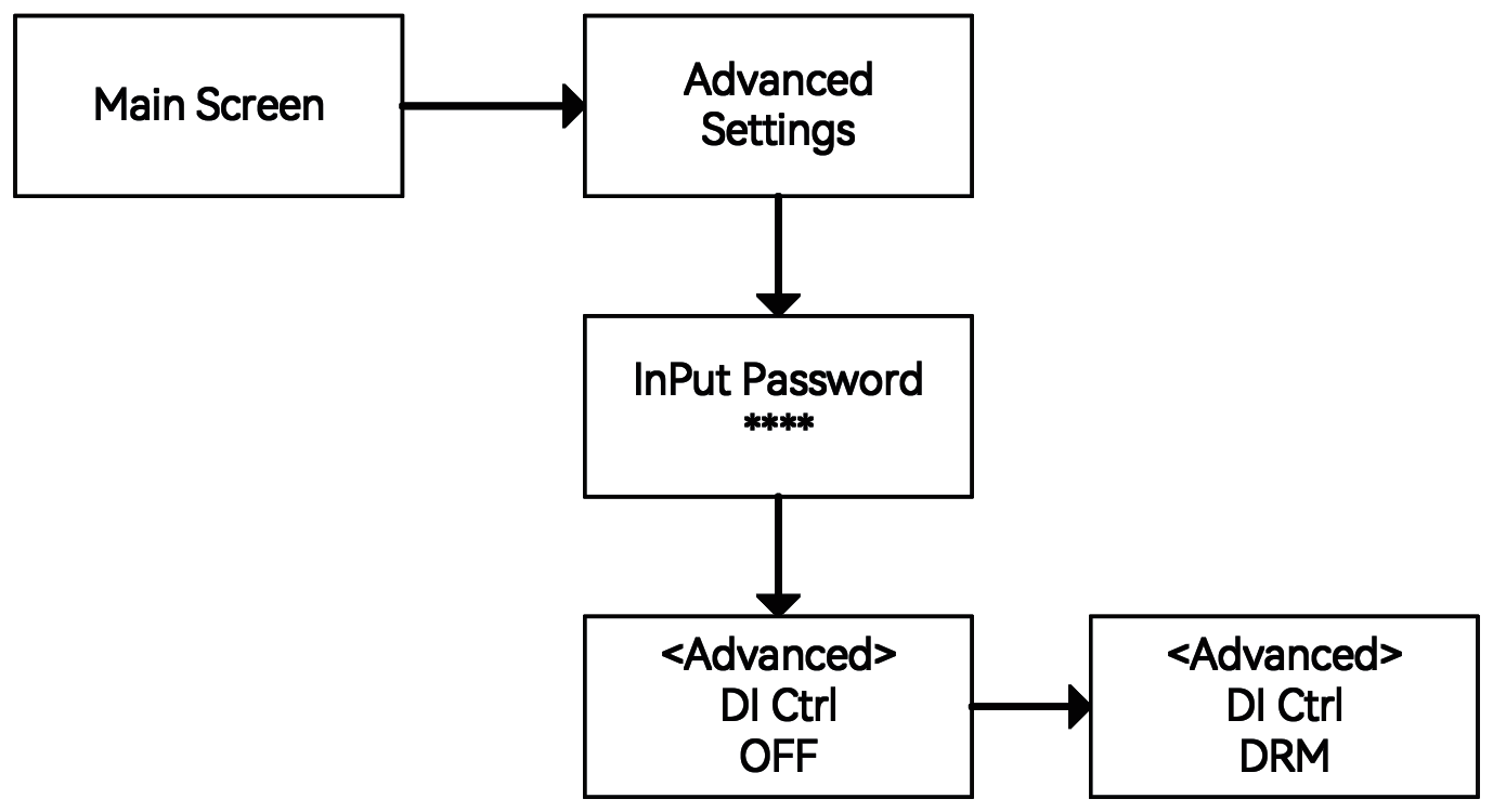
When using DRED, set the DRED RES detection resistor switch to OFF, and set DI Ctrl to DRM (section 7.6). The ripple control (RCR) and German §14a functions described in Solinteg's manual are not used in Australia.
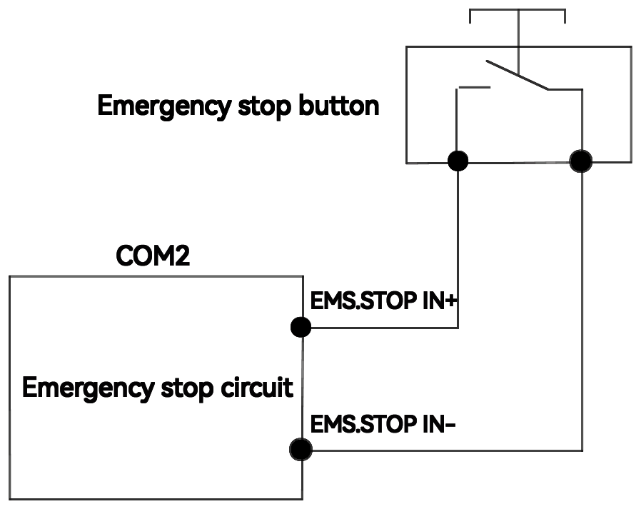
An external emergency stop switch (not supplied) can be connected to COM2 pins 15 and 16. When it operates, the inverter stops its AC output. Set the contact type (NO or NC) on the inverter display.
With Solinteg's additional control device, the inverter can control loads, including SG Ready heat pumps. Contact AERL for details. The DO dry contacts are rated at 30 V DC, 1 A maximum.
See the Solinteg M2HT 25–50 kW Paralleling & Generator Guide, and contact AERL when designing a multi-inverter system.
A parallel system must meet these conditions:
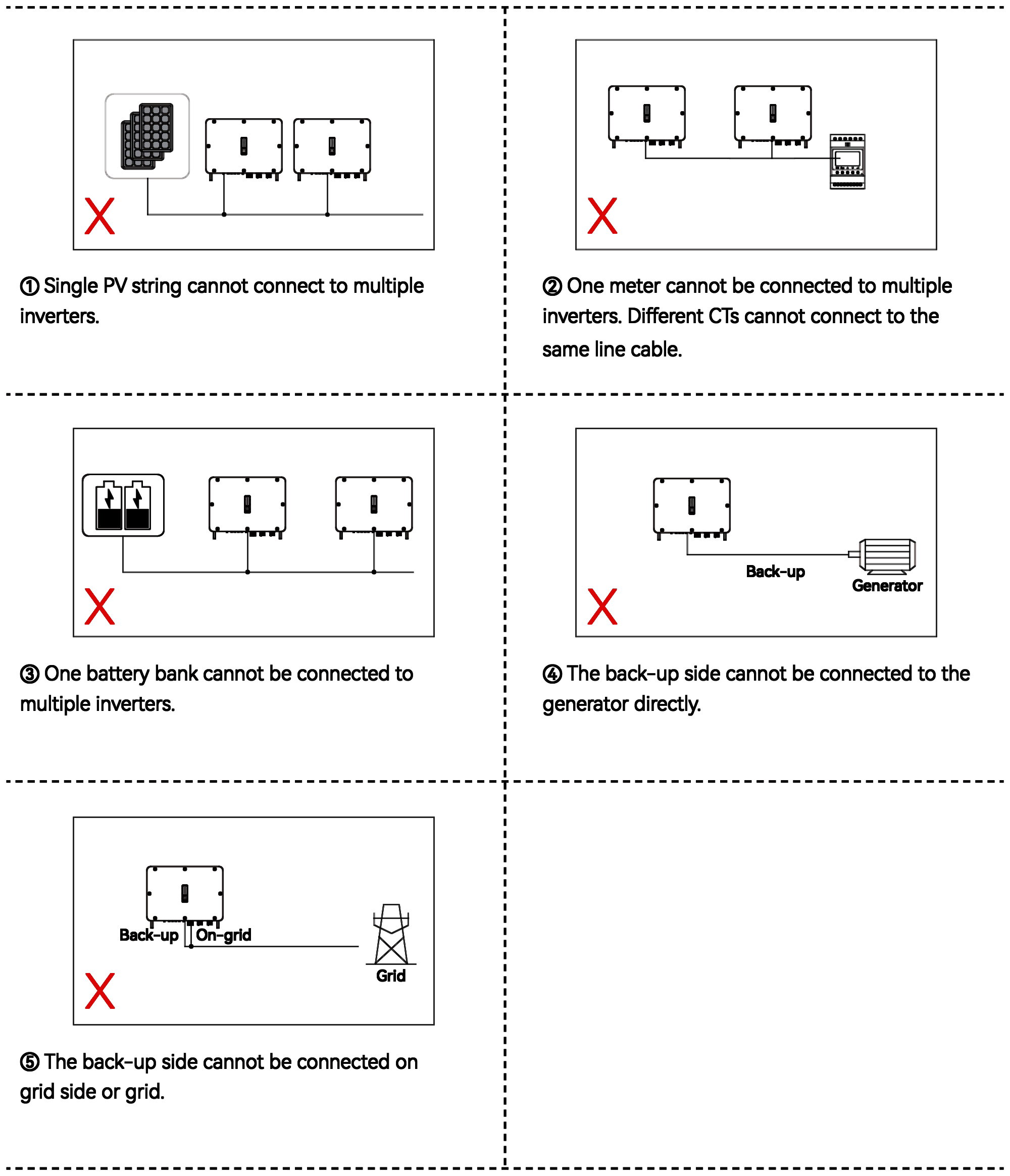
The figure shows what must not be done: one PV string to several inverters; one meter to several inverters, or several CTs on the same conductor; one battery bank to several inverters; the back-up side directly to a generator; or the back-up side to the on-grid side or the grid.
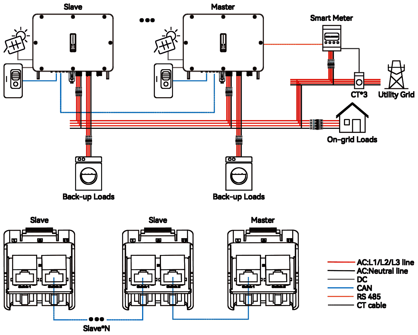
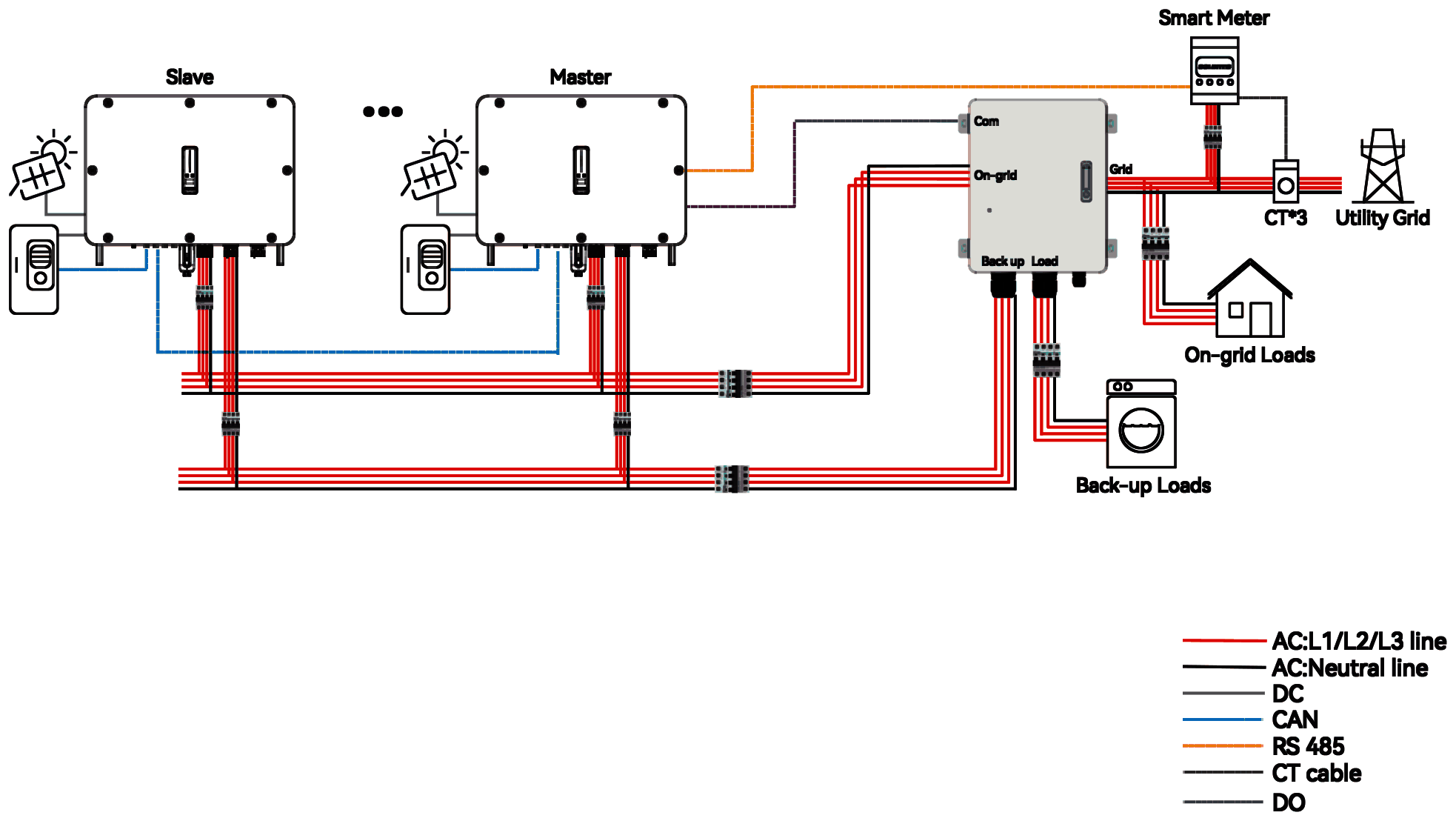
Install the latest Solinteg IntegHub app and register an account, or use the account details from your installer or AERL. The app also configures the inverter locally over Bluetooth.


Web monitoring: www.solinteg-cloud.com
Check the safety code: select the AS/NZS 4777.2 region setting required by your network service provider. Check the battery ID matches the battery fitted.
The inverter can check the CT direction and phase sequence. Run the test from the app once the system is installed.
With SOC Reset on, the inverter charges the battery fully to calibrate its SOC, then turns the function off. We recommend a calibration at commissioning and periodically after that.
To restart, switch on the AC breaker, battery breaker, battery and DC switch, in that order. If the inverter is to be out of service, a licensed electrical worker should disconnect the AC and DC cables.
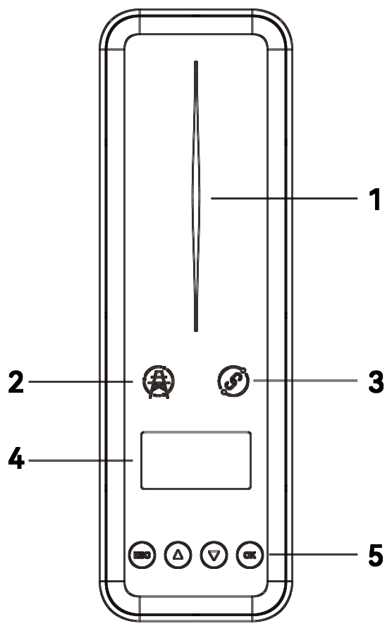
| No. | Indicator | Colour | State | Meaning |
|---|---|---|---|---|
| 1 | Power and alarm | — | Off | No power |
| 1 | Power and alarm | Blue | Fast flashing | Self-test |
| 1 | Power and alarm | Blue | Slow flashing | Waiting |
| 1 | Power and alarm | Blue | Breathing | Operating normally |
| 1 | Power and alarm | Orange | Breathing | Low battery: close to the SOC protection limit |
| 1 | Power and alarm | Red | On | Alarm or fault. Check the display |
| 2 | Grid | — | Off | Grid lost |
| 2 | Grid | — | Slow flashing | Grid detected, not operating on-grid |
| 2 | Grid | — | On | Operating on-grid |
| 3 | Communication | Green | On | Communication normal |
| 3 | Communication | Green | Flashing | Communicating with an EMS or the master inverter |
| No. | Indicator | Colour | State | Meaning |
|---|---|---|---|---|
| 3 | Communication | Orange | On | No communication with the smart meter |
| 3 | Communication | Red | On | No communication with the BMS |
| 4 | Display | — | — | Status and settings. Switches off to save power; press the button to wake it |
| 5 | Button | — | — | Changes the display and sets parameters |
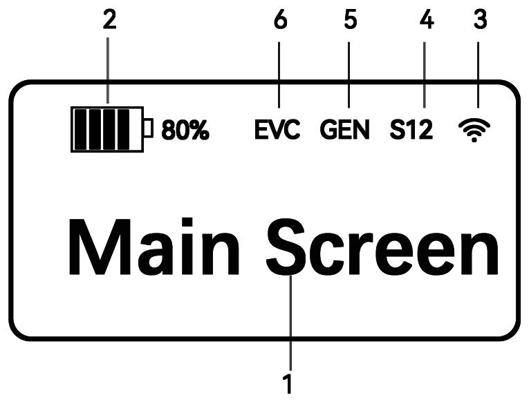
The main screen shows (1) the inverter information, status and settings, (2) battery SOC, (3) the communication method, (4) the status code (section 8.1), (5) generator running and (6) EV charger connected.
| Button | Name | Function |
|---|---|---|
| ESC | Escape | Exit, go back or cancel. Hold for 3 s to restart the display |
| ▲ | Up | Move up or increase a value |
| ▼ | Down | Move down |
| OK | Enter | Open a menu, confirm or edit |
The main screen cycles through the inverter status (Waiting, Checking, On-Grid, Off-Grid, Fault Info, FW Updating), PV values for each MPPT and battery values for each battery input.
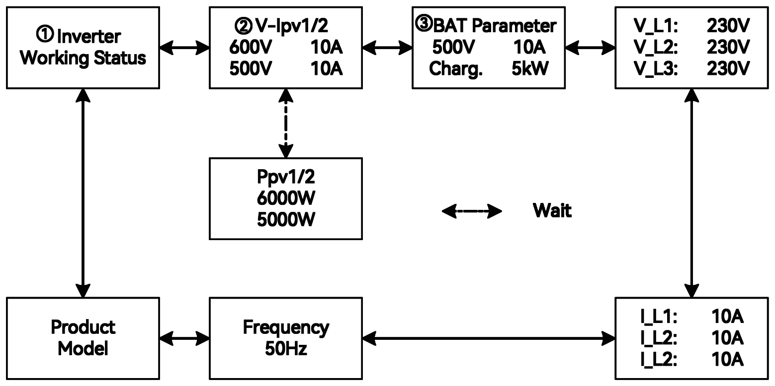
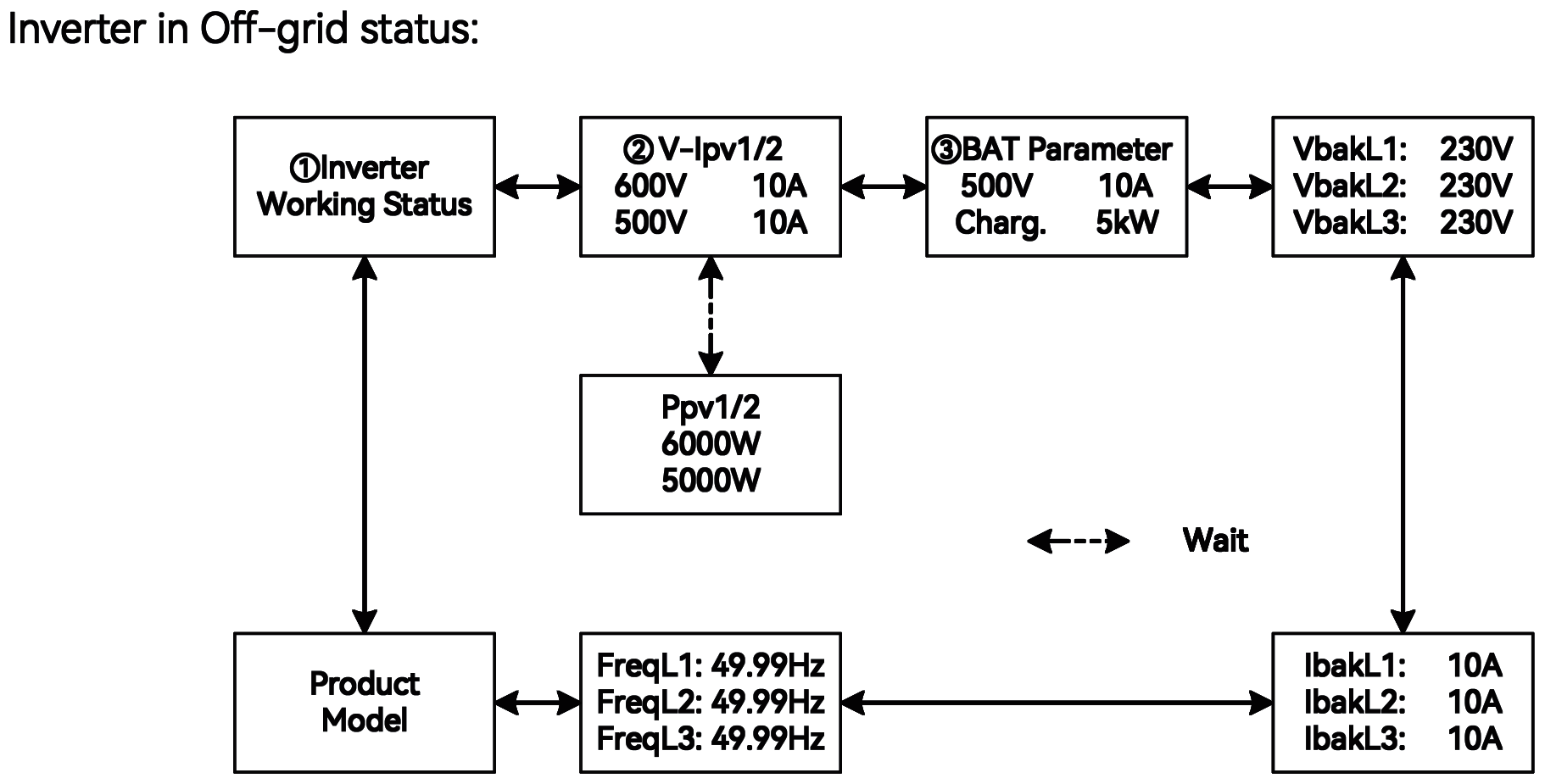
| Item | Description |
|---|---|
| V-Ipv1/2, Ppv1/2 | PV voltage, current and power of each MPPT |
| BAT, Charg., Dischg. | Battery values, charging, discharging |
| V_L1/L2/L3, I_L1/L2/L3, Frequency | Output voltage, current and frequency (on-grid) |
| VbakL1/L2/L3, IbakL1/L2/L3, FreqL1/L2/L3 | Output voltage, current and frequency (off-grid) |
| Fault Info, FW Updating | Fault information, firmware updating |
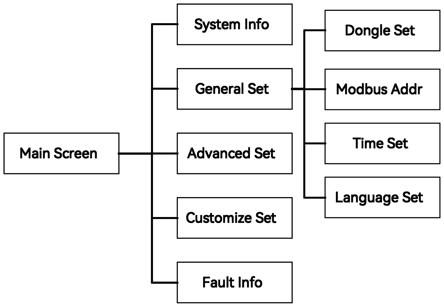
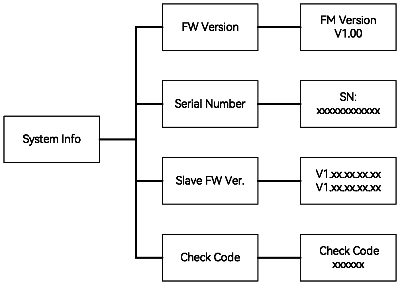
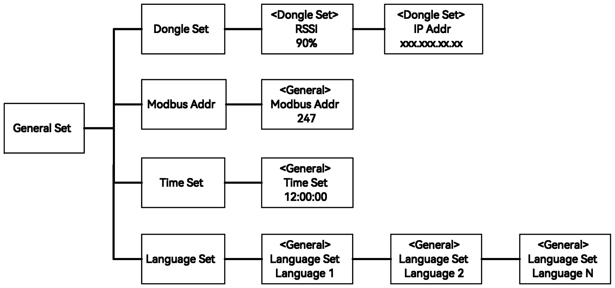
System Info shows the firmware version, serial number, slave firmware versions and check code. General Set shows Wi-Fi signal strength and sets the IP address (LAN, DHCP off), Modbus address, clock and display language. After changing a setting, select Yes to save or No to cancel.
Advanced Set is password protected. Contact AERL support for the password. Its main settings are:
| Setting | Function |
|---|---|
| Safety Set | Safety code. In Australia, the AS/NZS 4777.2 region required by the network service provider |
| Batt_Conn, BAT1/BAT2 Set, BAT2 Sync | Battery inputs: independent or parallel, settings for each, and copying battery 1's settings to battery 2 |
| Battery_ID Set | Battery model. Must match the battery, or BMS communication fails |
| OnGrid SOCProt / EndSOC | On-grid SOC protection and end-of-discharge SOC |
| OffGrid SOCProt / EndSOC | Off-grid SOC protection and end-of-discharge SOC |
| Work Mode | Operation mode (section 2.4) |
| Export Limit, Power to grid | Export limiting on/off, and the export limit |
| ExpLimitDevice, CT Ratio | Meter, CT or no device for export limiting; CT ratio |
| ExpLimit Mode | SingleSeparated limits each phase; Total Phase limits the three-phase total (one or two phases may still export) |
| Export Ctrl | If meter or datalogger communication is lost: Hard stops AC output; Soft limits output to the export setting |
| Reactive Mode, Power Factor, Fixed Q | Reactive power mode and settings (section 7.4) |
| P(U) | Volt-watt response (section 7.5) |
| Setting | Function |
|---|---|
| On-OffGrid SW | Off-grid switching on/off. If off, there is no back-up output when the grid fails. With it on, HVRT and LVRT are disabled |
| Relax OffGrid | Less sensitive on/off-grid switching, for unstable grids |
| Offgrid ReConn | Restart delay after an off-grid overload |
| Import Limit, PowerFromGrid | Grid import limiting on/off, and the import limit |
| Unbalan.Output | Unbalanced three-phase output on/off |
| System Maint. | Restart, stop (bypass kept if enabled), start up, factory reset |
| Phase Sequence | Auto, positive or negative |
| SysBlackStart | Black start on/off |
| Multi-INV Role / No. / Addr | Parallel role (master, slave, independent), number of units (2–10) and slave address (1–9) |
| SOC Reset | SOC calibration charge (section 6.3) |
| MPPT Parallel | Parallel MPPT inputs on/off |
| MaxOutputSet | Rated, Overload (1.1 × rated) or Underload |
| N-PE Check | Back-up N-PE link in off-grid operation (section 5.2) |
| Shadow Scan | MPPT shadow scan on/off |
| DI Ctrl | Off, DRM or RCR (section 7.6) |
| Emergency Stop | Off, NC or NO |
| CommsWatchDog | Slave stops AC output if it loses communication with the master |
| BMS_ISO | Battery insulation check on/off |
| Password Set | Change the password |
Customize Set holds settings for special cases. Change them only on AERL's advice:
| Setting | Function |
|---|---|
| GridRecovB Dly | Delays the back-up output by 500 ms when the grid returns, for non-self-resetting ATSs on both grid and back-up |
| GridRecovChk | Turns off the grid-recovery self-check, for unstable grids where it interrupts the back-up supply |
| Back-upBoxDetc | Monitors the EDA back-up box. Automatic in off-grid parallel; turn on manually for a single inverter with a back-up box |
| GridLostB DlyS / DlyT | Delays the back-up output after grid loss (1–600 s), to help start heavy inrush loads |
| Active Balance | Balances the grid-port phases when there is no PV or battery |
| GFCI Prot | Leakage current protection. Turn off only if safe, with other leakage protection fitted |
| Setting | Function |
|---|---|
| Active Island | Active anti-islanding disturbance (for testing only). Passive islanding protection is unaffected |
| OffGridParPowD | Off-grid parallel power sharing. Must be on for off-grid parallel |
The inverter can regulate reactive power. The modes are enabled through the configuration software, and some are on by default for Australia. Contact AERL to change the defaults.
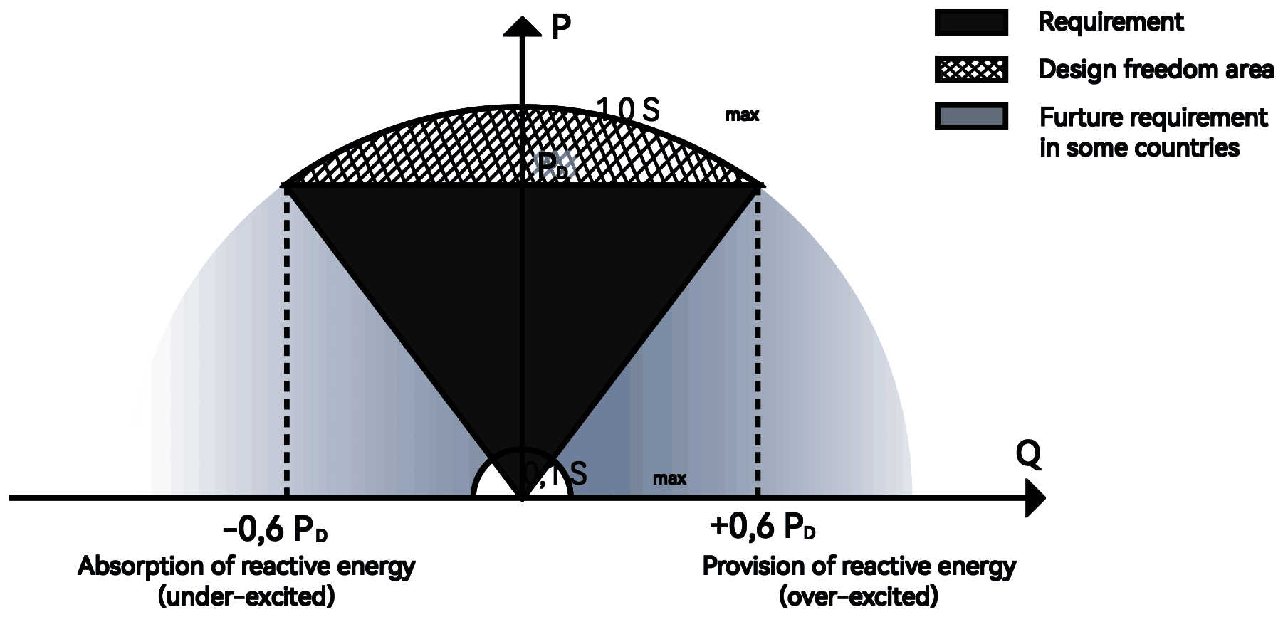
| Mode | Function |
|---|---|
| Off | Power factor fixed at 1.000 |
| PF | Fixed power factor, 0.8 leading to 0.8 lagging (leading: sourcing reactive power; lagging: absorbing) |
| Qt | Fixed reactive power, −60% to +60% of rated power |
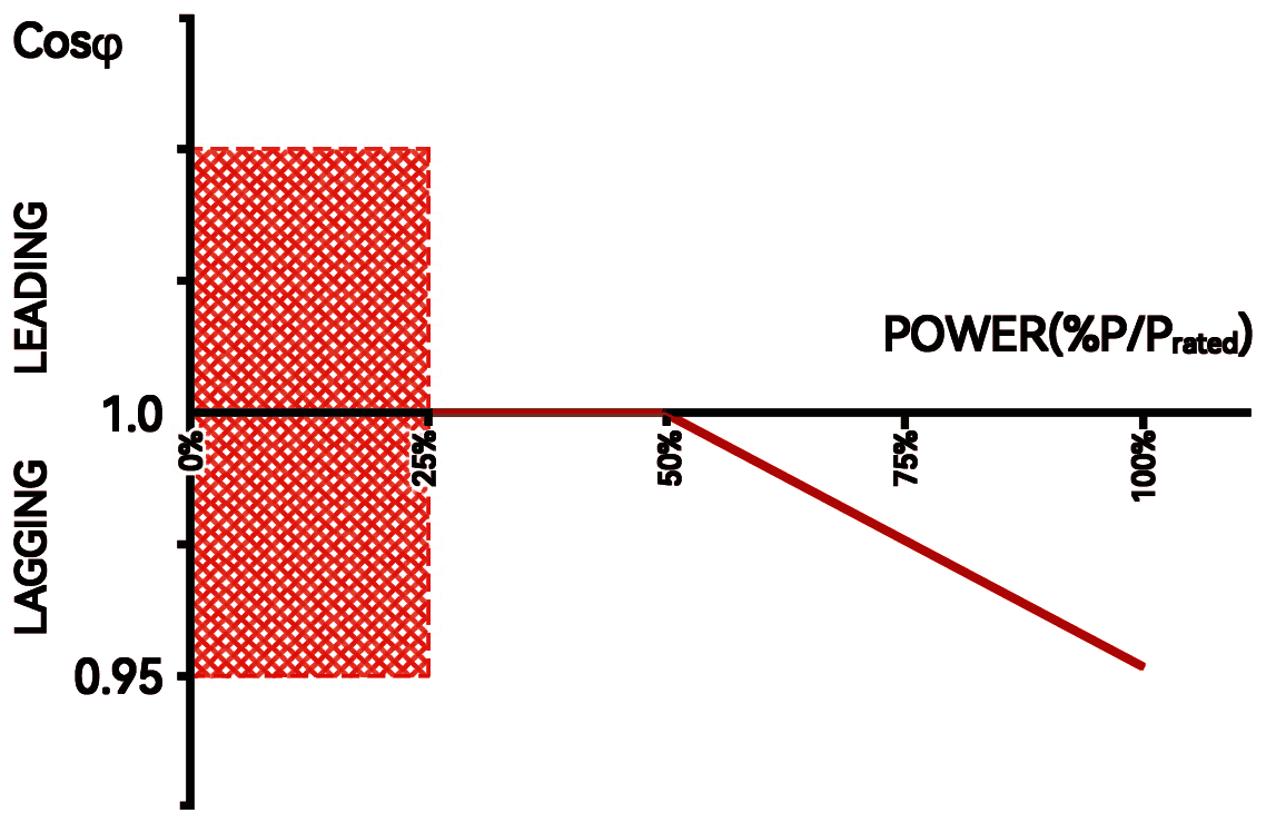
| Cosφ(P) | Power factor varies with output power |
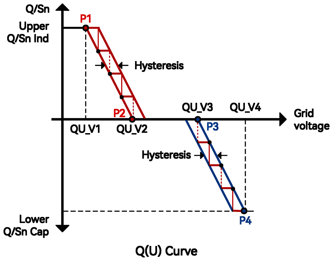
| Q(U) | Reactive power varies with grid voltage (volt-var) |
| Cosφ(P) setting | Description | Range |
|---|---|---|
| P1, P2, P3 | Output power at points A, B and C | 10–100%, 20–100%, 20–100% |
| K1, K2, K3 | Power factor at points A, B and C | 0.8–1 |
| Enter / Exit voltage | Voltage that activates / deactivates the function | 100–110% / 90–100% |
| Q(U) setting | Description | Range |
|---|---|---|
| QU_V1, QU_V2 | Grid voltage at points 1 and 2 | 80–100% |
| QU_V3, QU_V4 | Grid voltage at points 3 and 4 | 100–120% |
| QU_Q1 | Q/Sn at point 1 | 0 to 60% |
| QU_Q2, QU_Q3 | Q/Sn at points 2 and 3 | −60% to 60% |
| QU_Q4 | Q/Sn at point 4 | 0 to −60% |
| Enter / Exit power | Active power that activates / deactivates the function | 20–100% / 1–20% |
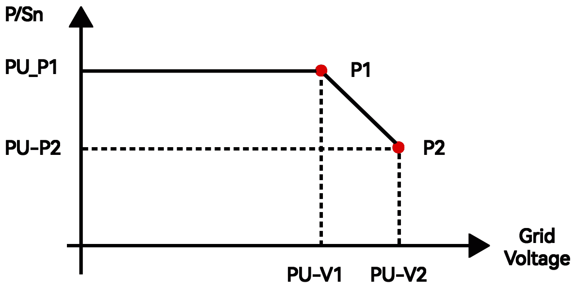
The output power reduces as the grid voltage rises. P(U) is the volt-watt power quality response mode of AS/NZS 4777.2 and is on by default for Australia.
| Setting | Description | Range |
|---|---|---|
| PU_V1, PU_V2 | Grid voltage at points 1 and 2 | 100–120% |
| PU_P1, PU_P2 | P/Sn at points 1 and 2 | 0–100% |
| PU(τ) | Time constant | 0–60 s |
Firmware version: Main Screen → System Info → FW Version.

Grid settings in Solinteg Cloud: you can check and adjust the safety code, protection settings, reactive power modes and P(U) through the monitoring platform.
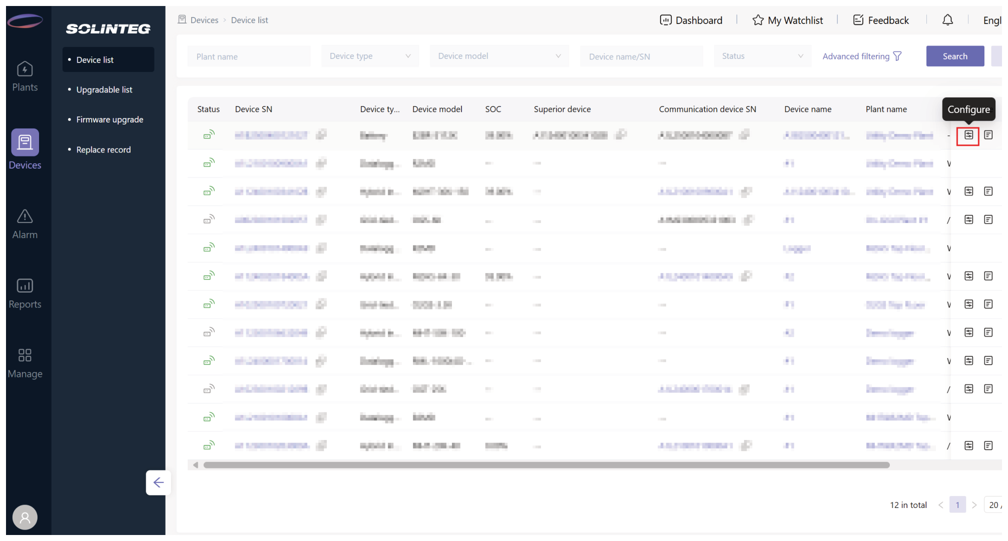
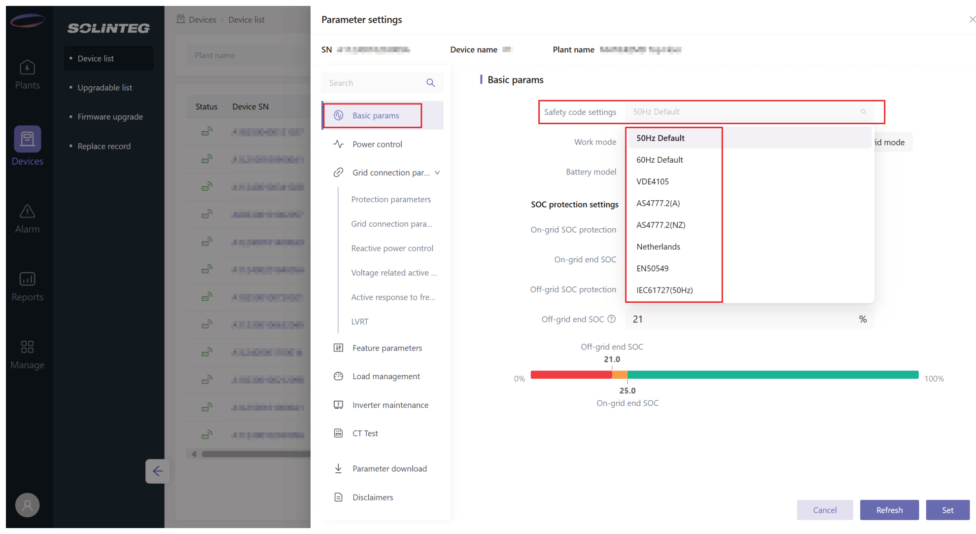
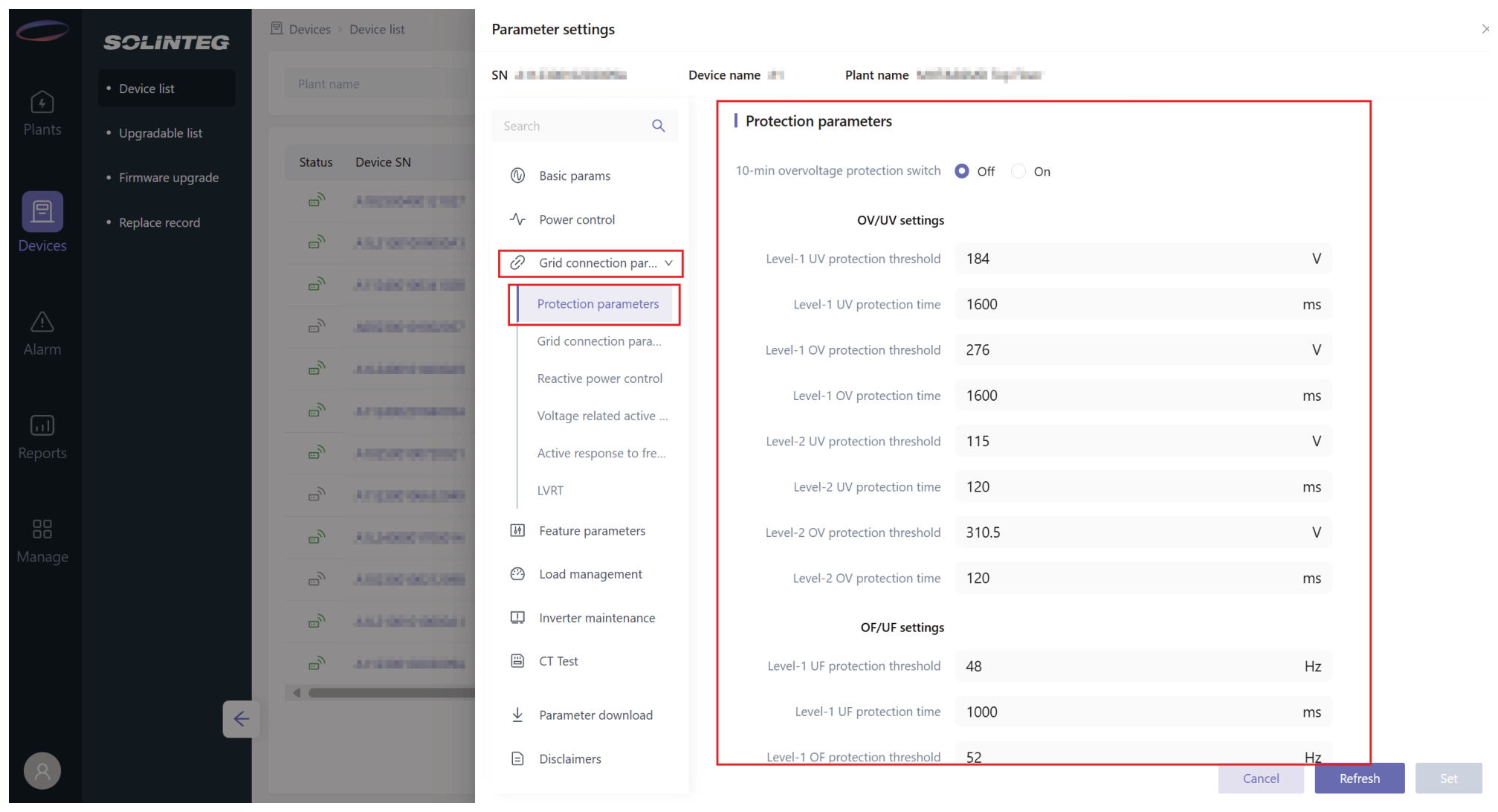
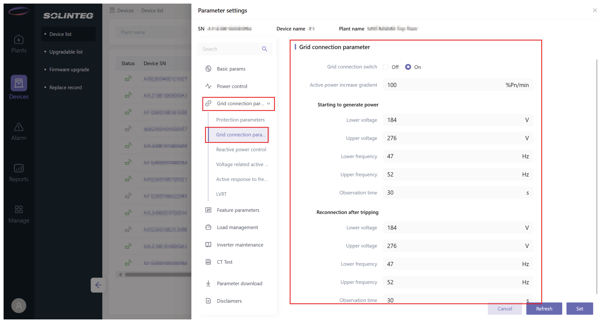
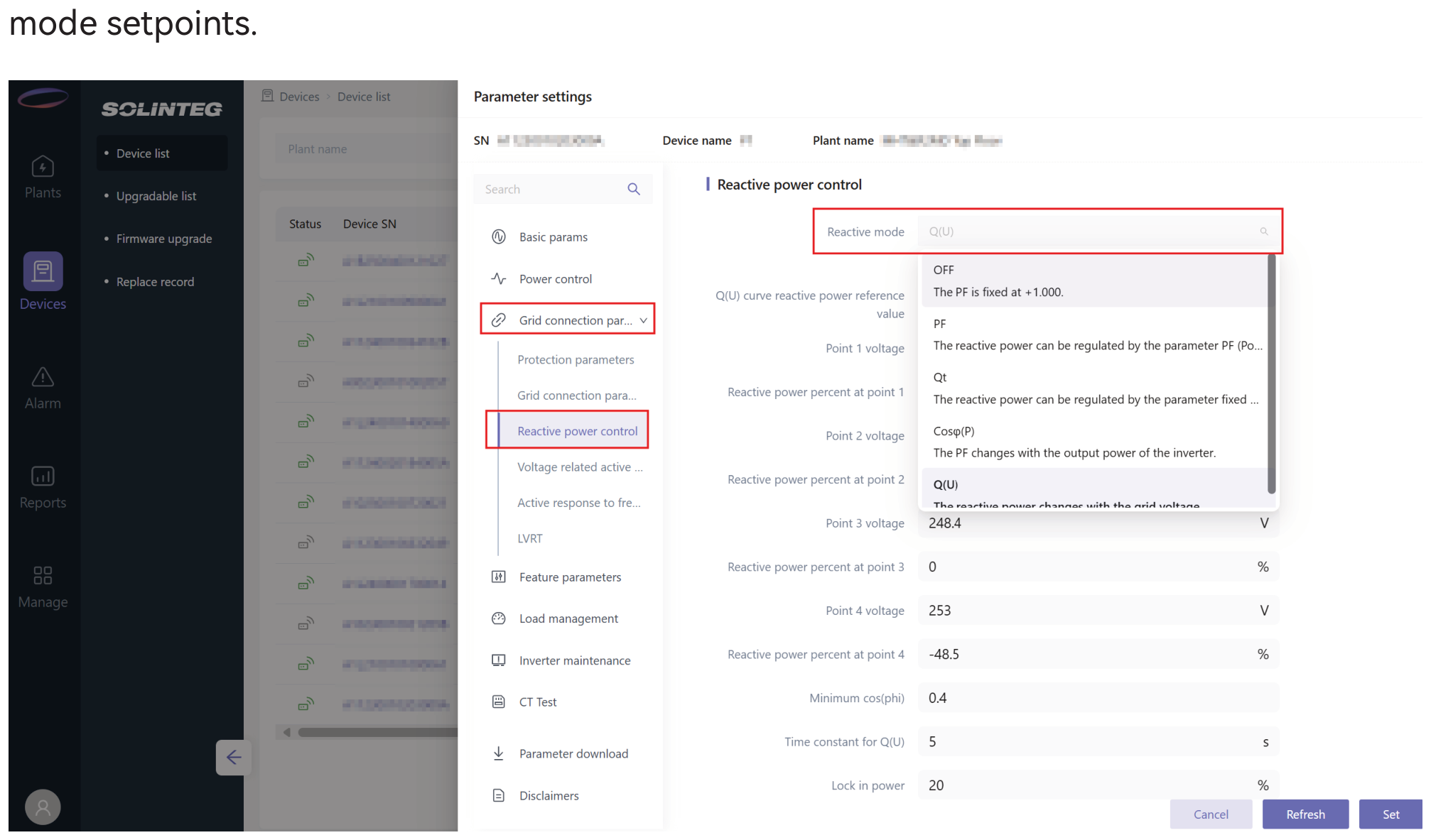
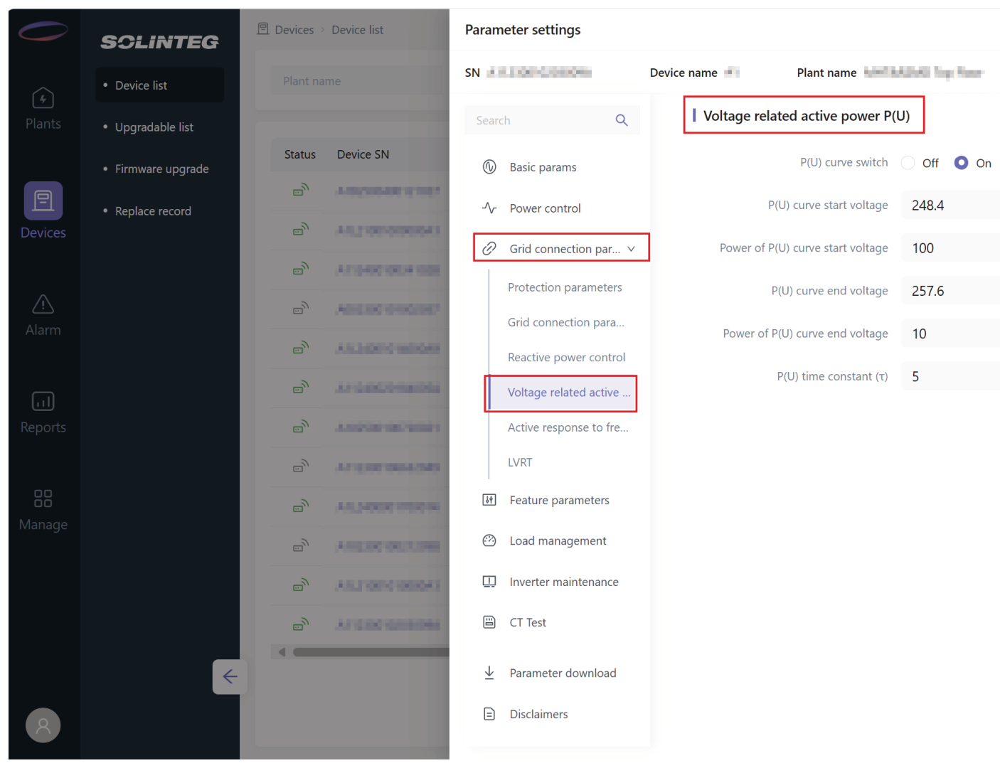
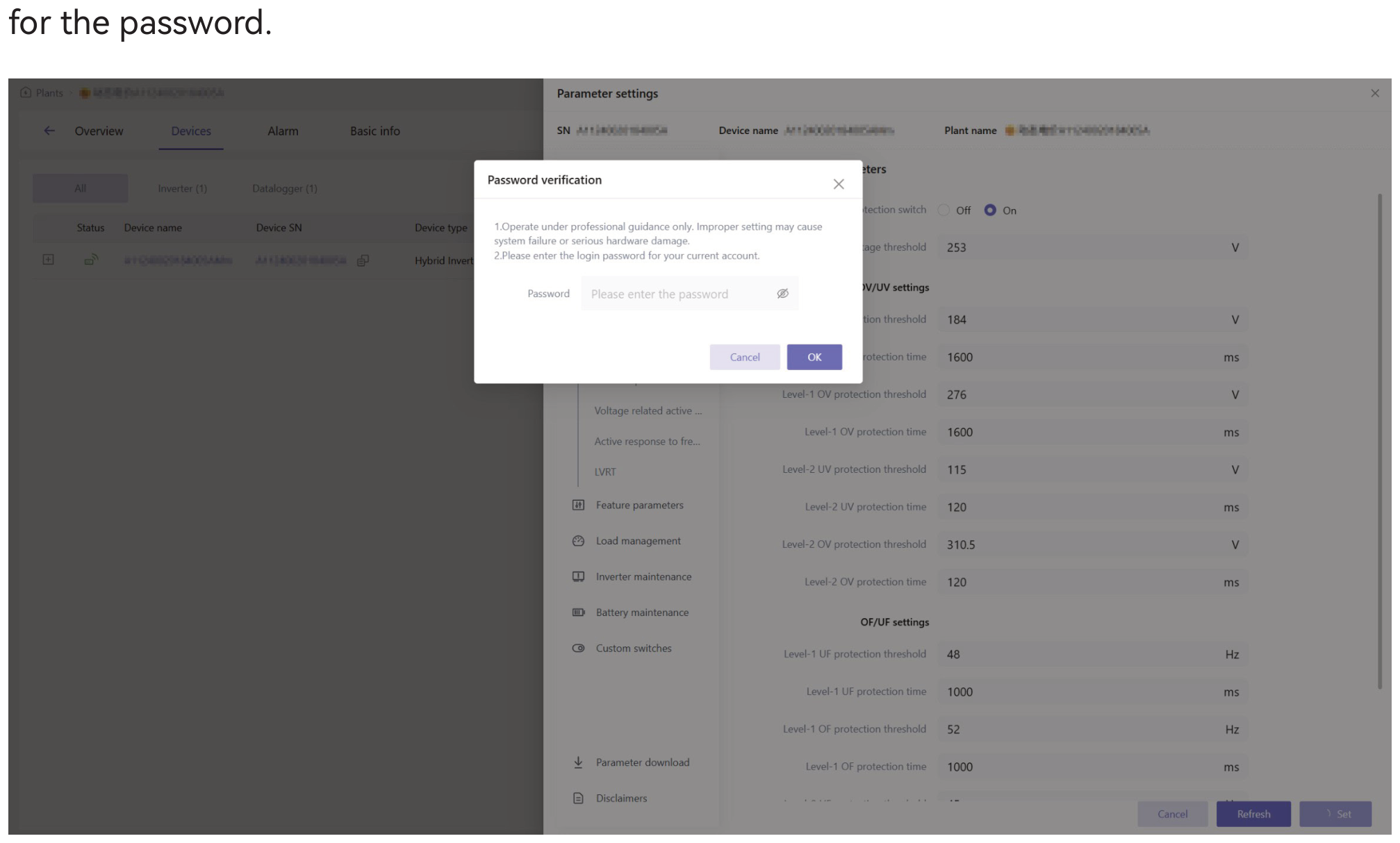
Changing the safety code, protection settings, or reactive or active power modes needs a password. Once set at commissioning, these settings are locked. Contact AERL support for the password.
DRED: on the display, open Advanced Settings, enter the password and set DI Ctrl to DRM.
| Code | Meaning |
|---|---|
| S01 | Work mode not set |
| S02 | Emergency stop active |
| S03 | DC conditions not met |
| S04 | Grid voltage or frequency out of range |
| S05 | Off-grid switch not enabled, off-grid |
| S06 | No battery, off-grid |
| S07 | Stopped by command |
| S08 | SOC low and no PV input |
| S09 | Lost communication with a slave inverter (parallel) |
| S10 | Lost meter communication under hard export control |
| S11 | Waiting for bypass |
| S12 | Updating, standby |
| S13 | Diesel generator fault |
| S15 | Off-grid |
| S16 | Updating, clearing flag |
| S17 | Power limited by command |
| S18 | Power limited: over-frequency |
| S19 | Power limited: over-temperature |
| S20 | Power limited: over-current |
| S21 | Power limited: reactive power |
| S22 | Power limited: export limit |
| S23 | Soft start (slow loading) |
| S24 | Power limited: overvoltage |
| S25 | Power limited: system |
| S26 | Power limited: EMS command |
| S32 | PV power limited |
When a fault occurs, the display shows a message and the inverter may stop exporting. Where the table says to contact support, call AERL on 1800 950 865 or email [email protected].
| Message | Cause | Action |
|---|---|---|
| DC BUS Over Voltage | DC bus voltage above the upper limit | 1. Check whether the DC input voltage is above the limit. 2. Restart the inverter. 3. Contact AERL support. |
| DC BUS Voltage Unbalance | Current oscillation unbalancing the DC bus, or a damaged IGBT | 1. Restart the inverter. 2. Contact AERL support. |
| DC BUS Voltage Low | Back-up load above capacity | 1. Reduce the back-up load. 2. Check the battery's load capacity. |
| AC Current Sensor Fault | Current sensing circuit fault | 1. Restart the inverter. 2. Contact AERL support. |
| E2 Fault | EEPROM fault | 1. Restart the inverter. 2. Contact AERL support. |
| FLASH Fault | Internal storage fault, for example from a strong magnetic field | 1. Restart the inverter. 2. Contact AERL support. |
| SCI Fault | Internal communication (DSP–ARM) failed, for example from a strong magnetic field | 1. Restart the inverter. 2. Contact AERL support. |
| SPI Fault | DSP communication interrupted | 1. Restart the inverter. 2. Contact AERL support. |
| Comm. Sampling Fault | AD sampling interrupted | 1. Restart the inverter. 2. Contact AERL support. |
| Relay Fault | Relay fault | 1. Restart the inverter. 2. Contact AERL support. |
| HW Fault | Unknown hardware fault | 1. Restart the inverter. 2. Contact AERL support. |
| PV Power Low | Not enough PV, or battery output limited | 1. Check the PV wiring. 2. Check the battery status. |
| PV Over Voltage | PV input voltage above the limit | Reduce the number of modules so each string's open-circuit voltage is below the inverter's maximum input voltage. |
| ISO Over Limitation | DC insulation resistance to earth too low | 1. Check the PV modules, cables and connectors for water or damage. 2. Measure the DC insulation resistance with an insulation tester. It must be at least 500 kΩ. 3. Contact AERL support. |
| Message | Cause | Action |
|---|---|---|
| GFCI Fault | Earth leakage current above the limit | 1. Restart the inverter. 2. Check the PV modules, cables and connectors for water or damage. 3. Contact AERL support. |
| GFCI Sensor Fault | Leakage current sensor fault | 1. Restart the inverter. 2. Contact AERL support. |
| DCI Fault | DC injection above the limit | 1. Restart the inverter. 2. Contact AERL support. |
| BAT Voltage Fault | Battery voltage above the limit | 1. Check whether the battery voltage is out of range. 2. Check whether the battery shut down when the fault occurred. |
| BAT Power Low | Abnormal BMS status | Check the battery status. |
| BAT Invalid | No battery connected, or BMS fault | Check the BMS status. |
| BMS Comm Fault | No communication between the inverter and the BMS | 1. Check the battery ID setting. 2. Check the BMS communication connection (BMS 1). 3. Check the battery status. |
| Meter Comm Fault | No communication between the inverter and the meter | 1. Check the meter communication connection. 2. Check the meter is a compatible model. |
| Grid Voltage Fault | Grid voltage outside the safety code limits | 1. Check the safety code. 2. Check the AC wiring. 3. Check for voltage rise from high AC cable impedance; if so, use a larger cable. 4. Widen the voltage limits only with the network service provider's permission. |
| Grid Frequency Fault | Grid frequency outside the safety code limits. Recovers automatically after occasional fluctuations | 1. Check the safety code. 2. Widen the frequency limits only with the network service provider's permission. |
| Mains Lost | Grid outage, or AC breaker or circuit open | 1. Check whether the grid supply is lost. 2. Check the AC wiring and breakers. |
| Phase Lock Fault | Abnormal grid phase sequence, or voltage sampling fault | 1. Check the AC wiring. 2. Contact AERL support. |
| BAK Voltage Fault | Voltage on the back-up output, or back-up relay fault | 1. Check whether the back-up side is connected to a supply. 2. Restart the inverter. |
| Backup Load Fault | Back-up load above capacity | 1. Reduce the back-up load. 2. Check the battery's load capacity. |
| Message | Cause | Action |
|---|---|---|
| Inverter Over Current | Abnormal back-up load in off-grid operation | 1. Check for inrush or excessive back-up load. 2. Check the back-up side for a short circuit. |
| Inverter Over Voltage | Back-up voltage above the limit off-grid, or internal fault | 1. Check for inrush or excessive back-up load. 2. Check the back-up side for a short circuit. |
| N-PE Check Fault | Back-up earth loose or poorly connected | 1. Check the earth wiring. 2. If the N-PE link is not needed, turn N-PE Check off. |
| Over Temperature | Internal temperature too high | 1. Check that the location is well ventilated. 2. Switch the inverter off to cool, then restart it. 3. Contact AERL support. |
| Internal Fan Fault | Internal fan fault or low supply | 1. Restart the inverter. 2. Contact AERL support. |
| External Fan Fault | External fan broken, blocked or low supply | Check the fan for obstructions and clean it if needed. If the fault persists, contact AERL support. |
Keep unauthorised people away, with a temporary sign or barrier, during electrical work and maintenance. In bypass, the grid supplies the loads directly. Do not work on the DC side in bypass: stop the inverter and turn the DC switch off first.
Do not replace internal components. Contact AERL for service.
| Item | Check | Interval |
|---|---|---|
| Cleaning | Dust or debris on the heat sink and air inlets and outlets | 6–12 months |
| Electrical connections | Cables are securely connected | 6–12 months |
| Seals | All terminals and ports are sealed. Reseal any cable entry that is ageing or unsealed | Yearly |
Battery installation and maintenance must be done or supervised by people competent with batteries. Follow the battery supplier's instructions.
Never put a battery in a fire: it may explode. Never open or break a battery: the electrolyte is harmful. Remove metal items, use insulated tools, and switch off the battery DC breaker before connecting or disconnecting battery terminals. If the battery is unintentionally earthed, remove the earth connection before working on it.
If the PV array develops an earth fault, the inverter alarms until the fault is cleared, as AS/NZS 5033 requires:
Install the inverter where the alarm indicator will be noticed, or set up email alerts.
Yes, while the grid is present. No, when the grid is down: off-grid operation needs a battery.
Yes, provided a battery is connected.
No. Only high-voltage lithium (LFP) batteries compatible with the M2HT 25–50K can be connected.
Yes. Each PV string input accepts up to 20 A, so modules of 18 A or more can be used.
On-grid, set MaxOutputSet to Overload for 1.1 × rated output. Off-grid, the back-up peak output is 1.5 × rated output for 10 seconds.
| Model | 25K | 29.9K | 30K | 40K | 50K |
|---|---|---|---|---|---|
| MPPT voltage range at rated power (V) | 200–850 | 200–850 | 200–850 | 265–850 | 330–850 |
| Rated / max. output power, on-grid and back-up (kW) | 25.0 | 29.9 | 30.0 | 40.0 | 50.0 |
| Rated / max. apparent power (kVA) | 25.0 | 29.9 | 30.0 | 40.0 | 50.0 |
| Rated output current at 220 / 230 V (A) | 37.9 / 36.2 | 45.3 / 43.3 | 45.5 / 43.5 | 60.6 / 58.0 | 75.8 / 72.5 |
| Max. output current (A) | 37.9 | 45.3 | 45.5 | 60.6 | 75.8 |
| Max. battery charging power from grid (kW) | 25.0 | 30.0 | 30.0 | 40.0 | 50.0 |
| Max. grid input apparent power** (kVA) | 50.0 | 60.0 | 60.0 | 80.0 | 80.0 |
| Max. grid input current (A) | 75.8 | 90.9 | 90.9 | 121.2 | 121.2 |
| Generator: max. input apparent power (kVA) | 30.0 | 36.0 | 36.0 | 48.0 | 60.0 |
| Generator: max. input current (A) | 45.5 | 54.5 | 54.5 | 72.7 | 90.9 |
Model names are M2HT-xxK-150.
| Parameter | Value |
|---|---|
| PV input | |
| Start-up voltage | 135 V |
| Max. PV input voltage | 1000 V* |
| Rated PV input voltage | 620 V |
| Operating voltage range | 200–950 V* |
| MPPTs × inputs per MPPT | 4 × 2 |
| Max. input current per MPPT | 40 A |
| Max. short-circuit current per MPPT | 50 A |
| Parameter | Value |
|---|---|
| Backfeed current to the array | 0 A |
| Battery | |
| Battery type | Lithium (LFP) with BMS |
| Communication | CAN |
| Voltage range | 150–840 V |
| Max. charge / discharge current | 150 A |
| Short-circuit current rating, battery input | 350 A |
| AC | |
| Rated voltage | 3L/N/PE, 220/380 V or 230/400 V |
| Rated frequency | 50/60 Hz |
| Power factor | 0.8 leading to 0.8 lagging |
| Current THD | < 3% at rated power |
| DC injection | < 0.5% In |
| Back-up peak output | 1.5 × rated power, 10 s |
| On/off-grid switching time | < 10 ms |
| Back-up voltage THD | < 3% (linear load) |
| Efficiency | |
| MPPT efficiency | 99.9% |
| Max. efficiency | 97.8% |
| European efficiency | 97.4% |
| Protection | |
| Integrated | DC reverse polarity, battery reverse connection, insulation resistance, surge (DC and AC type II), over-temperature, residual current, islanding, AC overvoltage, overload, AC short circuit |
| General | |
| Overvoltage category | II (PV, battery), III (mains) |
| Dimensions (W × H × D) | 919 × 739 × 305 mm |
| Weight | 89 kg |
| Ingress protection / protective class | IP66 / class I |
| Parameter | Value |
|---|---|
| Standby consumption | < 40 W |
| Topology | Transformerless |
| Operating temperature | −30 to 60 °C |
| Relative humidity | 0–100% |
| Max. altitude | 3000 m |
| Cooling / noise | Smart fan / < 65 dB |
| Display / communication | OLED and LED / CAN, RS485 |
* Maximum operating PV voltage is 950 V. Between 950 V and 1000 V the inverter stops operating. Above 1000 V the inverter will be damaged.
** Maximum power imported from the grid to supply the back-up loads and charge the battery.
Contact AERL for help with installation, commissioning, settings passwords, faults, firmware, warranty and spare parts for the M2HT 25–50 kW in Australia.
When you contact AERL, have the following ready:
Australian Energy Research Laboratories
1/75 Bluestone Circuit
Seventeen Mile Rocks QLD 4073
Australia