 Download PDF· Rev 1.0.0
Installation and Operating Manual
Tanami HV
Installation and Operating Manual
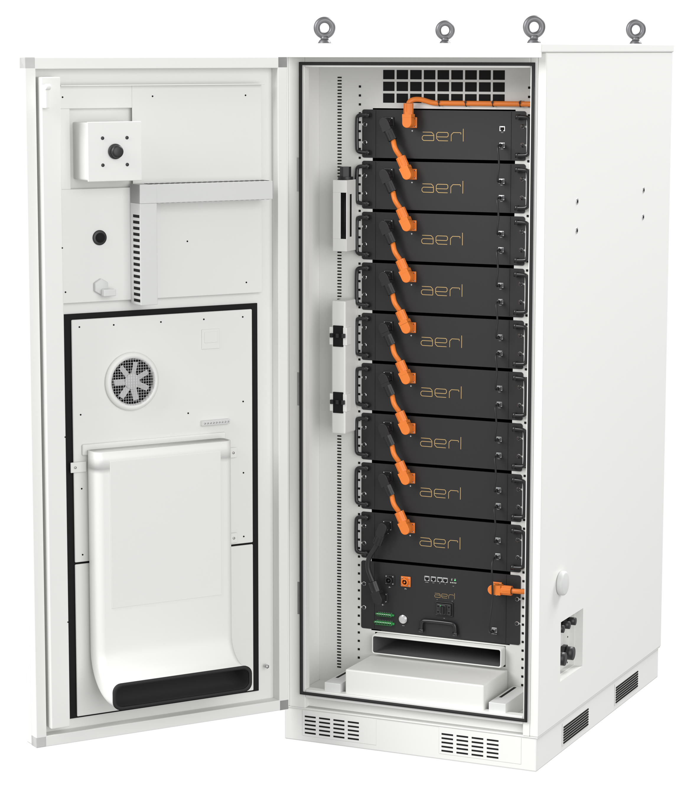
Tanami-HV
Installation and Operating ManualRev 1.0.0, 16 Nov 2026
Download PDF· Rev 1.0.0
Installation and Operating Manual
Installation and Operating Manual
The Tanami HV is a high-voltage lithium iron phosphate (LFP) battery for commercial and industrial energy storage. A Tanami system is one power distribution unit (Tanami-PDU) and six to nine 8.06 kWh battery modules (Tanami-M8.06) connected in series, for 48.38–72.58 kWh at 460.8–691.2 V DC nominal. It connects to a high-voltage hybrid or battery inverter, or to an energy management system (EMS), over CAN, RS485, Modbus RTU or Modbus TCP.
The PDU holds the battery management system (BMS), the DC circuit breaker, the ON/OFF button and the status LEDs. It also has control connections for an air-conditioner, an emergency stop and fire suppression, two dry-contact outputs, and a parallel link that connects up to 16 systems.
The system is supplied in one of two enclosures:
The battery charges at temperatures down to −10 °C and discharges down to −20 °C. It can black-start an off-grid inverter.
This manual covers the installation, commissioning, operation and maintenance of the Tanami system in both enclosures. Where a step differs between the indoor rack and the outdoor cabinet, the manual says so.

A Tanami system operates at up to 788 V DC. Only licensed electrical workers trained in high-voltage DC battery systems may install, commission, maintain or service it.
| Term | Meaning |
|---|---|
| BMS | Battery Management System |
| EMS | Energy Management System |
| HVAC | Heating, Ventilation and Air-Conditioning |
| LFP | Lithium Iron Phosphate (LiFePO4) |
| MCB | Miniature Circuit Breaker (here: the PDU's DC breaker) |
| PDU | Power Distribution Unit: the Tanami's high-voltage control box, with the BMS |
| PE | Protective Earth |
| SOC | State of Charge |
Follow the safety requirements in this manual when installing, commissioning, operating and maintaining the product. Incorrect operation or handling can damage the product and other property, or cause injury or death to the operator or others.
When securing the product with screws or other fasteners, use the correct tools and tighten to the torque given in this manual or on the product label. Incorrect torque can make the product unstable or damage it.
Make sure you know how to use each tool correctly before you start, to prevent injury.
Read this manual in full before installation, so that the product is installed and used safely and correctly.
Ship battery modules in their original packaging, horizontal and firmly fastened to a pallet, with the terminals covered. Batteries are shipped at a reduced SOC to comply with transport regulations.
Move the outdoor cabinet only with a forklift through the forklift pockets in its base, or with a crane on its four lifting eyes. Ship and move the cabinet without modules installed; empty, it weighs about 450 kg.
Stop using a damaged battery immediately, and dispose of it safely or return it to AERL. A damaged battery can leak electrolyte, which may cause breathing difficulties, skin irritation and chemical burns. If you come into contact with electrolyte:
A battery fire may occur if the battery is too close to a flame or the ambient temperature is unusually high. A burning battery may release carbon monoxide, carbon dioxide and other gases, and smoke. The outdoor cabinet has an overpressure relief valve on each side; keep clear of them.
If the battery has been submerged in water, stop using it immediately and contact AERL. If you must disconnect power, or you are in the same water as the battery, first put on rubber gloves and boots to protect yourself from electric shock.
A Tanami system has three parts:
| Part | Part number | Description |
|---|---|---|
| Battery module | Tanami-M8.06 | 8.06 kWh, 76.8 V DC LFP module. Six to nine per system, connected in series. |
| Power distribution unit | Tanami-PDU | BMS, DC circuit breaker and system connections. One per system. |
| Enclosure | Tanami-RACK9 or Tanami-CAB9-OUTD | Indoor rack (6–9 modules) or outdoor cabinet (9 modules). |
Each battery module is packed with:
| Item | Quantity |
|---|---|
| Tanami-M8.06 battery module | 1 |
| Communication cable A (module to module) | 1 |
| Battery cable A (module to module, black to orange) | 1 |
Each PDU is packed with:
| Item | Quantity |
|---|---|
| Tanami-PDU | 1 |
| Battery cable B (module next to the PDU, − to PDU B−) | 1 |
| Battery cable C (last module in the string, + to PDU B+) | 1 |
| Communication cable B (PDU to first module) | 1 |
| Termination resistor, blue (last module COM 1) | 1 |
| Termination resistor, black (PDU OUT) | 1 |
| Screws (modules and PDU into the enclosure) | 40 |
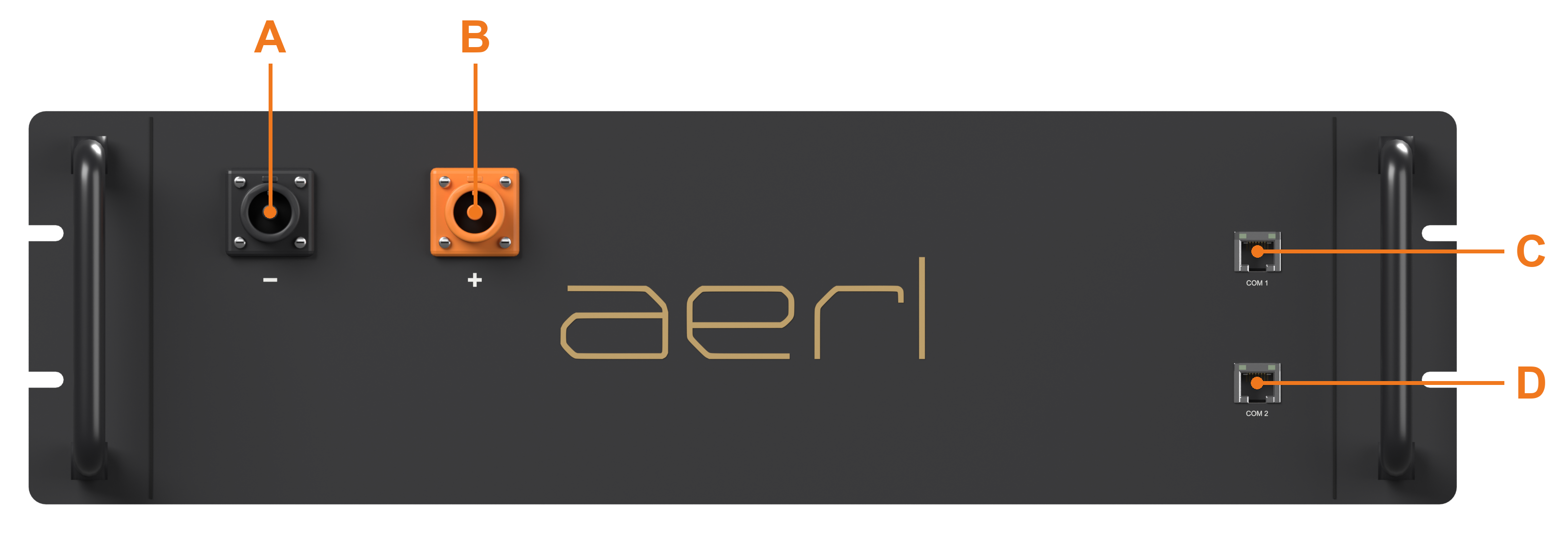
| Position | Label | Function |
|---|---|---|
| A | − | Battery negative |
| B | + | Battery positive |
| C | COM 1 | Communication port (to the next module along the chain, or the blue termination resistor) |
| D | COM 2 | Communication port (from the PDU or the previous module in the chain) |
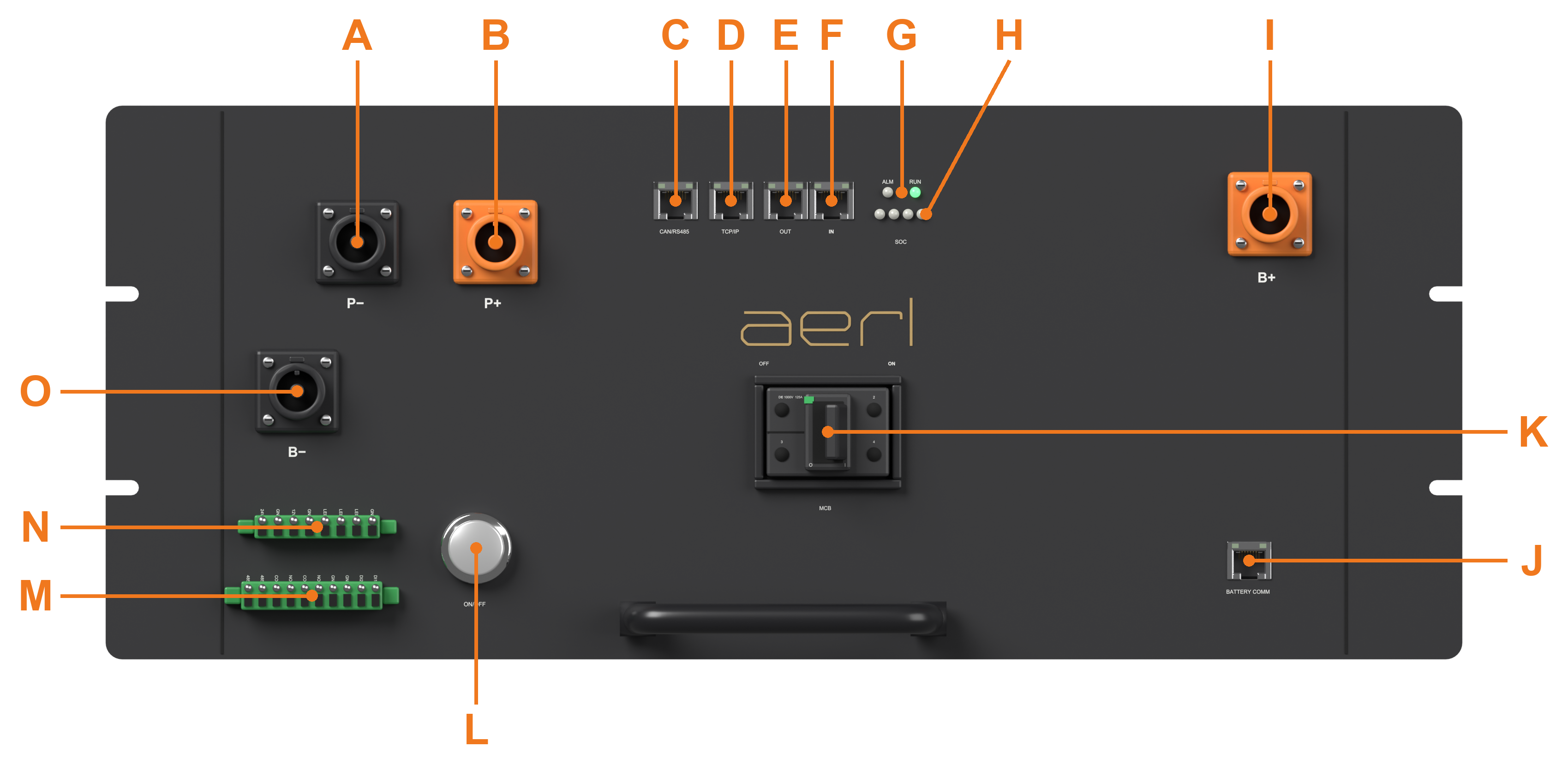
| Position | Label | Function |
|---|---|---|
| A | P− | System negative (to the inverter) |
| B | P+ | System positive (to the inverter) |
| C | CAN/RS485 | CAN or RS485 to the inverter or EMS |
| D | TCP/IP | Modbus TCP to the inverter or EMS |
| E | OUT | Parallel link out |
| F | IN | Parallel link in |
| G | ALM / RUN | Alarm and run LEDs |
| H | SOC | State-of-charge LEDs |
| I | B+ | Battery positive (from the last module in the string) |
| J | BATTERY COMM | Communication to the battery modules |
| K | MCB | DC circuit breaker |
| L | ON/OFF | Start / stop button |
| Position | Label | Function |
|---|---|---|
| M | Digital out / in (10-pin) | Air-conditioner RS485; 2 dry-contact outputs; emergency stop and fire-suppression inputs |
| N | Functional interface (8-pin) | 12 V / 24 V DC auxiliary output (10 W); run, alarm and lamp outputs |
| O | B− | Battery negative (from the module next to the PDU) |
Use Cat5e Ethernet cable for every IN, OUT, TCP/IP and CAN/RS485 connection.
| Pin | 1 | 2 | 3 | 4 | 5 | 6 | 7 | 8 |
|---|---|---|---|---|---|---|---|---|
| Signal | 11 V GND | 12 V | 11 V | CAN_H | CAN_L | 12 V GND | RS485 B | RS485 A |
Pins are numbered 1–8 from left to right, looking into the socket with the latch slot down.
Pins 1, 2, 3 and 6 carry 11–12 V DC. Do not use a straight-through cable to the inverter. Make up the inverter cable with only CAN_H and CAN_L (pins 4 and 5), or RS485 A and B (pins 7 and 8), wired to the inverter's pin order, and leave pins 1, 2, 3 and 6 unconnected unless AERL's setting guide for the inverter says otherwise.
The three LED groups on the PDU (ALM, RUN and SOC) show the system status.
| LED | State | Meaning |
|---|---|---|
| ALM | Red | Fault |
| ALM | Off | No fault |
| RUN | Green, steady | Running, communicating with the inverter |
| RUN | Green, slow flash | Running, no communication |
| RUN | Off | System off |
| SOC | 4 green | 75% < SOC ≤ 100% |
| SOC | 3 green | 50% < SOC ≤ 75% |
| SOC | 2 green | 25% < SOC ≤ 50% |
| SOC | 1 green | 0% < SOC ≤ 25% |
| SOC | First LED fast flash (0.5 s on, 0.5 s off) | SOC below 5% |
| SOC | Last lit LED flashes (1 s on, 1 s off) | Discharging |
| SOC | Last lit LED slow flash (2 s on, 2 s off) | Charging |
| Parameter | Tanami-M8.06 |
|---|---|
| Nominal energy | 8.06 kWh (8064 Wh) |
| Capacity | 105 Ah |
| Nominal voltage | 76.8 V DC |
| Operating voltage range | 60–87.6 V DC |
| Max. continuous current | 105 A (1C) |
| Peak current | 150 A (5 s) |
| Chemistry | LiFePO4 (LFP), prismatic cells |
| Dimensions (W × H × D) | 490 × 135 × 786 mm |
| Weight | 65 kg |
| IP rating | IP20 |
| Operating temperature | Charge: −10 to 55 °C / Discharge: −20 to 55 °C |
| Round-trip efficiency | ≥ 95% |
| Country of manufacture | People's Republic of China |
| Parameter | Tanami-PDU |
|---|---|
| Operating voltage | 200–1000 V DC |
| Max. current | 150 A |
| Communications | CAN / RS485 / Modbus RTU / Modbus TCP |
| Parallel systems | Up to 16 |
| Dry contacts | 2 outputs, 2 inputs |
| Auxiliary output | 12 V / 24 V DC, 10 W |
| Dimensions (W × H × D) | 490 × 200 × 545 mm |
| Weight | 15 kg |
| Modules | 6 | 7 | 8 | 9 |
|---|---|---|---|---|
| Nominal energy (kWh) | 48.38 | 56.45 | 64.51 | 72.58 |
| Nominal voltage (V) | 460.8 | 537.6 | 614.4 | 691.2 |
| Operating voltage (V) | 360–526 | 420–613 | 480–701 | 540–788 |
| Enclosure | RACK9 | RACK9 | RACK9 | RACK9 or CAB9-OUTD |
| Weight with modules (kg) | 495 | 560 | 625 | 690 (rack), 1050 (cabinet) |
All systems: max. continuous current 105 A, peak 150 A (5 s), round-trip efficiency ≥ 95%. Check that the system's operating voltage range lies within the inverter's battery voltage range before choosing the module count.
Compatible inverters: Solinteg, Solis and Deye high-voltage hybrid and battery inverters. Contact AERL to confirm the model and for its battery settings.
Prospective short-circuit current (for the AS/NZS 5139 arc-flash calculation): contact AERL.
| Parameter | Tanami-RACK9 | Tanami-CAB9-OUTD |
|---|---|---|
| Modules | 6–9 | 9 |
| Installation | Indoor | Outdoor |
| Dimensions (W × H × D) | 564 × 1773 × 783 mm | 780 × 1980 × 1300 mm |
| IP rating | IP20 | IP55 |
| Cooling | Natural convection | Air-conditioning (HVAC) |
| Auxiliary supply | None | 230 V AC, 50 Hz |
| Fire suppression | None (site system) | Aerosol unit |
| Fixing | Adjustable feet; anchored to the floor | 4 × M6 × 80 expansion bolts |
| Altitude | ≤ 3000 m | ≤ 3000 m |
| Humidity | Up to 95% (non-condensing) | Up to 95% (non-condensing) |
Certifications (system): IEC 62619, UN 38.3, CE, VDE-AR-E 2510-50, IEC 62040-1; outdoor cabinet also EN ISO 13849-1.
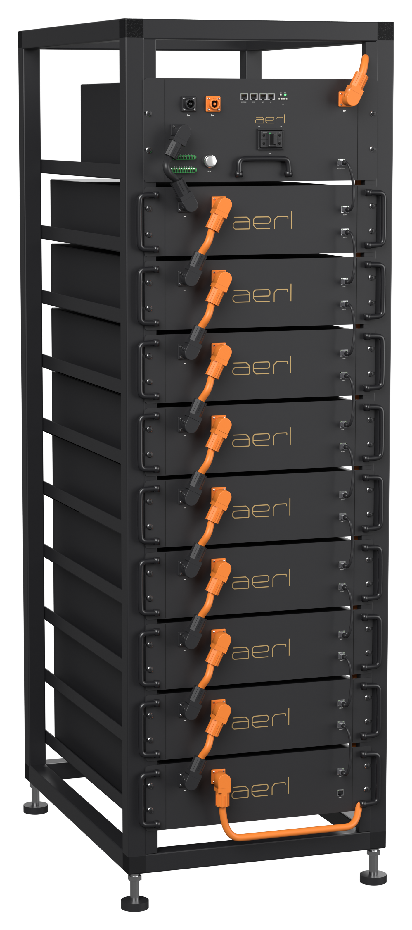
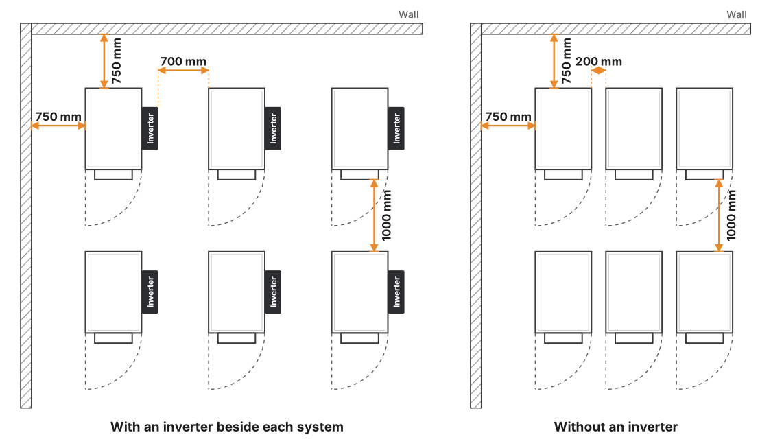
Install the Tanami system in accordance with this manual, AS/NZS 3000, AS/NZS 5139 and the inverter manufacturer's instructions.
Keep at least these clearances around each enclosure:
Fix the outdoor cabinet to the plinth through its four fixing holes with M6 × 80 expansion bolts. Level the indoor rack on its adjustable feet, then anchor it to the floor through its base with fixings suited to the floor, so it cannot tip.
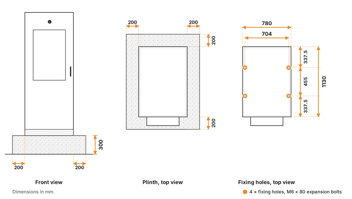
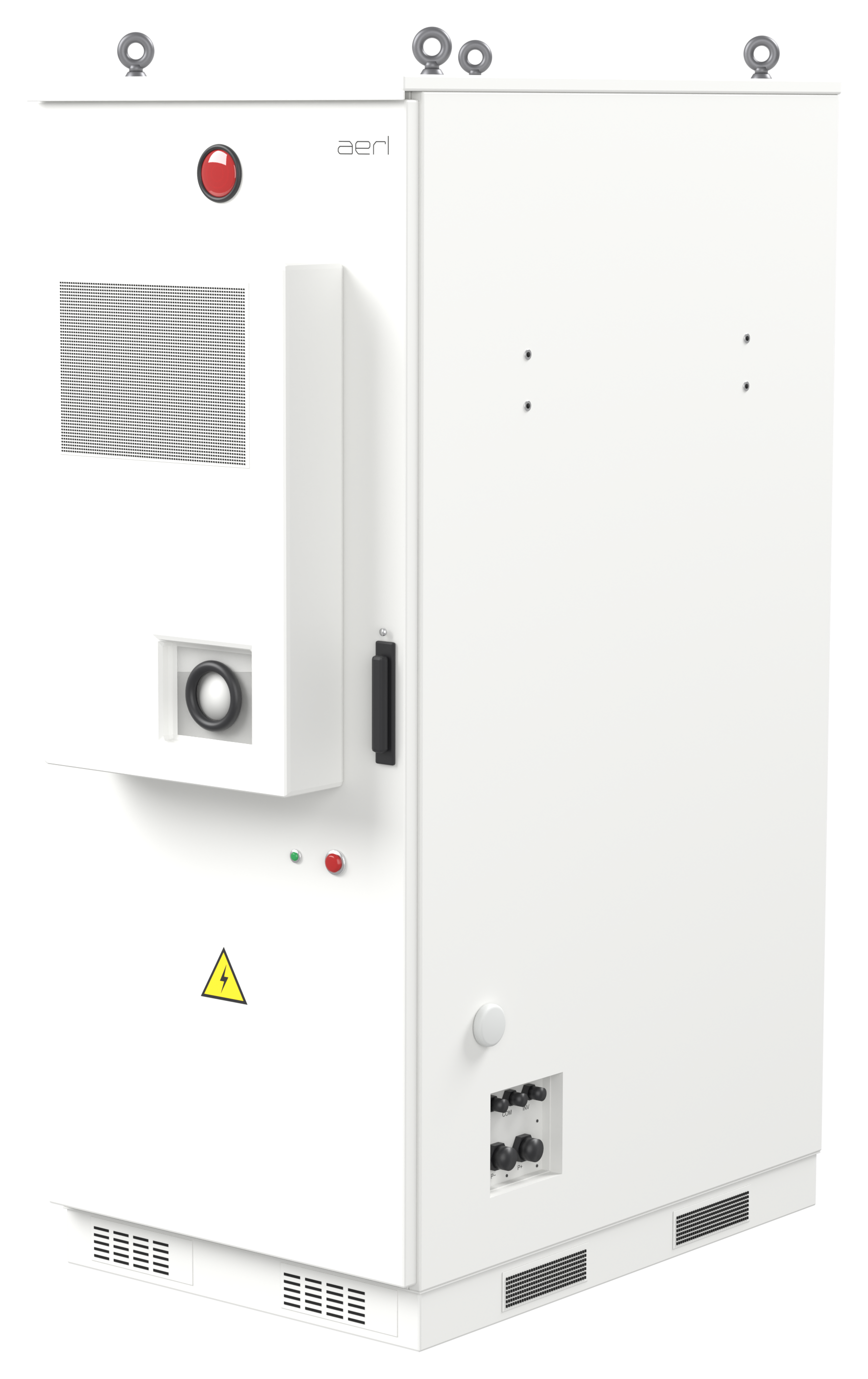
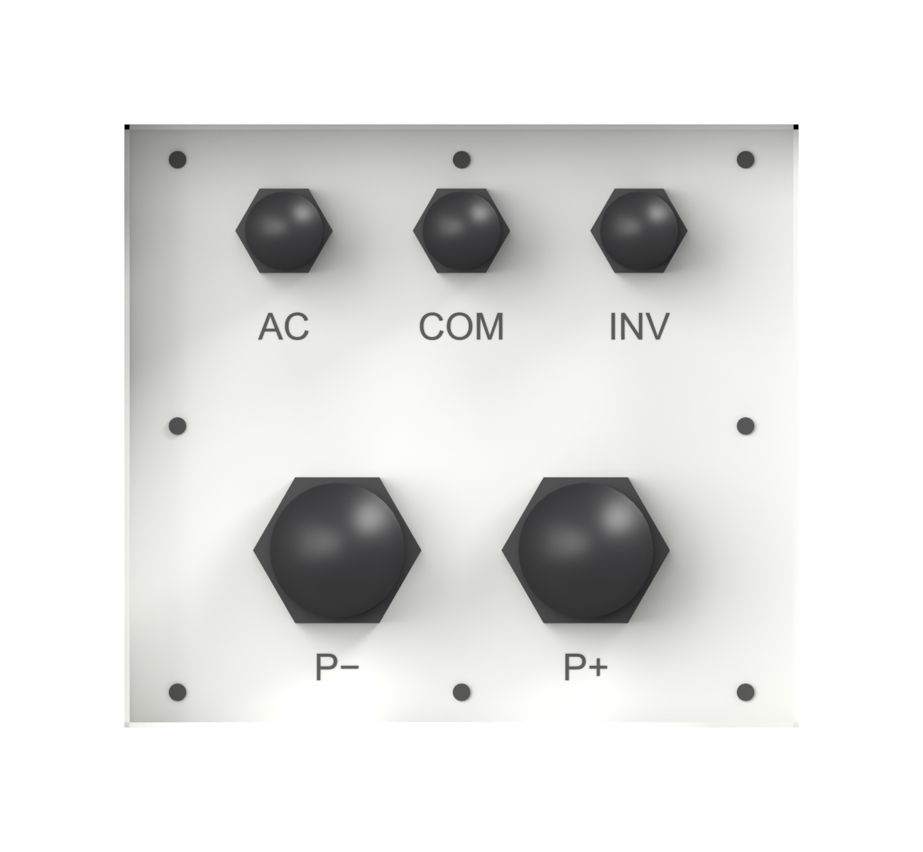
The outdoor cabinet has glands on both sides, near the base:
Both sides also have an overpressure relief valve and forklift pockets (230 mm apart, 700 mm across). The inverter can be mounted on the bracket on the right side of the cabinet.
Make sure the PDU breaker (MCB) is OFF before you connect any cable. The modules have no switch: each module's terminals carry 76.8 V DC nominal, and the series string reaches the full system voltage (up to 788 V DC) as you connect it.
Connect the enclosure's PE point to the site earth with a conductor sized to AS/NZS 3000 and AS/NZS 5139, before you connect any DC cable. In the outdoor cabinet the PE point is inside, at the bottom of the door opening.
Connect battery cable B from the negative (−) connector of the module next to the PDU to B− on the PDU: the bottom module in the outdoor cabinet (PDU at the bottom), or the top module in the indoor rack (PDU at the top).

Always plug the black connector into a negative (−) socket and the orange connector into a positive (+) socket.
Before connecting cable C, measure the string voltage with a multimeter rated for 1000 V DC, between the free positive (+) connector of the last module and the negative (−) connector of the module next to the PDU. Expect 60–87.6 V per module (about 77–80 V per module as delivered).
Set up the inverter's battery settings for the Tanami HV and the number of modules. Contact AERL for the settings for your inverter.
The outdoor cabinet needs a 230 V, 50 Hz AC supply for its air-conditioner and controls.
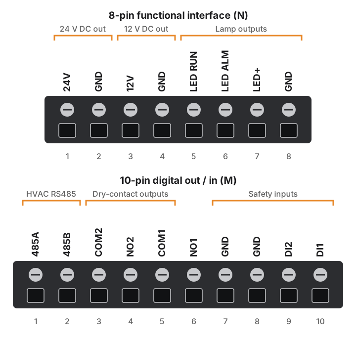
The PDU has two plug-in terminal blocks: the 8-pin functional interface (N in section 4.4) and the 10-pin digital out / in block (M). In the outdoor cabinet they come pre-wired to the cabinet's indicator lamps, air-conditioner, emergency stop and fire suppression.
| Block | Terminal | Function |
|---|---|---|
| 8-pin | 24V, GND | 24 V DC auxiliary output |
| 8-pin | 12V, GND | 12 V DC auxiliary output |
| 8-pin | LED RUN | Run lamp (green wire) |
| 8-pin | LED ALM | Alarm lamp (red wire) |
| Block | Terminal | Function |
|---|---|---|
| 8-pin | LED+, GND | Lamp supply (brown wire) |
| 10-pin | 485A | HVAC RS485+ |
| 10-pin | 485B | HVAC RS485− |
| 10-pin | COM2, NO2 / COM1, NO1 | Dry-contact outputs 2 and 1 (normally open): alarm and run signals for external equipment, such as a site alarm or generator start |
| 10-pin | DI1, GND | Emergency stop input (GND is the 8th terminal from the left) |
| 10-pin | DI2, GND | Fire suppression (aerosol) input (GND is the 7th terminal from the left) |
Up to 16 Tanami systems can run in parallel on one inverter DC bus. All systems in parallel must have the same number of modules.
The PDU that the inverter is connected to acts as the master, and the BMS addresses the other PDUs in the chain automatically when the systems start. Start the other systems first and the master last (section 6.2).
Before closing the DC isolators between systems, check that their voltages are within 10 V of each other (charge or discharge a system first if they are not), to limit the current that flows between them. Use DC cables of the same size and length from each system to the common bus, so that the systems share current evenly.
Before starting the system, check that:
The RUN and SOC LEDs light when the system has started. Then close the DC isolators and start the inverter as its manufacturer instructs.
In a parallel system, start each system in turn with steps 1–3, the master (the PDU the inverter is connected to) last, then close the DC isolators.
The Tanami can black-start an off-grid inverter: it energises the DC bus from the battery so the inverter can start without a grid or generator.
After black start is activated, P+ and P− carry the full system voltage (up to 788 V DC). Take extreme care.
The Tanami is monitored through AERL Cloud. An AERL Nexus Gateway on the site network reads the PDU over Modbus TCP and sends the battery's data to AERL Cloud, where the owner and installer can see the state of charge, voltages, currents, temperatures and alarms, and AERL can update the battery firmware remotely.
The battery modules need no routine maintenance. Check the system at least every 6 months:
Do not unplug any cable while the system is running. Shut the system down (section 6.3) before any work inside the enclosure. The module string stays live after shut-down (section 3.1).
Modules can be added to a system, or systems added in parallel, at any time during the product's life. All modules must be Tanami-M8.06, and every module count must stay within the enclosure's range and the inverter's voltage range:
Shut the system down (section 6.3) before adding modules. When it restarts, the BMS detects and addresses the new modules automatically. Then update the inverter's battery settings for the new module count.
When a Tanami battery reaches the end of its life:
The Tanami HV is covered by AERL's warranty: 10 years for the battery modules (70% state of health) and the PDU, 2 years for the indoor rack and the outdoor cabinet, and 1 year for the cabinet's aerosol fire-suppression unit. Conditions apply: see the Tanami HV Warranty Statement, at aerl.com.au. Register the system at aerl.com.au/warranty-registration.
If you have any questions or need support, contact AERL.
Sincerely,
The AERL Team
AERL Pty Ltd · 1/75 Bluestone Circuit, Seventeen Mile Rocks QLD 4073 · 1800 950 865 · [email protected] · aerl.com.au
Australian Energy Research Laboratories
1/75 Bluestone Circuit
Seventeen Mile Rocks QLD 4073
Australia